| Pages:
1
2
3
4
5
6
..
11 |
Cyrus
Hazard to Others

Posts: 397
Registered: 24-4-2004
Location: Ancient Persia
Member Is Offline
Mood: No Mood
|
|
And it would probably help if I actually posted the attachment

|
|
|
12AX7
Post Harlot
Posts: 4803
Registered: 8-3-2005
Location: oscillating
Member Is Offline
Mood: informative
|
|
Hmm...
Nothing wrong with horizontal plates, worth a try I suppose.  Vertical makes
more sense from the point of gasses getting away. You also get easier access to the faces of it, rather than burning one side unevenly. Vertical makes
more sense from the point of gasses getting away. You also get easier access to the faces of it, rather than burning one side unevenly.
Glasses are rarely conductive, but you make a good point, Fe3O4 might be possible. Matter of fact, you need to make one (you *do* need to make
one...*Jedi wave of hand*). I'd say, 80% Fe3O4 substrate, 20% clay. Might need as much as cone 10, I'll need to see if I can find an
FeO-SiO2-Al2O3 phase diagram to see where it melts.
Alternately, graphite fill. Try it!
To prevent leeching, you need a dense ceramic with few pores. You can fire dangerously close to the melting point, you can use a very fine particle
size (brute force method: smaller the clay, smaller the pores; pure ball clay is almost shiny after cone 10), you can add melters (borax, lime, soda)
to an otherwise refractory body (clay, alumina, silica, graphite) or you can add a protective glaze. I suggest a low-melt glaze applied thinly to the
surface so it mostly gets absorbed. You don't want something thick that'll interfere with the conductivity.
Tim
|
|
|
Cyrus
Hazard to Others
Posts: 397
Registered: 24-4-2004
Location: Ancient Persia
Member Is Offline
Mood: No Mood
|
|
| Quote: | Originally posted by 12AX7
Vertical makes more sense from the point of gasses getting away. You also get easier access to the faces of it, rather than burning one side
unevenly.
|
Well, I thought the idea was to prevent chlorine from escaping!  That's why "markx" (earlier in this thread) proposed horizontal plates. Oh, and to prevent burning one side of the anode, one could
only plate one side, which is just dumb, or put another (probably smaller) cathode below the anode...
That's why "markx" (earlier in this thread) proposed horizontal plates. Oh, and to prevent burning one side of the anode, one could
only plate one side, which is just dumb, or put another (probably smaller) cathode below the anode...
| Quote: |
Glasses are rarely conductive, but you make a good point, Fe3O4 might be possible... (silly content removed  ) ...'d say, 80% Fe3O4 substrate, 20% clay. Might need as much as cone 10, I'll need to see if I can find an
FeO-SiO2-Al2O3 phase diagram to see where it melts. ) ...'d say, 80% Fe3O4 substrate, 20% clay. Might need as much as cone 10, I'll need to see if I can find an
FeO-SiO2-Al2O3 phase diagram to see where it melts.
|
I have had only a little success with Fe3O4, but I may not have been firing it high enough.
Oh, and I will try graphite, but your jedi tricks can never make me try magnetite....I probably will though.
I think it will be almost impossible to make a ceramic substrate impervious to the solution, unless it's pretty much fused into a glass. (for
me at least) Ball clay has pores, right? After sitting for days and days in the chlorate cell, there has to be some solution adsorbed... Also, the
instructions I've seen call for a rough porous substrate so that the PbO2 coat will adhere well! But you could try using ball clay. (after all,
you have some, and I don't. You will try ball clay.)
And about the glaze... anyone know anything about conductive tin oxide containing glass? (I saw a post on it somewhere here.)
|
|
|
The_Davster
A pnictogen
Posts: 2861
Registered: 18-11-2003
Member Is Offline
Mood: .
|
|
I have been looking around at platinum wire for use as electrodes in a chlorate cell. The electrode will consist of the platinum wire(aprox. 50cm)
coiled around a glass tube. My question, is what is the minimum diameter of wire that I should use for this? Large diameter platinum wire is quite
expensive unfortunatly . .
|
|
|
axehandle
Free Radical
Posts: 1065
Registered: 30-12-2003
Location: Sweden
Member Is Offline
Mood: horny
|
|
| Quote: |
My question, is what is the minimum diameter of wire that I should use for this? Large diameter platinum wire is quite expensive unfortunatly.
|
Mine was 0.8mm and was very flimsy once hammered flat. It had to be handled with great care to avoid bending it accidentally. But since you're
goping to wind it around a dowel, thinner is probably OK. 0.5mm?
[Edited on 2005-6-8 by axehandle]
My PGP key, Fingerprint 5D96 E09E 365D 1867 2DF5 C2FE 4269 9C19 E079 CD35
\"Verbing nouns weirds the language!\"
|
|
|
The_Davster
A pnictogen
Posts: 2861
Registered: 18-11-2003
Member Is Offline
Mood: .
|
|
With yours hammered flat, did you ever encounter that slight erosion of the platinum would occur and corrode right through and break the electrode at
that place? I figure that I will need around 50cm of platinum wire for the electrode based on a mock-up I did with copper wire. Damn platinum is
expensive , anyone know any good(cheap) suppliers? I have googled my ass off
searching and even made use of google adds. , anyone know any good(cheap) suppliers? I have googled my ass off
searching and even made use of google adds.
Below is the electrode I hope to make, I am loosly basing my chlorate cell on the cell design from the site I took this picture from.
http://www.vk2zay.net/article.php/76
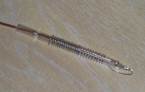
EDIT: Damn, can't get image tags working properly.
[Edited on 8-6-2005 by rogue chemist]
[Edited on 8-6-2005 by rogue chemist]
|
|
|
neutrino
International Hazard
Posts: 1583
Registered: 20-8-2004
Location: USA
Member Is Offline
Mood: oscillating
|
|
You can get the wire for a little over spot price on ebay. If you have an anvil, you may want to get a platinum band from a jeweler and hammer away.
|
|
|
axehandle
Free Radical
Posts: 1065
Registered: 30-12-2003
Location: Sweden
Member Is Offline
Mood: horny
|
|
| Quote: |
With yours hammered flat, did you ever encounter that slight erosion of the platinum would occur and corrode right through and break the electrode at
that place?
|
No, but I only ran the cell for 10 days or so. Isn't the corrosion of Pt supposed to be insignificant until the halt of XCl gets below 10%, BTW?
I think I've read that at several places. Then, as long as the chloride halt is kept healthily high and constant by adding KCl+water
periodically, the Pt should probably survive for a very long time.
Many "think", "probably" and "should" in that sentence, I know...
My PGP key, Fingerprint 5D96 E09E 365D 1867 2DF5 C2FE 4269 9C19 E079 CD35
\"Verbing nouns weirds the language!\"
|
|
|
Cyrus
Hazard to Others
Posts: 397
Registered: 24-4-2004
Location: Ancient Persia
Member Is Offline
Mood: No Mood
|
|
Well I made some clay substrates for anodes (not fired yet). They were made in a very nice, clean, and simple way.
Put a piece of fine cloth on the counter, then place two thin (3-4 mm thick?) parallel wood slats about 20 cm apart on top of the cloth, stick a hunk
of clay (coleman raku clay was used because it's very easily fired, plenty strong, and nicely porous) in the middle of the cloth between the
slats. Place another layer of cloth on top, and then use a rolling pin (y'all know what a rolling pin is, right? )
to flatten the clay perfectly. "Peel" off the top layer of cloth, then measure out how big the anode will be, and cut it out with a knife,
pizza cutter, etc. Let them dry for a few hours, then take off the bottom layer of fine cloth. This method worked perfectly, and I made 4 clay pieces
4 cm x 15 cm, 2 clay pieces (for testing purposes) 3 cm x ~2 cm, and one clay piece 6 cm x 20 cm. These are nice sizes for anodes, right?
The cell I'm hoping to use will have the following specs. (everthing depends on the transformer, which may not be properly tuned, so these may
not be exact)
About 4.1 L of solution will be used. (I'll make it at least 5L)
368 W ( 82A @ 4.5 V)
234 cm^2 of anode for current density of 350 mA per cm^2, which is supposedly the best. (I've got plenty of extra anode area so I can
lower/raise them)
I don't know the proper current density etc of the cathode. Any ideas? I would use plain steel except for the corrosion, perhaps graphite rods
would be better.
(I'm getting some diodes for the power supply. They are expensive. (Actually
the radio shack diodes were cheaper than the real electronics store diodes)
Cyrus
|
|
|
Cyrus
Hazard to Others
Posts: 397
Registered: 24-4-2004
Location: Ancient Persia
Member Is Offline
Mood: No Mood
|
|
Sorry for the double post, but I have an attachment.
Here's a simple schematic of my power supply. (see attachment)
You'll notice that there's not really any current limiting device besides a fuse. Is this reasonably safe? My concern is that the
resistance of the cell could be low enough that components overheat if the electrodes are too close together, etc. But according to Wouter and other
sites, there's not really any easy way to measure the current. (I could borrow a good multimeter, but they seem to think I'd need a rms
meter) I'd like to have some (cheap of course) way to "dial in" the current so that when testing new configurations, I could slowly
increase the current and check to make sure I wasn't giving it too many amps. I haven't bought the diodes yet, and I'm not certain how
large they should be. I'm thinking 60-120 A. (I'd use a few smaller diodes in parallel instead of two huge diodes, with a resistor in
front of each. )
Also, I'm not certain if I'll need to vary the voltage. I figure that if I set it at, say, 4.5 volts, it should work fine for chlorates and
perchlorates, but then again, apparently MOTs have poor voltage regulation. Any ideas? I suppose a few extra taps in the transformer secondary here
and there would be a good idea. Might be kind of hard when the secondary only has 4 turns.
Edit- Any ideas on what I should ground? The book I read indicated that the negative terminal was grounded in a typical full-wave rectifier.
[Edited on 9-6-2005 by Cyrus]

|
|
|
The_Davster
A pnictogen
Posts: 2861
Registered: 18-11-2003
Member Is Offline
Mood: .
|
|
Any problems with a Pt 92% W 8% alloy? I know a platinum irridium alloy is fine, but I am not sure about a platinum tungsten alloys usefullness in
such a cell.
|
|
|
12AX7
Post Harlot
Posts: 4803
Registered: 8-3-2005
Location: oscillating
Member Is Offline
Mood: informative
|
|
Cyrus: bum some dead computer switching power supplies and rip the schottky power diodes. Usually something like 40A 30V. A few in parallel will
hold up nicely.
R.C.: I can't find a Pt-W phase diagram in my collection, but I would assume it's either two phases or a solid solution (probably the latter
at only 8%). In that case, it ought to have the combined properties of Pt+W. If it is two phase, you'll have either grains of Pt inside a W
matrix (unlikely as W has the higher melting point) or W grains in a much wider Pt matrix. The latter would be preferred, I imagine, as W corrosion
won't undermine the Pt structure.
Tim
|
|
|
Cyrus
Hazard to Others
Posts: 397
Registered: 24-4-2004
Location: Ancient Persia
Member Is Offline
Mood: No Mood
|
|
| Quote: | Originally posted by rogue chemist
Any problems with a Pt 92% W 8% alloy? |
Well, the cost. I'd always have to worry about doing something wrong which would ruin the Pt, like getting the chloride conc. below 10%. (I
sometimes make mistakes, you know)
So far I've spent about $5 on lead dioxide making, and $4 on the power supply.
Tim, the diodes from a computer power supply sound nice, but I'm not sure where I'd get them, second hand stores perhaps.
Oh, and wouldn't a variable resistor (varistor?) work to control the amperage, like a lamp dimmer?
Wouter mentioned using variacs to tune the voltage IIRC...
|
|
|
12AX7
Post Harlot
Posts: 4803
Registered: 8-3-2005
Location: oscillating
Member Is Offline
Mood: informative
|
|
| Quote: | Originally posted by Cyrus
Tim, the diodes from a computer power supply sound nice, but I'm not sure where I'd get them, second hand stores perhaps.
|
You must not be a dumpster diver!!!
| Quote: |
Oh, and wouldn't a variable resistor (varistor?) work to control the amperage, like a lamp dimmer? |
Uh, I guess. You could also connect a variable inductor in series with the primary. Speaking of which, you should add some primary turns anyway, or
a buck transformer - I betcha that MOT runs warm with no load.
| Quote: | | Wouter mentioned using variacs to tune the voltage IIRC... |
Variable autotransformers work wonderfully if you have them!
Tim
|
|
|
evilgecko
Harmless
Posts: 36
Registered: 2-1-2005
Member Is Offline
Mood: Decomposing
|
|
I would not recommend using varible resistors to control the current needed for a chlorate cell. Pots with 2A+ ratings are very rare and expensive and
are extremely good at converting chemical energy into heat!
IIRC light dimmers work by varing the frequency of the AC voltage to control the output power. This is also unsuitable for a DC powered cell.
I think the best way to go would to use the distance (or is it length ) between
the electrodes to control current. This means you would have to have movable electrodes which can be a pain in the brain.
Another way is to use a variac, which is what axehandle used for his furnace. Good quality ones are quite expensive though and might empty the pigs
belly.
So many decisions so little time...
|
|
|
tumadre
Hazard to Others
Posts: 171
Registered: 10-5-2005
Member Is Offline
Mood: No Mood
|
|
your power supply is only as good as the amount of current it can deliver, use a computer power supply, they are the most effective at five volts. It
makes no difference whether you increase the distance between the elements in the cell or use resistors in the power supply.
|
|
|
Cyrus
Hazard to Others
Posts: 397
Registered: 24-4-2004
Location: Ancient Persia
Member Is Offline
Mood: No Mood
|
|
| Quote: | Originally posted by evilgecko
I would not recommend using varible resistors to control the current needed for a chlorate cell. Pots with 2A+ ratings are very rare and expensive and
are extremely good at converting chemical energy into heat!
IIRC light dimmers work by varing the frequency of the AC voltage to control the output power. This is also unsuitable for a DC powered cell.
|
Oops. I didn't mean a potentiometer, but a rheostat. (bigger) It would be put in series with the primary, of course.
If light dimmers work by varying the frequency of the AC voltage, they could be put in series with the primary winding of the transformer, which is
still AC.
Tumadre, I'm not sure what your point is. I'm trying to have a setup where I can increase the amperage (or voltage) gradually from zero up
to the desired amount.
Moving the anodes/cathodes around might just be the simplest solution...
[Edited on 10-6-2005 by Cyrus]
|
|
|
Cyrus
Hazard to Others
Posts: 397
Registered: 24-4-2004
Location: Ancient Persia
Member Is Offline
Mood: No Mood
|
|
Well, I decided to use a nice large glass jar (3.5 L capacity if I fill it to within an inch or so of the brim. That is probably too close to the
top...)
That means I'll only need about 60 - 70 amps. It also means that the
anodes/cathodes will not be very adjustable, because they have to fit inside of a reasonably narrow bottle neck.
According to Wouter Visser, in a chlorate cell graphite anodes run at 30 mA per square cm, while (perhaps it was that geocities place http://www.geocities.com/CapeCanaveral/Campus/5361/chlorate/... ) in a perchlorate cell they run at 200-350 mA per square cm! To those who have
made (per)chlorate- what current densities on the anodes and cathodes do you use, and how well did they work? (PbO2 anodes in particular)
Also, which grades of stainless steel are suitable with PbO2? (Chromates can't form as they will ruin the efficiency.)
Edit-
~Grades of SS that are ok are type 347 and food grade is not too bad.
Other alloyes that are good are Durimet 20, Hastelloy HB-1, Hastelloy HC-3, Hastelloy C.
~
(taken from the web address mentioned earlier in this post)
Edit 2- I got a nice looking fluorescent lamp dimmer for $5. Apparently they do work by chopping up the sine wave of the 117 v input. Poor sine
wave. Anyways, will this work with the power supply I am envisioning? I suppose the DC output will just be really jagged. (unless I install a large
capacitor)
BTW, how the heck am I going to measure how many amps flow through this thing? Some of the multimeters I've seen only go to 250 mA. I could
"borrow" a capacitor from a large motor I have, put it across the output to smooth things out, measure the voltages at the output,
calibrate the light dimmer using those numbers, and then find the resistance across the cell. Which would depend on temperature, the phase of the
moon, etc....
[Edited on 14-6-2005 by Cyrus]
|
|
|
Magius
Harmless
Posts: 20
Registered: 9-6-2004
Location: Green Bay
Member Is Offline
Mood: Constrianed
|
|
Dang Cyrus, sounds like you cell is gonna be awesome. Wish I had the time/patience/chems to make a Lead Dioxide Anode, but my graphite stands up fine
after being soaked in linseed oil for 4-5 days.
Since you have a PbO2 anode, and chromates in the cell will screw up your efficiancy, why don't you try getting some Titanium wire? I got 20ft of
.883mm wire off ebay for 12$, and I can say for certain that more chloride is absorbed in the cell becuase i was able to spiral the Ti wire around the
anode.
On your questions for current density, my averages 300mAmps/cm^2 or so, and the errosion doesn't seem that bad, althought the crystal's that
have been forming do get alittle black from erroded graphite. Not sure how your PbO2 anode will hold up, probably much better than a graphite welding
rod.
As for the crystal's forming, this is where I've been having some problems. My cell is currently running on KCl, but I think that I may have
to switch to NaCl becuase of the crystal creep problems I've been having. Some KClO3 crystalizes out on the bottom of the cell, but a mix of
KClO3 and KCl forms as crystal where the anode and Cathode enters into the cell, and when the water is lost, I end up with a large hunk of crystal
wedged between my anode and cathode. Just thought I'd like to warn you, (and see if anyone knows a solution) keep the solution level in your cell
at least 2 inches below where the anode and cathode enters the Cell, otherwise the crystal will creep out of the Cell and all over the place. Not fun
to clean up.
Good Luck
Wait for it...
|
|
|
12AX7
Post Harlot
Posts: 4803
Registered: 8-3-2005
Location: oscillating
Member Is Offline
Mood: informative
|
|
Something I've been thinking about, what if you have a long tank. Heat from the electrolysis would set up convection from one end to the other.
Hang a basket of coarse salt around the electrodes (to maintain a concentrated chloride solution) and periodically rake the chlorate out of the cool
end. Theory being the cyclic heating and cooling of the solution causes soluble salt to dissolve and displace less soluble (and in particular, much
less soluble when *cooled*) chlorate, pushing the equilibrium in one direction.
Tim
|
|
|
12AX7
Post Harlot
Posts: 4803
Registered: 8-3-2005
Location: oscillating
Member Is Offline
Mood: informative
|
|
BUMP!
I'm starting the season early for a change. My power supply is low on voltage so I'll run it for a few weeks at a time until mid-June arrives. 
I happen to have this big chunk of stainless steel tubing, so I welded a plate to the bottom (welding must be like riding a bike, I only got one
pinhole after the first try :cool I've still got two 1.5" square 18" bars of
graphite (hmm, I do recall they're 18"...that must mean the cell is actually more like 16", not 20), so I'm just going to be lazy and drop one inside.
I cut a bunch of 3/8" long chunks of PVC pipe to cover the bottom so the anode doesn't rest on a short circuit.
Tim

|
|
|
12AX7
Post Harlot
Posts: 4803
Registered: 8-3-2005
Location: oscillating
Member Is Offline
Mood: informative
|
|
Real picture:

Garbage bag stuffed in the annulus to reduce fumes. Works pretty well! The spring loaded clamp holds a copper strap to the top of the bar, which
doesn't corrode too badly considering. The power supply, out of view, is a microwave oven transformer I rewound for low voltage and added some diodes
and capacitors to get DC.
And yes, I had just changed out the electrolyte. Gets kinda dirty as you can see. Filters cleanly through packed glass wool.
The propane torch just beside was just being used, incidentially, to cook down the hypochlorite from that run. Having a steel cell is very nice...
Last night I was also recrystallizing some KClO3 I didn't even realize I had. Turns out the last batch was significantly more yield than I had
thought -- efficiency WAS good, after all. Here are some unusually large crystals.

Tim
|
|
|
dann2
International Hazard
Posts: 1523
Registered: 31-1-2007
Member Is Offline
Mood: No Mood
|
|
| Quote: | Originally posted by MadHatter
Snipppp
Mark, that's 10 watts if your voltage and current numbers are correct. I use a battery
heated to boiling, To this boiling mixture, 5ml of the cell solution are added. Five parts per million of Chlorate will cause a sharp decoloration of
the indicator, and one part per million can be detected.
I use this test when making perchlorates. Attached is 3 pictures of a test I did less
than 1 hour ago. I dissolved .01 grams of KClO3 in 10 ml water as the solution to
"test". In the 3 pictures from left to right.
Picture 1 shows my 250 ml reagent bottle of indigo carmine indicator. This was made by dissolving .25 grams of indigo carmine in 250
ml distilled water. It's a dark blue liquid.
Picture 2 shows a 50 ml beaker. In it contains 5 ml indigo carmine indicator and 25 ml
31% HCl(purchased at Ace Hardware). The 5-to-1 ratio of HCl to indicator is maintained.
Picture 3 shows what happened after boiling the beaker and adding 3 DROPS of the "test"
solution. |
Greeting Mad Hatter,
The Chlorate/Perchlorate threads will just never stop....
Would it be OK if I put the pic (of the Inidgo Carmine) on my web site.
Cheers,
Dann2
|
|
|
12AX7
Post Harlot
Posts: 4803
Registered: 8-3-2005
Location: oscillating
Member Is Offline
Mood: informative
|
|
BUMP!
An FYI for the thread:
I have an ammeter of debatable accuracy. Looks like it was for a battery charger or so. The best I ever got with the above setup was 30A, and that's
hot (while boiling the solution). Under normal conditions I got about 20A. (This is to about one significant digit, no, not a very useful meter /
only "just" useful.)
The other day, I accidentially shorted the power supply, enduring a current in the 60-80A range, which eventually blew a rectifier somewhere (although
I didn't find a failed junction when ohming them out later). So, I took it upon myself to use my larger MOT core, which I'm not using for line
isolation anymore, and put some heavy wire on it. I also took the liberty of making it a centertapped winding, so I can parallel my two remaining
dual diodes, giving some 60A capacity. I also decided to pick off the shelf a rather large inductor I made some years ago, intended for welder duty.
It has, I think 8 turns of #0 AWG aluminum wire on a gapped MOT core. It seems to help, reducing ripple to a few volts. The transformer and heatsink
run a bit hot (the transformer by design, unfortunately), so I added a reasonable fan (40 CFM?), which is keeping things nice and touchable.
At 60A load, I get 6VDC output, so I added a bit of steel wire ballast in series with the cell, bringing it down to 3.6VDC or so. The cell is now
running three times faster, and operating at 65°C (150°F). I should be gathering about three pounds of sodium chlorate per week!
Tim
|
|
|
dann2
International Hazard
Posts: 1523
Registered: 31-1-2007
Member Is Offline
Mood: No Mood
|
|
Hello,
What is the Anode?
Dann2
|
|
|
| Pages:
1
2
3
4
5
6
..
11 |


