| Pages:
1
2
3
4
5 |
woelen
Super Administrator

Posts: 7976
Registered: 20-8-2005
Location: Netherlands
Member Is Offline
Mood: interested
|
|
I made a completely new ZVS driver with IRFP260s, 5 W 470 Ohm ceramic resistors, 10 kOhm metalfilm resistors, 13 V zener diodes and hand wound choke
inductor on yellow/white powdered iron core. I used a flyback transformer (old Nokia thing), with a DC cascade at its output. The result with the new
ZVS driver is quite impressive. From a fixed 13.8 V power supply it starts sparking at 2 cm distance! The only strange thing is that I have many fat
and very noisy sparks per second from the cascade and not a smooth arc. I think I have 10 or so fat sparks. Probably, the cascade contains a capacitor
at its output, which is charged every 100 ms or so.
Anyway, this driver is much better than the previous one. It looks ugly though. The PCB I ordered was not made for the components I used (e.g. the
diodes, suggested by IrC have very thick wires, which cannot go through the drilled hole in the PCB, the resistors I have are intended for lying on a
PCB, while the PCB is designed for resistors which can stand on the PCB). So, I needed quite a lot of tinkering and improvising before I had a working
driver. So, mechanically it is of much less quality, but electrically it is superior.
Btw, I replaced the 470 nF capacitor by a 330 nF one. I don't have 630V 470 nF capacitors anymore, but I have plenty of 330 nF/2 kV and 1 uF/630 V. I
chose to take the 330 nF one. I have room left on the PCB to add another one in parallel to the one I already added.
I also noticed that the new circuit uses a remarkably low current. After I switch off my power supply it keeps on sparking for well over a second or
so, while the power supply only has a 47000 uF capacitor behind its rectifier. The previous version of the driver immediately stopped generating
sparks with the same flyback/cascade device when the power supply was switched off.
[Edited on 15-9-14 by woelen]
|
|
|
seilgu
Harmless
Posts: 13
Registered: 24-10-2014
Member Is Offline
Mood: No Mood
|
|
latchup
Has anybody found a way to improve the circuit so it doesn't latchup and blow mosfets?
I've built this circuit years ago and it worked fine, recently I brought it out and found that if the power supply doesn't rise fast enough, the
circuit latches up and one mosfet conducts heavily, while the other one remains shut off. I'm using a linear benchtop supply so current it limited to
3A and no mosfet were blown.
I'm not sure I understand this circuit correctly. When powered up, the voltage on both mosfets will rise to about 3V, and one of them (A) will start
to conduct more first. At this point the current from the power supply will flow both sides, because the capacitor is being charged on the B side. The
positive feedback will turn mosfet A fully on, thus shutting mosfet B fully off.
Suppose the B side now charges fully, and current stops flowing into the B side. If the center tap of the inductor is at voltage V, then since mosfet
A is at 0V, mosfet B would be at 2V. The current through A side will continue to increase following V = L*dI/dt, until either the supply limits or the
inductor saturates.
If the supply is limited, the inductor current will have to come from the B side, thus starting the cycle. However if it is due to saturated inductor,
it just means the L value becomes small, thus the supply will have to provide larger dI/dt. Therefore the need for a RFC choke on the supply.
Still can't see why latchup occurs.... 
|
|
|
Metacelsus
International Hazard
Posts: 2531
Registered: 26-12-2012
Location: Boston, MA
Member Is Offline
Mood: Double, double, toil and trouble
|
|
I've never had latchup problems on the circuit I built, although I have heard of others having them. They seem to be mitigated by proper gate resistor
adjustment. What values of resistors are you using on the MOSFET gates, and how big is your inductor?
|
|
|
seilgu
Harmless
Posts: 13
Registered: 24-10-2014
Member Is Offline
Mood: No Mood
|
|
latchup
I used a ferrite-core 47uH (marked as that, didn't test). Today I replaced it with higher inductance and the latchup problem is mitigated. If I use a
very large inductor it doesn't latchup (but of course it would reduce the power output).
resistor values are as the original, 470 and 10k.
What might be the reason behind this?
[Edited on 24-10-2014 by seilgu]
|
|
|
WGTR
National Hazard
Posts: 971
Registered: 29-9-2013
Location: Online
Member Is Offline
Mood: Outline
|
|
Quote: Originally posted by seilgu  | Has anybody found a way to improve the circuit so it doesn't latchup and blow mosfets?
I've built this circuit years ago and it worked fine, recently I brought it out and found that if the power supply doesn't rise fast enough, the
circuit latches up and one mosfet conducts heavily, while the other one remains shut off. I'm using a linear benchtop supply so current it limited to
3A and no mosfet were blown.
I'm not sure I understand this circuit correctly. When powered up, the voltage on both mosfets will rise to about 3V, and one of them (A) will start
to conduct more first. At this point the current from the power supply will flow both sides, because the capacitor is being charged on the B side. The
positive feedback will turn mosfet A fully on, thus shutting mosfet B fully off.
Suppose the B side now charges fully, and current stops flowing into the B side. If the center tap of the inductor is at voltage V, then since mosfet
A is at 0V, mosfet B would be at 2V. The current through A side will continue to increase following V = L*dI/dt, until either the supply limits or the
inductor saturates.
If the supply is limited, the inductor current will have to come from the B side, thus starting the cycle. However if it is due to saturated inductor,
it just means the L value becomes small, thus the supply will have to provide larger dI/dt. Therefore the need for a RFC choke on the supply.
Still can't see why latchup occurs....
|
I posted something earlier in the thread here:
https://www.sciencemadness.org/whisper/viewthread.php?tid=31...
Successful startup depends on there being a slight difference between the two MOSFETs, with a fast rise time in the power supply voltage. If this is
not possible, then noise injected into the gates may be necessary to get it started (hopefully before the device melts down).
What supply voltage are you using? 3V? If so, you need quite a bit more than that, depending on the gate threshold of your MOSFETs. It's possible
that one is turning on, while another isn't, due to part variations.
Personally, I prefer designs that consume no power when there is no gate drive. They are much safer.
|
|
|
seilgu
Harmless
Posts: 13
Registered: 24-10-2014
Member Is Offline
Mood: No Mood
|
|
latchup
There is always going to a slight difference between the MOSFETs, I heard somebody saying that for the noise to start the oscillation, the feedback
gain should be larger than 1.
I don't understand how it works tho. Assuming gate A has a noise of exp(-iwt), that would translate to the drain current in the same phase, the gain
determined by the V_GS to I_DD diagram in the datasheet of the MOSFET. Now assuming w is the LC tank frequency, that would mean the parallel LC tank
looks like a infinite resistance to the exp(-iwt) noise, therefore the gain at mosfet B should be infinite! Why doesn't this start the oscillation?
My supply voltage is slow rising because I manually turn up the regulated voltage. It's well above 3V of course, the supply has a max voltage of ~45V.
I'm looking for some improvements for this circuit, of course one way is to use a 555 timer and if one mosfet latchups too long it would reset the
circuit. Since I'm only using it for small powers I don't really need that actually...
|
|
|
Metacelsus
International Hazard
Posts: 2531
Registered: 26-12-2012
Location: Boston, MA
Member Is Offline
Mood: Double, double, toil and trouble
|
|
You could just put a switch between the supply and the circuit, and turn it on once you've set the voltage.
|
|
|
seilgu
Harmless
Posts: 13
Registered: 24-10-2014
Member Is Offline
Mood: No Mood
|
|
latchup
That is a solution, but not a robust one.
For example if the load is suddenly changed it might still go into latchup mode. Therefore a protection circuit or a guaranteed oscillating design is
still preferred. Also it could save lots of mosfets for newbies..
|
|
|
WGTR
National Hazard
Posts: 971
Registered: 29-9-2013
Location: Online
Member Is Offline
Mood: Outline
|
|
On slow power supply ramp up, if both MOSFETs conduct at the same time, the tank circuit is effectively shorted out. This means it has practically no
inductance, if the windings are well-coupled. (Temporary) current limiting now depends on the series choke, which will probably saturate more quickly
than you can ramp the supply voltage. At that point you have a big, saturated, steaming pile of silicon and ferrite (unless you have a
current-limited power supply, under which conditions it merely simmers with mild annoyance).
To make this work, the series choke needs to be able to handle without saturating whatever current the power supply can deliver. Also, the gate drive
to both MOSFETs needs to be kept at zero when the device is not oscillating. This latter point is the opposite of how a typical Mazilli driver
works, as it supplies gate drive to both devices on power up, and relies on one device out-competing the other to get oscillation going. If
oscillation doesn't start, well, then both devices smoke.
Think about this: given that both MOSFETs should be "OFF" when not oscillating, but with the functioning circuit remaining within the design
constraints of a Mazilli-type design, could you modify the design to work with, say, a temporary pushbutton that could get the oscillator started?
And a circuit that, if it stopped oscillating under load, would allow the gate drive to drift to zero?
|
|
|
seilgu
Harmless
Posts: 13
Registered: 24-10-2014
Member Is Offline
Mood: No Mood
|
|
| Quote: Originally posted by WGTR | On slow power supply ramp up, if both MOSFETs conduct at the same time, the tank circuit is effectively shorted out. This means it has practically no
inductance, if the windings are well-coupled. (Temporary) current limiting now depends on the series choke, which will probably saturate more quickly
than you can ramp the supply voltage. At that point you have a big, saturated, steaming pile of silicon and ferrite (unless you have a
current-limited power supply, under which conditions it merely simmers with mild annoyance).
To make this work, the series choke needs to be able to handle without saturating whatever current the power supply can deliver. Also, the gate drive
to both MOSFETs needs to be kept at zero when the device is not oscillating. This latter point is the opposite of how a typical Mazilli driver
works, as it supplies gate drive to both devices on power up, and relies on one device out-competing the other to get oscillation going. If
oscillation doesn't start, well, then both devices smoke.
Think about this: given that both MOSFETs should be "OFF" when not oscillating, but with the functioning circuit remaining within the design
constraints of a Mazilli-type design, could you modify the design to work with, say, a temporary pushbutton that could get the oscillator started?
And a circuit that, if it stopped oscillating under load, would allow the gate drive to drift to zero?
|
I don't think there is the remote possibility of both MOSFETs smoking. When one turns on it immediately turns the other off, they can't be on at the
same time.
They can't be both off, either. When not oscillating, one is on and the other is off, and it doesn't switch.
The way to get is restarted is for the feedbackloop to have a gain larger than 1 at the desired frequency so that any noise of the frequency will get
amplified.
The other way to prevent latchup is to detect latchup either by checking how long the MOSFETs turn on or how hot the thing gets. Although if used with
large power supplies, you'd be already too late when it feels hot.
|
|
|
WGTR
National Hazard
Posts: 971
Registered: 29-9-2013
Location: Online
Member Is Offline
Mood: Outline
|
|
| Quote: Originally posted by seilgu |
I don't think there is the remote possibility of both MOSFETs smoking. When one turns on it immediately turns the other off, they can't be on at the
same time.
They can't be both off, either. When not oscillating, one is on and the other is off, and it doesn't switch.
|
It depends a lot on the ratio of FET "ON" resistance to the tank coil DC resistance. If this ratio is high, then when not oscillating the voltage on
both drains will be about equal. If the circuit latches up with one driver off (like you mentioned), then the winding resistance of the tank coil is
relatively high (especially since the supply is limited to 3A).
If I understand your previous posts correctly, the power supply goes into current limiting at 3A, supplying 3V when the circuit is latched up. This
would imply that there are about 2 ohms DC resistance across the whole winding. Can you measure it?
| Quote: Originally posted by seilgu |
The way to get is restarted is for the feedbackloop to have a gain larger than 1 at the desired frequency so that any noise of the frequency will get
amplified.
The other way to prevent latchup is to detect latchup either by checking how long the MOSFETs turn on or how hot the thing gets. Although if used with
large power supplies, you'd be already too late when it feels hot.
|
Yes, loop gain greater than +1 is needed for oscillation at the frequency of interest, but when the drivers latch up, the FETs are no longer operating
in a linear range. At that point there is practically no small-signal amplification. Thermal noise won't be enough to get it going.
If you want to try getting this to work, I would suggest as a first step to decrease the tank winding resistance enough that both FETs turn on when
the circuit is not oscillating, and the drain voltages are approximately equal. Second, add two small inductors in series with either side of the
tank coil, with a small percentage of the overall reactance. Thirdly, make sure that none of the magnetics are saturating with your 3A supply.
I'm getting tired enough right now that I am beginning to hallucinate that chipmunks are telling me what to write. That must mean that I need to go
to bed.
|
|
|
violet sin
International Hazard
Posts: 1475
Registered: 2-9-2012
Location: Daydreaming of uraninite...
Member Is Offline
Mood: Good
|
|
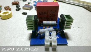
So I've been working on a zvs driver myself. Finally decided to put together parts that I bought a few years back not sure if they are all in the same
category of power consumption for the proper circuit. Parts are as follows: mosfet- IRFP250N, fast diode- UF4007, zen diode- 1N-5349B, 1uF MKP10 cap
1000-600~, 5w 470 ohm, 1/4w 10k ohm,

Ended up copying an online schematic and making my own PCB board. Got everything etched and soldered in place except for the inductor coil. For a non
electronics guy some of this stuff is kind of hard to pick up, like figuring out on the parameters to wind your own. I can usually gather enough info
just reading online, but lately life gives me my spare time in numerous shorter lengths. While working away I only get to use my cell phone for
internet Leads to learning simple things many times over, and little time for
theory.
Any suggestions for whether or not the yellow/white T106-26 core would be good? Pretty sure it was from a ATX PSU.
I do have T 106 26 white yellow iron powder core, a few ferrite cores unmarked and bare. I also have three spools of magnet wire from RadioShack the
thickest is 22 gauge but I do also have 26 and 30 gauge
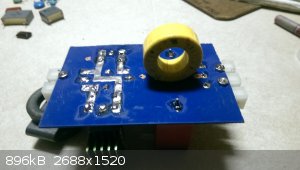
Also, etching.g was done pretty easily. One SOS pad, muriatic acid, little bit of rust and some hydrogen peroxide 3%. The solution was ready in about
half an hour, and etched rather rapidly. 10 minutes was almost too long as the traces we're getting undercut.
Any input on the inductor core would be great, so far the online calculators I am seeing say between 38 and 42 raps on the core with the 22 gauge wire
that I have( for about 150 uH). But the schematic that I had only states between 47 and 200 Micro Henrys of inductance, is a pretty wide open guess
for someone who doesn't have the know-how or eyes for mismatch problem.
I have a fly back to try it on, but will eventually be building an induction heater. I don't reall need big sparks for fun, But melting metal sounds
productive 
|
|
|
IrC
International Hazard
Posts: 2710
Registered: 7-3-2005
Location: Eureka
Member Is Offline
Mood: Discovering
|
|
100 uH might be fine but safer to go with 150 uH, or you risk the circuit not starting. This can result in the mosfets turned on steady, blowing them.
As to the gauge 22 is OK if you do not plan on more than 5 amps DC input. You need to determine what maximum wattage rating you wish to have and go
from there as to the chokes current handling ability. If you plan on metal melting you need to go for a kilowatt design at least so your choke would
need a better current rating. For example at 24 volts you need a choke able to handle over 42 amperes while being a minimum of 150 uH. I use 100 uH
often because I had a good quantity but I have turned it on and blown mosfets a few times. I do not know why they would have given a range as low as
47 uH, unless they also make a living selling parts. Keep in mind the choke must handle whatever total current you will see and if I had to pick a
minimum inductance it would be around 120 uH to guarantee starting every time power is applied. The yellow core shown should be fine for what you are
doing right now. You want a core large enough to take enough turns at the wire size you choose to reach the required inductance, and consider in high
power designs core saturation. I should also mention you can reduce the current requirement if you operate at higher voltages such as 48 volts instead
of 24. However you must consider shrapnel protection from exploding parts, the circuit starts to become really dangerous as you operate on higher
voltages. You mention 1 uF, I found better efficiency at 0.33 to 0.66 uF for the circuits I built operating under 1KW. Be sure to over rate the
voltage, this component likes to explode. I have had them sound like a shotgun blast leaving dents in shielding. Very dangerous especially in the 50
volt and higher power input range.
"Science is the belief in the ignorance of the experts" Richard Feynman
|
|
|
violet sin
International Hazard
Posts: 1475
Registered: 2-9-2012
Location: Daydreaming of uraninite...
Member Is Offline
Mood: Good
|
|
Thanks for the help there IrC, much appreciated. I cut wire to the specs of the coil calculator and came up a couple turns shy of the 150uH rating.
~135 as it was two turns under 150 and two turns over 120. By online calculator, my multimeter isn't that multiple in function soon enough.
It's all wound, soldered, the 5+5 on fly back done... Be home tomorrow to throw it on a power supply
Then on to the next planning stage, the induction heater. Side note, solder or flux seems to be eating my irons rather rapidly. Butane one I've had
for years and a new harbor freight one see damage immediately. Not a fan of that.
|
|
|
IrC
International Hazard
Posts: 2710
Registered: 7-3-2005
Location: Eureka
Member Is Offline
Mood: Discovering
|
|
Should be adequate inductance. As to soldering get used to it, welcome to the 21st century. Organic fluxes that smell like burning antifreeze
stripping metal off the tips, crappy non lead solder, tips made so cheap its infuriating. 40 years ago I could leave my 33 watt Ungar with Iron clad
tip (and I mean nice thick plating) running 24/7 for months never needing to change a tip. Or heater for that matter, even they are now so poor
quality they fail in very short times. In the past avoiding thermal cycling I could get a tip to last through several 1 lb rolls of 0.032 and 0.044
64/37 rosin core and have had heaters last a decade. In fact one I bought in 1984 burned out just last year. Same with the desoldering heads. Instead
of a year or two now I'm lucky if one lasts 3 months. Now I only have one on when using it since the heaters and tips I like best are getting harder
to find. Add to that solder that fails to flow nicely and quickly to avoid foil lifting on ever thinner traces (cheap bastards saving Cu costs), and
joints that crystallize easily. If I had known the future I would have bought enough supplies back in the 70's to last until I became too feeble to
work anymore. One other consideration: use a variable supply and start low around 10 or 12 volts. The efficiency of this design is so high you can
easily destroy your fly-back transformer if you are not careful. Better to work your way up to the maximum voltage.
"Science is the belief in the ignorance of the experts" Richard Feynman
|
|
|
violet sin
International Hazard
Posts: 1475
Registered: 2-9-2012
Location: Daydreaming of uraninite...
Member Is Offline
Mood: Good
|
|
I've been totally baffled, everything was soldered, checked.powered up and NOTHING! 're-checked, hair pulled out, hours of pouring over the net...
Took some of the spare parts and wired up the bare lead (no PCB) version seen online, NOTHING! Removed one primary winding off each side, nope, wound
on heavier solid wire on another fly back, nada. More of the same, reading, checking, polarity, all diodes checked after dissasembly, all fine. So I
measured to see I'd the 470 ohm 5W resistors had taken a beating before I put them away,.. set multimeter to 2000ohm setting, ol reading?? So I
thought wow, it got destroyed, scaled up meter setting to see what was going on... 470 "K" ohm !?!?! F-u eBay, just F-u... Not the first time I've
gotten wrong bits.
Best to keep on top of those guys,.and measure everything you get. Well, now I have one taken apart, and one MOSTLY still on its PCB. Need some
correct power resistors... Kinda pissed, but better to know. Check back in when it's sorted
|
|
|
Metacelsus
International Hazard
Posts: 2531
Registered: 26-12-2012
Location: Boston, MA
Member Is Offline
Mood: Double, double, toil and trouble
|
|
That's why I use Digikey instead of eBay (which is just too unreliable). At least the bad resistors didn't cause any other components to fail.
|
|
|
WGTR
National Hazard
Posts: 971
Registered: 29-9-2013
Location: Online
Member Is Offline
Mood: Outline
|
|
Unfortunately, I can see from the pictures that you do in fact have 470k resistors. Look at the bright side: you already have a pair of 470k parts
for something else! They don't go bad sitting in the junk box.
I looked at a data sheet for the capacitor that you have: http://www.mouser.com/ds/2/440/WIMA_MKP_10-3387.pdf. It's rated for pulse applications, but information about its RMS current handling capability
isn't given. I use these types of capacitors for general medium current RF applications: http://www.mouser.com/ds/2/88/941C-559626.pdf. Notice in the data sheet that information about IRMS is given for each part. Even
better, this figure is given for 100kHz, which is likely close to what you'll be using.
The current circulating in the capacitors can be much higher than the current coming from the power supply. This is because an LC circuit can store
energy. A general rule of thumb is to calculate the impedance of the capacitor at the frequency you intend to use it at, and divide it into the
maximum operating voltage across the capacitor. This gives a value for the amperage circulating in the LC circuit. From there, you can refer to the
data sheet to determine how many capacitors you need in parallel to keep this part of the circuit from blowing up. Whatever the maximum voltage is
across the caps, make sure that their voltage rating is at least double that for safety. I'm engaging in a bit of hand-waving here, but hopefully
this provides some help for the capacitor selection.
Good job on the PCB, by the way.
|
|
|
violet sin
International Hazard
Posts: 1475
Registered: 2-9-2012
Location: Daydreaming of uraninite...
Member Is Offline
Mood: Good
|
|
I have 10 of the 470KΩ resistors, 20x 4007 fast diodes, 10 IRFP205N, 5x IN5349b zener-d, 2 of those caps ordered almost 2 years ago, and a pile of
various bits ripped off boards that weren't new. have a pile of the big microwave caps, at least 6. a number of other much smaller MKP caps/a fist
full of several KV range ceramic caps.
then on the way are some
MOSFET IRFP460N x10, IN4742 12V 1W zener x10, IN4767 18V 1W zener x20, IN5822 3A 40V schotkeys x20, for the heck of it considered getting 2x tiny 12v fans, like the size of a US penny,... but 16$ free
shipping will have to wait would look cool on the green heatsinks
http://www.ebay.com/itm/131500008965?_trksid=p2060353.m1438....
I'm hoping to get more time to read on something bigger than my phone... sux only having one page open, reloading any tab every time you swap to
another one open, on such a small screen. it makes learning stuff like this FRUSTRATING!!! also my father is a ham operator, and can give some
advice, if the concept is similar to his past projects ill get answers. though most my projects bear little resemblance to his.
I've come to the conclusion I just need to start an electronics notebook to go with my chem one. much nicer to find last times notes in one spot not
peppered with random junk unrelated. I have a number of decent books at my disposal, have to dig them out. many are either WAY to simplified, or
over my head. high school electronics was long ago, time to get back to it eh.
I really appreciate the help here guys, been trying to do my homework and testing before posting more questions. it's the practical knowledge I want.
guess it's time to read up and wait for the mail. thanks
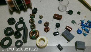
Edited in some pics
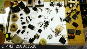   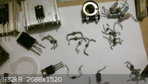
1)Some of the parts recently ripped off boards.
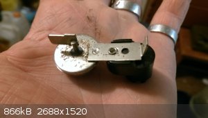
2)weird diode
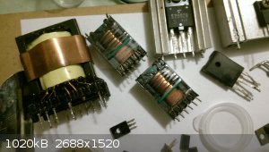
3) 3 transformers from the same board, had a pile of 2.2kv ceramic caps too
4) sintered glass diodes, byv76, byw 34-tfk, some with 228-ph end. Kinda cool, haven't seen them often.
[Edited on 24-2-2016 by violet sin]
|
|
|
woelen
Super Administrator
Posts: 7976
Registered: 20-8-2005
Location: Netherlands
Member Is Offline
Mood: interested
|
|
My ZVS driver never was pushed to the limit. It only has seen 13.8 Volts at input, simply because I have no other sufficiently powerful supply.
I found the following on eBay in increasing price:
http://www.ebay.nl/itm/390628047656?_trksid=p2060353.m1438.l...
http://www.ebay.nl/itm/222014819487?_trksid=p2060353.m1438.l...
http://www.ebay.nl/itm/161856625044?_trksid=p2060353.m1438.l...
These all are 24 volts units, capable of delivering large currents of 15 ... 20 A. Could these be used safely with the ZVS-driver? These are switched
power supplies. My 13.8 V unit is a big and heavy transformer, with a simple 4-diode rectifier, a huge 47000 uF capacitor bank, a handful of big
2N3055 transistors and a LM723 regulator circuit. Very robust old technology, which can withstand quite some abuse.
I once made a nice 12 V and 5 V power supply from a PC's ATX power supply:
http://woelen.homescience.net/science/chem/misc/psu.html
This thing worked very well for electrolysis experiments and was very robust in terms of overloading it with low resistance or even shorting it, but
when I did my first high voltage experiments with a small 15 kV DC power supply, salvaged from an old monitor, it quickly died. I did only draw a few
hundreds of milliamps from the 12 V terminal. I am afraid that some low power, but high voltage statics destroyed some sensitive CMOS circuit in the
power supply. Could this also happen when I want to use the 24 volt unit with switched regulator for my ZVS driver?
|
|
|
IrC
International Hazard
Posts: 2710
Registered: 7-3-2005
Location: Eureka
Member Is Offline
Mood: Discovering
|
|
While yes it is possible you could hurt one with transients from the ZVS I doubt you will have any problems so long as you stay within the current
ratings of the supply. You could if concerned build some sort of spike suppressing circuit on the DC input side of the ZVS to help protect the supply
but I really doubt you have to worry.
"Science is the belief in the ignorance of the experts" Richard Feynman
|
|
|
WGTR
National Hazard
Posts: 971
Registered: 29-9-2013
Location: Online
Member Is Offline
Mood: Outline
|
|
| Quote: Originally posted by woelen | | This thing worked very well for electrolysis experiments and was very robust in terms of overloading it with low resistance or even shorting it, but
when I did my first high voltage experiments with a small 15 kV DC power supply, salvaged from an old monitor, it quickly died. I did only draw a few
hundreds of milliamps from the 12 V terminal. I am afraid that some low power, but high voltage statics destroyed some sensitive CMOS circuit in the
power supply. Could this also happen when I want to use the 24 volt unit with switched regulator for my ZVS driver? |
I've done it before myself. I was powering a circuit that created high energy transients, and managed to break two expensive power supplies, even
though I had the outputs current limited. There were some transistors inside that shorted out; once these were replaced, everything worked fine again
(but I didn't use them again for that ill-fated application). If enough high frequency noise makes it back into the power supply, these kinds of
things can happen.
As IrC mentioned, it's possible to filter out the noise. The exact filter network requirements depend a lot on how fast things are switching, and how
much energy is involved.
|
|
|
WGTR
National Hazard
Posts: 971
Registered: 29-9-2013
Location: Online
Member Is Offline
Mood: Outline
|
|
Violet sin, it looks like you took apart a UPS. I recognize some of the silicon and magnetics. Those glass diodes are actually
pretty useful for high voltage work. They are avalanche diodes, and are designed to survive over-voltage events that would destroy ordinary diodes.
Basically, they are like high voltage zener diodes. You can safely stack several of them in series to get higher voltage ratings, like when you're
trying to rectify high voltages.
|
|
|
IrC
International Hazard
Posts: 2710
Registered: 7-3-2005
Location: Eureka
Member Is Offline
Mood: Discovering
|
|
Forgot to mention woelen but get the largest supply if it is within your budget. Better to have too many potential amps and not need them. You may
later scale up some project forcing you to yet again go shopping. Most importantly a supply loafing outlasts one running at the edge, and if you blow
it you will now have paid nearly double the cost of the larger supply. Since if the first purchase failed, you must add that loss in money to the
price of the larger replacement supply. Far cheaper to pay a little more in the beginning and not need to go shopping later.
"Science is the belief in the ignorance of the experts" Richard Feynman
|
|
|
violet sin
International Hazard
Posts: 1475
Registered: 2-9-2012
Location: Daydreaming of uraninite...
Member Is Offline
Mood: Good
|
|
not much love from my project just got in some lower watt zeners 12/18v, the
right 2W resistors, IFRP460's and some other non related bits.
I tried with the correct value resistors, but perhaps some of the components were more damaged than my multimeter led me to believe? no arc's issued
forth, no hum of flowing electricity, but no smoke/heat either. all ambient temp. just does NOTHING. ATX PSU isnt dropping dead when connected,
measured correct voltage on rail so no Vdroop, quick amperage test showed pleny( and quickly warmed test leads). next up is winding a better
inductor with thick wire, looking for better caps, and redesigning my PCB ( the main reason it's unattended ATM ). not that this one is bad, just
want a batter parts packing geometry for an easily packaged unit. a guy doesn't need too many 'random bits on board' type projects dumped in a box
for use *sometime* in the future.
there is a LOT to learn about the various semiconductor parts available... soo much reading. projects on the table now are LED desk lamp(95% done),
some sort of power supply to take abuse ( instead of the 70$ ebay unit I love), understanding and attempting to build my own custom LED driver for
nightlights.
basically my time now is spent on electronics projects and research, instead of chem. got a note book for documenting the process, starting from
small simple units around the house and from ebay. 200W scr dimmer, CFL bulbs, 3w led driver, motion detector light sensor, kids toys etc. sketch
the circuit, read, understand and fix if possible. if not you learn stuff. then I will get back to the harder stuff like the stepper driver I failed
miserably on.
just easier for me to mess with electronics right now then chem it up at home, and I always went back and forth any way every couple months or so.
funny little side note, I tried to get a spec sheet for an 8-pin BP9011 chip(on the 3x 1W CC LED driver) from an alexpres seller. the part is not
listed in any datasheet search engine, assuming it is a generic overseas chip name instead of the proper manufacturer designation. anyway, he quoted
me 10$ ea for the chips, couldn't provide a spec sheet and said only "if the part number is the same it will work".. meanwhile the whole led driver
costs 1-2$ US on ebay with free shipping, LOL . they do have great prices on triac's of considerable power though
|
|
|
| Pages:
1
2
3
4
5 |
|


