| Pages:
1
..
3
4
5 |
woelen
Super Administrator

Posts: 7976
Registered: 20-8-2005
Location: Netherlands
Member Is Offline
Mood: interested
|
|
Just for the fun, I built a second ZVS driver with two 0.47 uF capacitors in the capacitor bank (the other driver has one 0.33 uF capacitor). The new
one draws really impressive arcs, when powered with a 13.8 V / 30 A supply. These arcs easily reach a length of 3 or 4 cm and they are thick and hazy
(3 mm wide) and have a warm-white color instead of the typical bluish cold/white of sparks. Ignition occurs at a cm or so, once ignited, I can move
the electrodes away from each other and then the arc becomes fat and noisy.
Also very strange is the noise made by the arcs. They make a whining noise, nearly like unsteady whistling. It definitely is a tone and not just
noise. I never heard this before with small arcs.
|
|
|
IrC
International Hazard
Posts: 2710
Registered: 7-3-2005
Location: Eureka
Member Is Offline
Mood: Discovering
|
|
"I never heard this before with small arcs."
I imagine it is because of the much greater current in the arc which means be careful these things are above average dangerous.
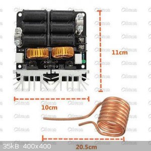
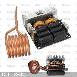
On that subject my 1,000 watt ZVS came in the other day, even comes with the copper coil for melting metal in a crucible placed inside the coil. All
for ~$29 shipped.
Edit to add: Don't even think about driving a flyback with this one it will be vaporized. Trying to run the board down to 5 or 6 volts to keep from
destroying the flyback fails because the ZVS needs 9 or higher volts to start reliably and if it does not start instantly you have a dead short on the
input supply. At 9 volts I destroyed one of my real nice $30 flyback's. Internal arcing in the potted HV winding section until a crack and smoke
appeared. For a few seconds it sure put out one hell of an arc.
[Edited on 3-11-2016 by IrC]
"Science is the belief in the ignorance of the experts" Richard Feynman
|
|
|
Metacelsus
International Hazard
Posts: 2531
Registered: 26-12-2012
Location: Boston, MA
Member Is Offline
Mood: Double, double, toil and trouble
|
|
Wait:
1000 watts? $29?
What kind of transistors are those (and can I get some)?
(Although, the low cost might be due to the company that makes the boards buying the transistors in bulk.)
|
|
|
IrC
International Hazard
Posts: 2710
Registered: 7-3-2005
Location: Eureka
Member Is Offline
Mood: Discovering
|
|
Quote: Originally posted by Metacelsus  | Wait:
1000 watts? $29?
What kind of transistors are those (and can I get some)?
(Although, the low cost might be due to the company that makes the boards buying the transistors in bulk.) |
You are thinking about it incorrectly. The important parameters are small conduction angle and milli-ohm junction resistance keeping dissipation so
low the two hexfets easily handle kilowatt power levels.
Also, it was on a reduced price sale just over a month ago that had a couple days left when I saw the auction so I grabbed it. It took 6 weeks to
arrive, I imagine their $2.80 epacket is around 12 days shipping time.
http://www.ebay.com/itm/141837935864?_trksid=p2057872.m2749....
Today it is $35.59 plus $2.80 shipping. They probably have sales on it every so often so keep checking current listings.
"Science is the belief in the ignorance of the experts" Richard Feynman
|
|
|
violet sin
International Hazard
Posts: 1475
Registered: 2-9-2012
Location: Daydreaming of uraninite...
Member Is Offline
Mood: Good
|
|
@ IrC: That is pretty sexy! Nice find, I can see some money I don't yet posess being spent in the near future. Perhaps some sillicon carbide
material too 
Obviously a larger machine built at home would be 1000% more gratifying than purchasing one. But man you can't beat the price on that guy and the
experience it would offer, and it would you get a sense of the eventual power one might need. Even if you could only melt small bits of metal, custom
copper heatsinks from electrical wire scrap = happy. Silver scrap to electrode slugs, small crucibles from nickel poured and pressed in a crucible
mold, shoot maybe even succeptor loaded catalyst support in a quarts tube?
Thanks for sharing.
|
|
|
woelen
Super Administrator
Posts: 7976
Registered: 20-8-2005
Location: Netherlands
Member Is Offline
Mood: interested
|
|
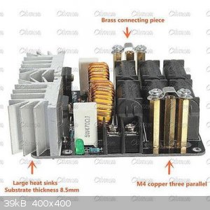
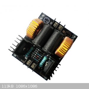
I see 6 capacitors on the board and two toroids. Is it a standard ZVS driver? Or is this just 6 capacitors in parallel and toroids in parallel? What
total capacitance does it have? Apparently the board has two IRFP260 transistors.
Could you please tell something more about the properties of this circuit? For this price of appr. EUR 30 and free shipping it sounds too good to be
true for me. This really is a bargain and I am tempted to order one, but I want to be sure it is not some fake crap (I still am somewhat wary of
ordering such cheap electronics from China).
[Edited on 11-3-16 by woelen]
|
|
|
Metacelsus
International Hazard
Posts: 2531
Registered: 26-12-2012
Location: Boston, MA
Member Is Offline
Mood: Double, double, toil and trouble
|
|
It's interesting that it uses IRFP260 transistors. I actually happen to have those ones in my homemade ZVS driver, but I've never been able to take
the power above ~250 W without serious overheating problems. This is enough power to make a nail glow orange and become somewhat soft (or to nicely
power a flyback) but not to melt metal.
@IrC: I know the point of a ZVS circuit is that the transistors don't need to handle the full 1000 W, and that low junction resistance is crucial.
However, I'm still impressed at the power.
|
|
|
IrC
International Hazard
Posts: 2710
Registered: 7-3-2005
Location: Eureka
Member Is Offline
Mood: Discovering
|
|
So far outside of the circuit running at very high power the only thing I have found not in agreement with info on the auction page is mine draws much
more current than they state. At 14 volts using the supplied Cu coil it draws 27 amperes, no way is it going to be 20 amperes at higher voltages as
the item listing info states. Also it draws 8 amps idling with Cu coil removed at Vcc = 14 volts, loaded with a higher impedance coil (the primary
side of a transformer as load). They mention at higher powers you must supply a fan for the heat sinks on the board. Woelen I will have to physically
trace the circuit to answer your questions. I will do the best I can but I may have to remove parts to do so. I will get back to you on that. If it
helps, all the parts on the board are standard ZVS values. I will try to trace out the chokes, caps, to answer your concerns. It does run at high
power and works great for melting flybacks so I do not think that is a good idea unless some alterations are made. As to metal melting I cannot try
yet. My big supply is in my storage and I cannot bring it in. Been fighting pneumonia for 2 months and just do not have enough wind to go digging it
out and bringing it in to the bench.
All I have in here is a 36 amp 14 volt supply and it trips the over-current warning with the Cu coil. Also gets my power supply too hot. I have
concluded a variable switching supply is going to be mandatory to run this board up in power. My Iron transformer/pass transistor old style supply
just cannot handle this board. I have a similar style in a 60 amp Samlex in storage I want to try. However I think even it cannot handle this board
for long metal melting times, going to search online for a 150 amp switching style. Back to the very question a few posts above. There is just too
much dissipation loss/heat in the bipolar pass transistor type supply to run this thing. My PS36K uses 8 TO-3 pass transistors and at 27 amps steady
for a minute or more they are too hot for my taste. Only reason I always liked these types was I can repair them easily whereas with the switching
designs usually the odds of repair is low. No one sells a model that provides any schematic or service info and that is why I always shied away from
them. I like to be able to fix and maintain what I use. What is needed is a 100 amp min. switching supply that can be adjusted from 12 to 48 volts
with an adjustable current limit to keep the board from drawing too much.
"Science is the belief in the ignorance of the experts" Richard Feynman
|
|
|
violet sin
International Hazard
Posts: 1475
Registered: 2-9-2012
Location: Daydreaming of uraninite...
Member Is Offline
Mood: Good
|
|
That's funny you mention samlex, just talking with my father last night about power supply types and demands I might face. He mentioned I should
check into "sanlex" for a nice switching type selection phone was cutting out so I spelled it wrong. Thnx for the correction there.
I have read that the two toroid version is designed to overcome the centertaping the work coil, which is usually water cooled. Be nice and easy to
plumb that bit in right? I imagine it would be hard to equally split the supplies to each half of the work coil assuming you used the CT as intake
and either end as exhaust water.
Samlex 3000-48 looks nice. 3000W ~62A 48V, adjustable to 20%-120% so 9.6-57.5V BUT it's like 400$+ unless you want to contact samlex with a quote
request. I found the Google prices telling enough, no need to inquire
[Edited on 12-3-2016 by violet sin]
|
|
|
IrC
International Hazard
Posts: 2710
Registered: 7-3-2005
Location: Eureka
Member Is Offline
Mood: Discovering
|
|
Had to pull both chokes and all 6 caps to trace out the circuit board. Each output post is on one drain, each drain also through its own 100 uH toroid
to the + rail. All 6 caps in parallel yielding 1.98 uF 630 Vac, from post to post (which amounts to ~2 uF drain to drain). That's it, rest is like any
other ZVS circuit except no center taped coil required, just a single coil. Also this method halves the current through the choke compared with a
typical Mazzilli design. In effect a separate choke to each drain and no need for a center tapped coil load is the only deviation from any typical
design we have seen, that and the larger capacitance drain to drain.
So I may not put all 6 caps back in mine as the current draw was very high and I have already learned by experimenting that the lower the capacitance
the lower the current draw. Merely have to compromise with whatever max power I want it to do. If it still melts metal with only 2 caps back in it
will do so at less than a third the amp draw as using all 6 caps. Far as I know Samlex made brute transformer supplies back in 80's and 90's, but I
guess from your post they do make switching supplies so that is good I have always liked my 60 amp for radio work but it uses bipolar pass transistors
and they just get too damn hot for this ZVS stuff. Switching supply is I think mandatory for these circuits.
Woelen it is not a fake, just altered to run from a single coil omitting the center tap. I do not like the huge amps it pulls so I think a supply with
adjustable current limit is a must. Also it oscillates fine (idles) with no coil attached to the posts, around 7 or 8 amps at 14 volts. However after
putting it all back together and testing to be sure it still works I found it generates high voltage sparks from posts (drains) to ground, no doubt
back EMF from the 100 uH toroids. This could blow the fets so I advise having a coil load always connected to eliminate this possibility. One last
thought is the sinks are just not enough even with a fan if metal melting high power for a length of time is contemplated. To increase the thermal
connection they omit hardware with the drains in contact electrically meaning they must be isolated fet to fet.
So obviously replacing the two sinks with one much larger will not work without insulators which will make thermal conduction lower. I do not see a
way around this unless the board was mounted in a case with room to mount two much larger sinks each with a fan, sinks isolated electrically. Also a
decent gauge wire to connect the fets back to the board would be needed, as short as possible. From all this I conclude to use this board at very high
voltage and power level for several minutes I would want to go with outboard larger sinks/fans, parallel well matched fets to increase the power
ratings (hoping the circuit starts properly). All in all quite a project so I'm not so sure as a metal melter I like this board, it is at lower
voltage/power an astoundingly powerful flyback (or other transformer) driver just as it is built. I think for metal melting I would rather spend time
looking at the site of Tim (12AX7) and build his project.
Lately I have been toying with the ZVS and hand wound ferrite transformers to drive sheets of Barium Titanate, call it a poor mans LRAD. I can see
this board is going to be great for this and I no longer need to make center tapped primaries. So I'm happy with this board even if their metal
melting claims may be overstated. Not saying it will not work, I just think overheating will be an issue. After two days doing experiments I am
somewhat as skeptical as Metacelsus concerning the kilowatt claim, especially at durations long enough to be useful in melting metals. Mind you it
could be I got a poor one since as I stated above "mine draws much more current than they state". Is it due to one or both fets having excessive R
ds(on) or are they exaggerating their specs? I am not sure. I only went to this much testing and depth of study to give Woelen the best opinion I can
before he invests in one.
What is the use you are considering for the board Woelen, is it metal melting? If so I am not sure. If your intended use is a fairly powerful high
voltage transformer driver then yes this thing kicks ass. Not however at the 24 to 36 volts they mention, as I said mine draws 27 amperes at 14 volts,
gets hot fairly fast with no fan and this is only in the 400 watt range. It does do better driving a higher impedance load than the Cu tubing coil it
comes with but even with fans I do not think I would trust it above 5 or 6 hundred watts. I am happy with the board for the uses I have in mind so for
me a good purchase I think.
"Science is the belief in the ignorance of the experts" Richard Feynman
|
|
|
woelen
Super Administrator
Posts: 7976
Registered: 20-8-2005
Location: Netherlands
Member Is Offline
Mood: interested
|
|
IrC, thank you very much for putting all this effort in analyzing the circuit. It is good to know that it is not fake and I think I will order one. I
will not use it for melting, as you suggest, but it can be very interesting as a driver for a flyback transformer (with 10 to 12 turns, single strand,
primary).
|
|
|
WGTR
National Hazard
Posts: 971
Registered: 29-9-2013
Location: Online
Member Is Offline
Mood: Outline
|
|
| Quote: Originally posted by woelen | | Also very strange is the noise made by the arcs. They make a whining noise, nearly like unsteady whistling. It definitely is a tone and not just
noise. I never heard this before with small arcs. |
https://www.aps.org/publications/apsnews/201012/physicshisto...
Or, if one wanted to do this at higher frequencies and power, old VLF transmitters used a Poulsen arc converter. It was a really clever way of
generating continuous signals before vacuum tubes were up to the task.
|
|
|
woelen
Super Administrator
Posts: 7976
Registered: 20-8-2005
Location: Netherlands
Member Is Offline
Mood: interested
|
|
EUR 100 power supply blown out
Yesterday I blew out my 10 A power supply with the ZVS driver  . It is a big and heavy linear power supply with a big transformer. The only thing
which still works is the transformer and the bridge rectifier with capacitor bank and power indicator, all other electronics is totally dead. This
cost me EUR 100 or so. At the back of the power supply there are a few big transistors in TO-3 package, I cannot see their type number. They also are
dead. Maybe they are 2N3055 and/or 2N2955 transistors. . It is a big and heavy linear power supply with a big transformer. The only thing
which still works is the transformer and the bridge rectifier with capacitor bank and power indicator, all other electronics is totally dead. This
cost me EUR 100 or so. At the back of the power supply there are a few big transistors in TO-3 package, I cannot see their type number. They also are
dead. Maybe they are 2N3055 and/or 2N2955 transistors.
The ZVS driver itself still works. If the flyback transformer is connected to it and between the output leads of the transformer I hold an ampoule of
low pressure neon gas, then the total current drawn is only 600 mA at 13.5 volts input and the ampoule glows orange, but when arcing it draws very
high current.
|
|
|
careysub
International Hazard
Posts: 1339
Registered: 4-8-2014
Location: Coastal Sage Scrub Biome
Member Is Offline
Mood: Lowest quantum state
|
|
| Quote: Originally posted by IrC |
On that subject my 1,000 watt ZVS came in the other day, even comes with the copper coil for melting metal in a crucible placed inside the coil. All
for ~$29 shipped.
|
This seems to be one of two 1000 W ZVS designs available from China for about the same price. The other is this one.
Any known reason to choose one over the other?
I am interested in making a metal melter, probably using those cheap 30mm x 40mm graphite crucibles on eBay, which have a 10 mL volume, wrapped in
ceramic paper insulation. You could also roll your own graphite molds/crucibles by drilling/sawing/carving graphite blocks - it is quite soft but
messy.
Since the copper work coil will be water cooled anyway, I am planning on replacing the MOSFET heatsink with a water cooled one, and using ice water
during heating runs. With the one I show here, this would require two water cooler sinks obviously, a small complication. Another possibility for
cooling - simply immerse the whole thing in oil?
I have a variable voltage and amperage DC power supply rated for up to 30 V and 10 A, but for 48 V high power runs I am planning on using four 12 V
lead-acid batteries, which would be cheaper than the 48 V 1000 W DC power supplies I see, and immune to overload (also gives me 12 V, 24 V, and 36 V
configurations). 10 AH batteries would be good for 30 minutes at close to full power, I imagine melting runs are pretty short.
Normally stuff that oxidizes could be melted under flux in the crucible, but it would be interesting to put the coil inside a CPVC tube to be able to
operate under argon. With good insulation plugs above and below, and since the coil is water cooled, I think this would work.
[Edited on 17-7-2016 by careysub]
|
|
|
Freelance
Harmless
Posts: 2
Registered: 20-8-2017
Member Is Offline
Mood: No Mood
|
|
^^
Not being rude, if you read IrC's post on 12-3-2016 at 02:17 it seems the more caps, simply the more amp draw. It seems obvious to me that you want to
avoid the "more is better" visualization when picking these 1000w boards. Unless you have a very expensive power supply (more amps at high voltage)
your best bet is to get a small board with 2x caps, check all solder points (shipping can break or loosen them), check for good mosfet connections,
add a fan immediately, and possibly look into a better heat-sink (and maybe use extra heat transfer paste).
I've been doing days and days worth of reading on the internet before making my purchase; that will likely happen next week. There's a wealth of
knowledge all scattered across the internet. I'm not an electrical engineer but will rely on the posters above to guide.
IrC, since I've self admitted to being a newb can you advise as to sticking with the equipped caps, mosfets, ect... on the board or do you think
there's some that would/could/should be upgraded? I'm going to buy a 2x cap board, and use Litz wire for my application. I'm only heating objects to
40°C and tops 110°C so I'm now working on how to PWM the board. Perhaps a relay before the ZVS between the power supply will work best. This should
avoid momentary low voltage from the power supply (I'll have many, many voltmeters tracking the whole system)?
Thanks for all the posts guys! It's been very helpful....
|
|
|
woelen
Super Administrator
Posts: 7976
Registered: 20-8-2005
Location: Netherlands
Member Is Offline
Mood: interested
|
|
This is a real bargain:
http://www.ebay.com/itm/5Pcs-DIY-ZVS-Tesla-Coil-Power-Supply...
5 drivers, PCB's and all parts needed to build the driver. You can, however, replace some components by even better ones (e.g. use even lower resistor
transistors), or use other capacitor values.
This allows one to experiment with these beasts and blow out one of them without too many consequences in terms of cost or being out of testing
devices after a single failure.
|
|
|
Freelance
Harmless
Posts: 2
Registered: 20-8-2017
Member Is Offline
Mood: No Mood
|
|
Anyone see this newer (lower output) board? Seems to have some more protection features on the board.
http://www.ebay.com/itm/20A-ZVS-Induction-Heating-Board-Flyb...
I'm thinking this one is better for my application as it will protect itself and I'm not requiring 1000w heating rate. If they accept my offer I'll be
playing with some PWM soon enough.
Any new ideas or thoughts on induction systems???
|
|
|
| Pages:
1
..
3
4
5 |


