| Pages:
1
2
3
4
5 |
IrC
International Hazard

Posts: 2710
Registered: 7-3-2005
Location: Eureka
Member Is Offline
Mood: Discovering
|
|
http://www.ebay.com/itm/Pancake-Style-Unrectified-AC-Flyback...
If anyone needs a really great flyback for various experiments this link is the last place I can find still selling this type. Somewhat high price but
no other flyback comes close to the output voltage and current I have been able to get from these. 7 left, 8 sold in 24 hours so I would say they are
going fast. Now days this is a rare find and not comparable to the TV or monitor specific models which are very inferior to this one. Was hoping this
person would know what these were originally for but states on the page they do not know. The surplus place I got mine from did not know either so it
is a mystery. Such information may have been helpful in locating more. If anyone recognizes it post the information, I would love to get more of
these. I used one to make the most impressive Marx Generator I ever built (yet another project soon to be powered by a ZVS circuit). The secondary is
1.5" tall by 2.75" diameter with a very thick HT output lead. It comes apart easily making winding various primaries a simple task.
One left.
[Edited on 7-25-2014 by IrC]
"Science is the belief in the ignorance of the experts" Richard Feynman
|
|
|
Metacelsus
International Hazard
Posts: 2531
Registered: 26-12-2012
Location: Boston, MA
Member Is Offline
Mood: Double, double, toil and trouble
|
|
Man, those things are going fast! I just bought one.
|
|
|
IrC
International Hazard
Posts: 2710
Registered: 7-3-2005
Location: Eureka
Member Is Offline
Mood: Discovering
|
|
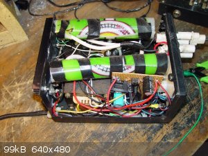    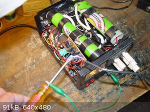   
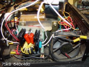
I reduced the images to 640x480 to avoid going past the post limit.
Seems interest in this thread has vanished lately, I wonder if woelen has built his ZVS circuit yet?
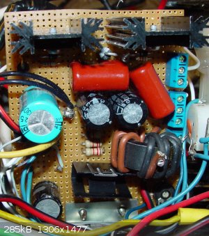
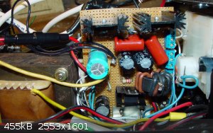
Anyway, the pics show a supply I built back in 2004. I would also post a schematic but after a decade I don't know where it is buried in my junk. Not
really needed, anyone even slightly skilled in the art can see how straightforward this circuit is. To be honest a diagram is not really needed.
Similar to what Tim posted a couple pages back and the supply is just a 2 watt 10K potentiometer (top 25 volts, center base, bottom ground) driving
the base of a Tip3055 which drives a 2n3055, with a few capacitors here and there. Powered by a 19 Vac 12 ampere transformer into a 50 ampere 100 volt
bridge (giving full wave output) which loaded at a few amperes gives a steady 25 volts DC output filtered by a few thousand uF. One 2N3055 is the low
voltage DC power supply pass transistor, the other two each drive a flyback of the type in the top post on this page. Been 10 years since I looked
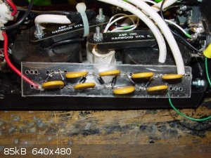
inside this supply, at least I got my answer as to who made them it's on the top of each flyback (pic 7a). The circuit board: one Tip3055 drives the
power supply 2N3055, allows me an adjustable zero to 25 volts which can do 8 amperes all day and probably 2 or more times that for shorter durations,
until I lose the 2N3055 that is. The 555 circuit is on a separate Zener regulated 12 volt circuit, it drives another Tip3055 which drives the other
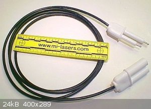
two 2N3055's. You can see them on the circuit board each with a clip on heat sink. Each flyback primary is opposed in phase. The last pic is the type
of He-Ne connectors I used, made by Alden.
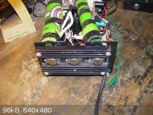
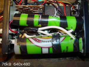
Circuit ground and chassis ground are one, connected to the banana jack in front (and AC plug ground). From this I get half the maximum potential to
each connector. One port on each plug (bottom) is the AC high tension from a flyback (~17 KHZ), the other (top) is from the multiplier. So from
connector (bottom) to connector (bottom) I get double the AC high voltage on bottom, and double the multipliers on top. Each multiplier is enclosed in
a cylinder of fairly thick plastic (rolled up 54 oz plastic soft drink cup). These worked well, never once in a decade have I ever had any arcing
inside. I opened one up so one of two identical plexiglass mounted multiplier circuits is visible. All in all this has been for years a very useful
0-100 KV adjustable supply for various mad-sci experiments.
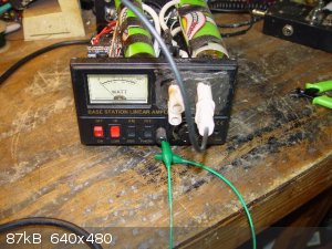
Showing the before as it is now. It works as I designed, was going for a zero to 50 KV to ground from each connector and double that between
connectors. Just wanted to show the before as next I am going to take out the electronics and rebuilt this as a ZVS driven supply. I will parallel all
three 2N3055's for the zero to 25 volt supply at greater current rating. Needed for a ZVS driver circuit. May take a few weeks in my spare time but I
am curious to see the final output comparison between this 'typical' circuit and a ZVS version, all other things being relatively equal. Still giving
thought about how to drive the flybacks. I want them running 180 out from each other so I can still utilize the double the AC high voltage output.
While not important for the multiplier outputs, I want double the AC high tension from the flyback windings from plug to plug. If you look at the plug
in pic 5a, the center is the multiplier and the shield is the direct flyback secondary out. The reason for this was so that I can use the supply to
drive other multiplier (or whatever) circuits as opposed to using the internal multipliers.
Seems difficult to have two independent ZVS circuits synchronized. This leaves me thinking I should rewire the primaries, make them identical, drive
them opposing in parallel from a single higher rated version of a single ZVS circuit. Any thoughts from people as to how I can best approach this
concept?
Forgot to mention but the only arcing problem I had was the Alden plugs are not rated for 50 KV. I overcame this by cutting out a big rectangle in
front, filling the space with a plexiglass window drilled for the connectors and epoxied in (makes it little ugly but no problem for me I just wanted
a trouble free HV supply). The meter indicates zero to 25 volts output from the pass transistor (now all three in parallel as I have rebuilt it
tonight since I no longer need the other two 2N3055's for running flybacks). The Alden plug on the left top comes from a negative multiplier stage and
top right plug comes from a positive multiplier stage. In this way I could double the high voltage output. Basically a 100 KV supply grounded in the
middle for a true dual polarity setup. I have on occasion found this arrangement to be useful in some experiments.
I write this while taking a break from it, I just finished removing all the 555 circuit components to give room to build the ZVS circuit on the same
board. Saves time as I already have it setup with bottom bracket to mount to the floor of the chassis. For now I will try driving two 10 turn CT
primaries (opposite phase on each flyback as I still want the AC outputs to double plug to plug) in parallel from a single ZVS circuit. Not really
sure how this will work out but if it does it will save time and parts, space as well. Thought about using the factory made ZVS board but I decided to
leave it for my metal melting coil. Dug out my 50 volt 50 ampere supply and even with my larger coil it works well enough. Have not gone above 25
volts, no point in blowing up such a nicely made board and it states 36 volts maximum.
[Edited on 8-3-2014 by IrC]
"Science is the belief in the ignorance of the experts" Richard Feynman
|
|
|
IrC
International Hazard
Posts: 2710
Registered: 7-3-2005
Location: Eureka
Member Is Offline
Mood: Discovering
|
|
If I needed proof of concept I guess I have it. Found the single 2N3055 in the rail was leaky from past operation over the years from cranking it wide
open. At that point it drew about 11 amps at 22 volts (loaded) powering the two 2N3055's driven by the pre-driver transistors, in turn driven by the
555. I had optimized frequency and duty cycle through many trials for highest voltage out from the flybacks. All in all it worked well and I never had
problems with arcing in the two multipliers. Replaced all 3 power transistors with a fairly well matched new set putting them all in parallel to serve
as just the power supply. Built the ZVS circuit, 1 uF and both primaries in parallel (opposing). Not a problem as they are on different cores as far
as the ZVS oscillating goes.
I was not sure this would work properly with this circuit, but it turned out to oscillate powerfully no problem. For the flybacks I wound two
primaries, 16 turns CT, installed on flybacks in opposing phase. The original primaries were 28 turns Teflon Silver plated wire, no taps. Fired it up
and slowly adjusted the rail up from zero volts. I did not get to 14 volts on the rail when both multipliers flamed out so bad the plexiglass on each
is ruined from carbon tracks, since they will forever be arcing out now. Will need to build them all over again. Ruined several 6 KV capacitors and
many of the 200 ma 6 KV diodes. Each multiplier had 7, one plus leading out the other minus. Those 6 KV 200 ma diodes are not cheap and hard to find.
Needless to say I never got the chance to take any pics of it running. Thinking I am going to have to find two tubes with ends that will screw on and
seal to hold oil while housing the multipliers and still fit inside the cabinet. Obviously the voltage is far higher than ever before and I will have
to reduce the number of multiplier stages. I should have set up 2 spark gaps to load the positive and negative outputs before I began operation but it
never occurred to me the voltage output would be so much higher the multiplier stages would start vaporizing.
Bottom line is there is no doubt the ZVS circuit is a radical increase in power into the flybacks compared to all the circuits I have used for years.
I believe the operating frequency is too low meaning I will need to roughly halve the 1 uF in there now to raise the frequency. I deduce from the
sudden current increase in the rail around 10 or 12 volts the flyback cores are saturating. Did not have time before I lost my multiplier stages to
look at waveforms but clearly the flyback cores are beyond magnetic saturation, with a waveform far removed from a nice sine shape. This I must do in
order to protect the power supply from an excessive current overload. I used a pair of IRFP260's (saving my ten IRFP264's for other projects), also
two each of 600 ohm 1W, 12V1W Zeners, MUR460 high speed diodes. Typical circuit as woelen first posted except for the 1 uF 630 volt film capacitor and
also running a dual set of primaries. Still waiting for my 3W 470 ohm MF resistors so had to settle for close and on hand values. The circuit did not
seem to mind the increase from 470 to 600 ohms as far as it goes.
In any case clearly the ZVS circuit is the way to go for driving flybacks if one considers using higher ratings and fewer stages in the multiplier
output section. I will take a few pictures after I rebuild the multipliers. Problem is high voltage diodes and capacitors are getting more expensive
and harder to find unless one wishes to ream their pocketbook at Digikey or some similar source. Takes longer but I much prefer buying surplus deals
in greater quantity at lower cost.
"Science is the belief in the ignorance of the experts" Richard Feynman
|
|
|
woelen
Super Administrator
Posts: 7977
Registered: 20-8-2005
Location: Netherlands
Member Is Offline
Mood: interested
|
|
I am back from holidays (nearly two weeks without decent internet access, hence the apparent loss of interest in this subject) and in the meantime my
IRFP's arrived and some diodes as well. I also have 1 uF capacitors and 0.47 uF capacitors, rated at 630 volts and 250 volts. So, I think I can build
the circuitry. I also have a nice little PCB which can hold all the components of the ZVS driver. One of these days I will try to build the circuit
and I'll report back on my results.
|
|
|
IrC
International Hazard
Posts: 2710
Registered: 7-3-2005
Location: Eureka
Member Is Offline
Mood: Discovering
|
|
I added another 1 uF 630 volt cap in series to give 0.5 uF 1260 volt rating. Current flow dropped significantly. Oscillation starts at a lower voltage
and output voltage increased quite a bit. No doubt the flyback cores were saturating badly. This is with both flyback primaries (each 16 turn CT) in
parallel but 180 phasing. No way to measure the AC voltage between flyback secondaries but it is amazingly high. Much higher than before at 1 uF. The
circuit runs cooler and more stable. Looking at the pics, the 260 fet on the right runs cool the left hand one slightly warm. Everything else runs
cool except the three 2N3055's but they are heatsinked well and within temperature tolerances. The trimmer bottom right adjusts the voltmeter (was a
watt meter in another life of the chassis). The transistor at bottom in clip on sink runs the three parallel 2N3055's.
At this point I must stop, I cannot find what I need to build two multipliers and encase them in oil while still all fitting in the cabinet allowing
me to put the top cover back on. I need just the right tubes (to enclose multipliers yet hold oil), and capacitors, diodes with higher than 6 KV
ratings.
Well my wandering the hardware and grocery stores did no good. Found some items with plastic tubes yet metal lids. Must be all plastic with screw on
top so I can drain, rebuild multipliers if need be. Without gluing the end caps on. Must be 6 or 7 inches long and around 2 inches diameter, but no
more so they will fit in cabinet. I guess I could encase them in RTV but self healing is important for long term reliability meaning oil is better.
[Edited on 8-4-2014 by IrC]
"Science is the belief in the ignorance of the experts" Richard Feynman
|
|
|
woelen
Super Administrator
Posts: 7977
Registered: 20-8-2005
Location: Netherlands
Member Is Offline
Mood: interested
|
|
In my previous post I forgot to add some interesting information. For people wanting to build the ZVS driver, buying a pre-etched little PCB may be
interesting and useful. I purchased this (and some other goodies, such as high voltage wires and resistors) and received this during my holidays:
http://www.ebay.nl/itm/Leiterplatte-fur-ZVS-Driver-Hochspann...
I am in the process of building my driver with this PCB.
[Edited on 5-8-14 by woelen]
|
|
|
IrC
International Hazard
Posts: 2710
Registered: 7-3-2005
Location: Eureka
Member Is Offline
Mood: Discovering
|
|
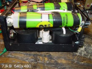
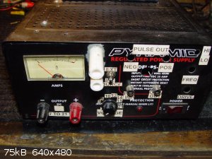
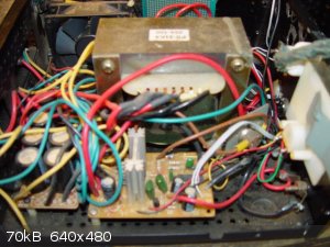
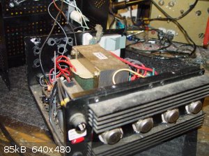
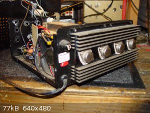
Being stuck on the dual supply until I can rebuild the multipliers I decided to alter another supply I built long ago to a ZVS driver design. This one
outputs only the AC high voltage at around 17 KHZ. The first 5 pics are what it was, originally starting as a 21 amp power supply. I modified the
LM723 circuit so the pot would adjust the output from 7 to 21 volts and used the old 555 circuit plus transistors to drive the flyback (which when
together mounts upside down to the top cover). From the labels and holes you can tell it has been quite a few different projects over the years. I
kept one RCA jack for frequency and waveform measurements.
   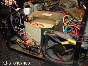  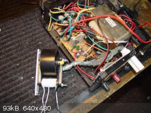  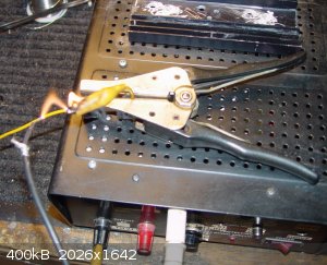
Pic 6 shows the flyback primary rewired from 28 turns to a CT 14 turn coil. Pic 7 shows the ZVS board built in place of the old 555 circuit. Pic 8
shows it all put together and operating at 21 volts while it sets the alligator clip insulation on fire. I ran it for a long time wide open at 21
volts melting and burning away with no trace of overheating or problems. Outstanding performance. This supply was for running external multipliers or
Marx banks. Or whatever comes to mind. I used a pair of the 264 fets in this one. My 470 ohm 3 watt resistors were in so I used 2 of them. Two 1 uF
630 volt capacitors in series, at the junction of the two I run through a 47 pF 1 KV SM to the RCA jack. Hot lead grounded though 68K for a slight
load so measurements of the frequency and wave-shape will be more stable. Worked out very well and now I have a much more powerful supply.
"Science is the belief in the ignorance of the experts" Richard Feynman
|
|
|
woelen
Super Administrator
Posts: 7977
Registered: 20-8-2005
Location: Netherlands
Member Is Offline
Mood: interested
|
|
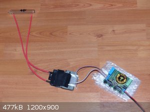
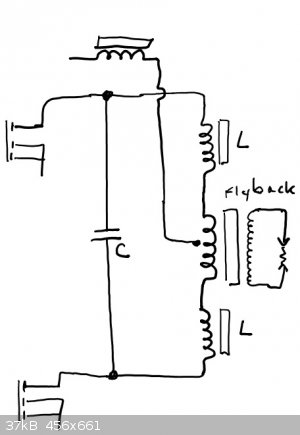
IrC, you are much further in this area than I am, but I now can show my first results with the true ZVS driver.
The circuit is shown in the picture below. I used the PCB on which I posted a link before, and a flyback transformer on which I made 2x5 turns, just
as in the standard documents about the ZVS driver. I used simple loudspeaker cable for the primary, with one side marked with a red stripe.
I do not have a really good power supply for this kind of experiments, I only have 12 V and 13.8 V fixed, max. 10 A. I took the 13.8 V power supply
and connected it to the driver.
This is a picture of the driver with the transformer and one of my element samples (neon gas in a thick walled glass ampoule).
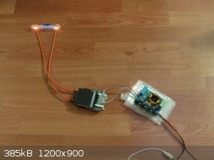
When the circuit is switched on, then the glass ampoule starts glowing orange near the electrodes and blue in the bulk of the tube. The ampoule is
quite large (total length is well over 10 cm) and even under these very unfavorable conditions I get a decent glow in the tube. This means that the
output of the driver must be at least several kV. Unfortunately I cannot measure the voltage. There is, however, a strong hissing noise and a smell of
ozone, so I think there is quite some corona discharge around the electrodes.
The transisitors in the driver do not get hot at all, the glass tube becomes quite hot and I dare not let it run for extended periods of time. I do
not want to destroy my nice sample of neon gas (I also have samples of the other noble gases in such tubes and they also glow when they are treated in
the same way). The picture below shows the circuit in action.
Next step is to draw some arcs with the driver with my 13.8 V power supply.
|
|
|
IrC
International Hazard
Posts: 2710
Registered: 7-3-2005
Location: Eureka
Member Is Offline
Mood: Discovering
|
|
Woelen have you thought about modifying your power supply to make it variable? Do you have a schematic and what model is it? Better models have a
crowbar circuit built in, you need to find out and if needed disconnect it. Otherwise when you get above around 16 volts things will blow. If you look
at my last post you can see it was in it's first life a Pyramid PS 21. A 21 ampere (intermittent) 13.8 volt supply. Since I still desired regulation I
kept the LM723 board and modified it for a wide variable. Due to constraints of the LM723 and my general laziness I opted for the very simple approach
which does not go below 7 volts. In the days of 555 timers and driving transistors this was not much of a problem. With the new ZVS circuit I am
getting several kilo-volts down at 7 volts so maybe I should rethink my laziness. Or maybe dig out a chassis mount neon and resistor to at least warn
me when it does not look like it's operating. Yes, I forgot and knocked the crap out of my stupid self last night when I was rebuilding and testing
this project.
In any case typical 13.8 volt big transformer supplies can provide 21 to 26 volts out depending upon design by modifying the circuit. This would be
better for your ZVS testing. As example my factory built ZVS which I decided to dedicate for a metal melter does not get hot (much) at 13.8 volts. In
fact I am at around 20 volts before it works at all. Still never drove it above 26 volts even though it states 36 volts max. I was using the variable
supply from the dual polarity HV project to test this. I just need to find time to dig in storage for my 50 ampere zero to 50 volt supply before I can
really drive the metal melter. If it works well I will likely build some kind of switching supply which is adjustable after first finding out what
range of voltage and current I need to melt metals without blowing up the board. If that happens at least I have plenty of ZVS circuit parts to repair
it with.
Something I forgot to mention on my post before this one: in the pic p6.jpg you can see a coat of RTV I built up on the flyback high tension lead.
When assembled the flyback mounts to the top cover upside down and just clears all the items below it. Barely fitting inside just above the LM723
regulator board. I kept hearing a corona hiss, even though the wire is nice and fat with a 40 KV rating. The RTV coat eliminated this problem. Until I
changed it to a ZVS circuit. Now it's worse than the first time obviously indicative of much higher voltage. Will have to take the cover off and try
building up an even thicker layer of RTV on the lead to the HV socket.
[Edited on 8-7-2014 by IrC]
"Science is the belief in the ignorance of the experts" Richard Feynman
|
|
|
woelen
Super Administrator
Posts: 7977
Registered: 20-8-2005
Location: Netherlands
Member Is Offline
Mood: interested
|
|
I do not wish to poke around inside my power supply. I also use it for other purposes and for those it is perfect.
I decided to buy another cheap 30 A 13.8 V power supply (they can be purchased here for less than EUR 100, second hand stuff, used by radio amateurs).
Here follows a link for a new one: http://www.okaphone.com/artikel.asp?id=441422
I also ordered two of these:
http://www.ebay.com/itm/400752051194?ssPageName=STRK:MEWNX:I...
These can be adjusted to a certain output voltage (which must be at least 2 volts higher than its input voltage) and a maximum current. If the actual
current exceeds the maximum current, then the voltage drops, so that the output current becomes equal to the maximum current. I ordered two of these.
These devices can be used in parallel, I could adjust both of them to 7 A output, 24 V and connect them to the 30 A 13.8 V power supply. They may not
draw more than 15 A from the supply. With 15 A at 13.8 volts input and 95% conversion efficiency, I can draw 0.95*15*13.8/24 A at 24 volts, which is
just over 8 A. With two modules in parallel I certainly can draw 15 A at 24 volts which should be enough for my ZVS driver.
I hope (and expect) all of this stuff together to cost less than EUR 100 together. This also gives me a flexible power supply for other purposes.
|
|
|
woelen
Super Administrator
Posts: 7977
Registered: 20-8-2005
Location: Netherlands
Member Is Offline
Mood: interested
|
|
 I put a fuse of 5 A in series with my driver, applied 13.8 V and then used the
circuit for making an arc. When I do this, then I get a fat and noisy arc for a fraction of a second and then the fuse blows out (it gives a brief
flash of light and then it is gone). I have the impression that making arcs with the driver is equivalent to almost short circuiting the power supply.
This is not good at all. I am out of fuses now. I hope to receive my step up converters with current limiting soon. I have the impression that
something is wrong, drawing such huge currents at only 13.8 V with a fuse in series (which also takes a certain voltage drop) sounds weird to me. What
is your opinion on that? I put a fuse of 5 A in series with my driver, applied 13.8 V and then used the
circuit for making an arc. When I do this, then I get a fat and noisy arc for a fraction of a second and then the fuse blows out (it gives a brief
flash of light and then it is gone). I have the impression that making arcs with the driver is equivalent to almost short circuiting the power supply.
This is not good at all. I am out of fuses now. I hope to receive my step up converters with current limiting soon. I have the impression that
something is wrong, drawing such huge currents at only 13.8 V with a fuse in series (which also takes a certain voltage drop) sounds weird to me. What
is your opinion on that?
I also ordered another two PCBs for making ZVS drivers. For the other ZVS driver I will use IRFP264's. The driver I have now has IRFP250's (I do not
have any left of these transistors, I only had two of them).
|
|
|
WGTR
National Hazard
Posts: 971
Registered: 29-9-2013
Location: Online
Member Is Offline
Mood: Outline
|
|
As you probably know, the voltage in an arc is very low. Once the air in the gap fully breaks down, it appears as a very low resistance to whatever
is driving it. The winding resistance in the secondary is the most significant part of the load getting reflected back to the primary (the driver
circuit) in this case. Since the turns ratio is very large in the flyback transformer, the impedance transformation is equal to the turns ratio
squared, and the coupling in the flyback transformer is so good; the load looks like a short circuit to the driver.
Do you know how this is handled in commercial transformers? Neon sign transformers limit output current by decreasing the coupling between the
primary and secondary of the transformer. By diverting part of the flux away from the secondary winding, the coupling is decreased, and this
electrically adds a separate, uncoupled inductance in series with the windings. This uncoupled inductance provides 'ballast', and limits the
short-circuit current.
You can do the same thing with your flyback transformer by adding an external inductance to either the primary, secondary, or both. For a
Mazilli-type driver, two extra inductors of equal value on either end of the primary will work. This does, however, mean that you have to adjust two
inductors every time you want to change the ballast in the circuit. Only one inductor is needed on the secondary side, but if it is in series with
the secondary winding, it will need to have a very high inductance, and high voltage isolation, because of the large step-up ratio in the flyback.
A better compromise is to add a second transformer with a 1:1 turns ratio, with ballast inductance between both the driver and flyback transformers.
This allows simple inductor design, maybe even using an air-core, if your operating frequency is high enough.
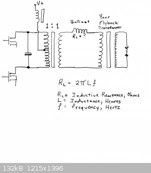
I think it is best to ensure that the reactance of the ballast that is reflected back to the primary is at least 10 times that of the primary
reactance. This should minimize the pulling effect that varying loads would have on operating frequency.
[Edited on 8-11-2014 by WGTR]
|
|
|
woelen
Super Administrator
Posts: 7977
Registered: 20-8-2005
Location: Netherlands
Member Is Offline
Mood: interested
|
|
Thanks for your suggestion of adding inductance on the primary side of the transformer. The 1 : 1 transformer as you suggest, can it be made with a
powdered iron toroidal core with 2x5 turns on one side and 10 turns on the other side?
|
|
|
WGTR
National Hazard
Posts: 971
Registered: 29-9-2013
Location: Online
Member Is Offline
Mood: Outline
|
|
In principle, yes.
When designing a transformer, usually you want the permeability of the core to be as high as practical. This minimizes losses associated with
magnetizing current and hysteresis. In this case, however, the primary of the transformer is part of a resonant circuit. The inductance and
capacitance needed in the tank circuit will be determined by the desired operating frequency and the load resistance.
There is more than one way to do this, but I'll attempt to explain this in a way that uses your iron powder torroidal core.
As a rough approximation, this is the design of the passive elements in the circuit:
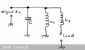
If L2>>L1, then L1 and C determine the parallel resonant frequency of the circuit. This is because the larger
L2 is compared to L1, the less effect L2 has on the circuit. I could show this mathematically if needed. In
effect, if the load is 0 ohms, then L1 and L2 are in parallel with each other.
Since the input is driven in push-pull, we have a center-tapped L1. L2 can be denoted as a balanced configuration of two equal
inductors.
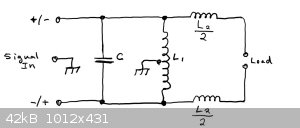
Expanding this out to an isolated configuration, L1 becomes the primary of a transformer, and L2 appears on the secondary side
of the circuit.
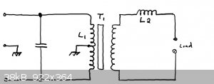
This is where we left off before. So the questions are if a iron powder torroidal core can be used as T1, and how many turns are needed.
First of all, it is necessary to ensure that the core does not saturate at the frequency and voltage that it is being driven at. Assuming that we
are driving the transformer with a square wave:
t = 1/(2f),
where t = time in seconds,
f = frequency in hertz
For a 100kHz square wave, this gives us t = 0.000,005 seconds.
Going further:
Wb = (V * t)/n,
where Wb = Webers,
V = average square wave driving voltage across the winding during interval 't'
t = time in seconds of applied voltage before flux reversal,
and n = the number of wire turns through the core.
At 13.8V, at 100kHz with 10 turns, this gives us Wb = 0.000,0069.
To calculate the flux density from this:
T = Wb/Amin,
where T = peak-to-peak flux density in Teslas
Wb = Webers (flux),
and Amin is the cross-sectional area of the core in square meters.
You can determine Amin by measuring the core with a pair of calipers, but oftentimes it is available directly on the manufacturer's data
sheet for the core.
Assuming Amin is 100mm^2:
Amin = 0.000,1m^2.
Therefore:
T = 0.000,0069/0.000,1 = 0.069 Teslas
This is the peak-to-peak flux density. Since the core is being driven alternately in both directions, the flux swing is centered about 0. Therefore
the peak flux density is 1/2 of the peak-to-peak number, i.e., 0.0345T in this case.
The peak flux density for a core that is being driven with a square wave AC signal would then be:
TPEAK =(V * t) / (n * Amin * 2)
If one wishes to input the frequency directly into the equation, you would get this:
TPEAK =V / (n * Amin * 4 * f)
It is this peak rating that is considered in manufacturer's datasheets.
Most iron powder cores will handle 0.5-1T before saturating, so we are well within the operating limits under these conditions. It's generally
better to keep the flux density low at high frequencies, due to hysteresis losses. These losses are especially high in iron powder cores.
The above example is for a primary of 20 turns, center-tapped, with 13.8V being applied to one-half the winding at a time.
The next issue is the inductance of this winding. It depends on the AL rating of the core, and this varies from one model to the next.
It is almost always specified from the manufacturer, if you know the origins of the core. If you don't, then you can put ten turns of wire through
the core and measure the inductance with a meter.
L = AL * n^2,
where L = inductance in Henries,
n = number of wire turns
and AL = inductance of one turn on a given core.
Note that doubling the number of turns causes the inductance to quadruple. Determining AL allows you to solve for the number of turns for
a desired inductance.
In the real world, you might end up with a core that requires 0.25 turns to give you the inductance that you want. This would be because the
permeability is too high. If it were even possible to make 0.25 turns, this would be undesirable, as it would cause the core to saturate easily. You
can buy cores according to their permeability, but if you pulled one out of an old power supply you might not be able to be so choosy.
In this case there is yet another option. L1 and T1 can be physically separate parts. As long as the inductance of T1 is high relative
to both L1 and L2, then it transfers power without appreciably affecting the tuning of C and L1. In other words,
L1 << L2 << T1; L1 has the lowest inductance, and T1 has the highest.

So in this case your torroidal transformer would have a 1:1 turns ratio, and have as many turns as you can fit onto it efficiently. As the number
of turns goes up, wire diameter decreases and length increases, increasing DC resistance in the winding. More turns decrease losses from hysteresis
and prevents core saturation. An iron powder torroidal core will run quite hot at high frequencies, with high flux density. Increasing the number
of turns decreases the losses associated with this.
There's some more that I'd like to add, but I'm running out of steam for the day. Iron powder should work, if the core permeability is high. It
would be better, however, to use ferrite instead of iron powder for T1. The material has much higher permeability, with lower losses.
What types of cores/materials do you have laying around?
[Edited on 8-14-2014 by WGTR]
|
|
|
12AX7
Post Harlot
Posts: 4803
Registered: 8-3-2005
Location: oscillating
Member Is Offline
Mood: informative
|
|
Yes, this circuit is a constant voltage output. So, unloaded, the supply current draw is generally low, and as you bring loads in (rusty nails,
hissing corona, etc...), current draw increases.
If the load increases much more than your circuit is comfortable with, excess supply current will be drawn. If your power source is not current
controlled, you'll have a problem, either from the power supply browning out (e.g., most flyback type power adapters, when heavily loaded, go into a
'pulse skip' mode which delivers very little average power into a very low to shorted load resistance), or your circuit burning up (I wouldn't
recommend running one from battery power, not without a current limiting resistor anyway).
An example of controlling one of these circuits might be,

This is a 10W, 300-2000V DC power supply I made for testing purposes. (I haven't finished the tester it's intended to power, so it's actually useless
right now...) The oscillator is recognizable at the bottom, and instead of a direct AC output, or an induction load, a high voltage secondary feeds a
full wave voltage doubler.
It's actually more like quasi-resonant, because I intended the transformer to have more leakage inductance (to allow the primary and secondary to
resonate with some freedom), but instead, it sort of goes into a 'high pitched whine' mode when shorted (namely, it runs at ~200kHz instead of the
normal ~60kHz). Whatever.
In any case, the important aspect is controllability. The output voltage is sensed with a high value resistor divider, buffered with an op-amp, then
compared to an adjustable reference voltage (0.19 to 2.08V) with a compensated error amplifier. The amplifier, in turn, drives a power amplifier
stage, which has a foldback current limit, 3A maximum, down to about 1A in a short circuit. Finally, a series inductor supplies the oscillator, to
provide "squishiness" necessary for commutation* and resonance.
*Commutation, as in, the instant in time when the transistors swap roles. In this case, the moment when one transistor turns on, followed by the
other turning off. This "push pull" circuit requires "shoot through" (both on for a short period), whereas most "bridge" circuits require "dead time"
(both off for a short period).
Pic:
http://seventransistorlabs.com/Images/HVPower2.jpg
Deadbug construction of course! The oscillator FETs aren't heatsinked, because they don't usually dissipate much power (the worst occurs under short
circuit conditions, when load current is high, supply voltage is low, and therefore, the transistors do not saturate fully but remain in the linear
range). The series pass transistor gets a nice big heatsink, because it can dissipate 10W easily (the overall efficiency of this circuit is fairly
poor, often under 50% IIRC).
An astute observer might note that a switching power supply would be more efficient than the linear pass transistor: that is true. I didn't do this,
to keep the circuit simple, and because efficiency doesn't matter for this purpose. I don't need to debug a buck converter as well as an oscillator,
plus their possible interactions (the oscillator expects clean DC).
(Funny, last time I posted in this thread, I gave general advice; a few months later and I've now built an example of my own, independently and for
unrelated purposes.)
Tim
Ed: eh, that pic's kind of wide
[Edited on 8-13-2014 by 12AX7]
|
|
|
IrC
International Hazard
Posts: 2710
Registered: 7-3-2005
Location: Eureka
Member Is Offline
Mood: Discovering
|
|
After rebuilding my very high voltage supplies as ZVS circuits and building a small but useful metal melter I got to thinking about the very large
power transfer into the load the ZVS circuit can produce. I replaced the oscillator section in an old 300 KV stun gun with a smaller version of the
ZVS design. Works too well and I shelved that for a later rainy day. Seems the spark gap burns up too quickly and the output multiplier section cannot
come close to handling the large increase in power. I had to reduce it and this is powered with a pair of 9 volt alkaline batteries. Played around
with circuit values and rewound my oscillator transformer (original was designed as a transistor oscillator with a pulse winding). The batteries are
not quite stiff enough even new for reliable starting. I mostly corrected this with higher primary impedance as well as going to 400 uH for the choke.
While it is low power compared with what we have all been toying with it still surpasses the original oscillator circuit the stun gun had.
If you have ever hacked a commercial stun gun you can picture what I mean. The spark gap is two short crossed wires, which now burn up too quickly
(start working erratically after a few bursts). Need to find a couple Tungsten wires for this. The multiplier is a plastic cylinder with internal
transformer and multiplier which goes out to the electrodes. I saw a few dim flashes inside so quit on this project for now. Appears it still
functions but obviously not designed for much power. Thinking if I can find an old defunct cattle prod to hack it may have a better version which can
take more power. This part would be fairly difficult to build and resin cast by hand but doable.
Having purchased 20 pounds of large pieces of Barium titanate (maybe surplus from early LRAD experiments?) I got the idea the ZVS circuit would be a
way to get serious sound wave power from. Tried with a piece of the ceramic (faces are Ag plated as terminals) and the factory board I dedicated for
my metal melter. Hand made two transformers to begin with after studying the prior post by WGTR. Works fairly well but needs some serious tailoring of
the circuit. It is clear that this approach perfected could produce an awesome and very dangerous level of sound power. As rough as it is right now it
clearly puts that hand sound phaser to shame that I studied in one of those 'evil genius' plans from Information Unlimited. Of course they are using a
few uS transducers which are not rated at much power. Something to experiment with at least.
"Science is the belief in the ignorance of the experts" Richard Feynman
|
|
|
WGTR
National Hazard
Posts: 971
Registered: 29-9-2013
Location: Online
Member Is Offline
Mood: Outline
|
|
I edited a few things in my previous post after looking at it again. I left off the correction factor that converts peak-to-peak ratings to peak
ones, considering that we're driving the inductors with an alternating voltage. This means that whatever inductor you designed with the equations
from before can handle twice the voltage before saturating than you thought they could.
With iron powder cores, however, you're limited more by core losses rather than saturation. If you ran an iron powder core up to saturation at
100kHz, it would be too hot to handle. Ferrite generally has much lower losses. In spite of this, one material isn't really better than the other
overall. It all comes down to application. Iron powder is more useful in a DC choke, because the flux swing is very limited (the purpose of a DC
choke after all), and iron can handle higher flux density than ferrite can, giving it a higher DC current-carrying capability than a similarly-sized
ferrite choke. Ferrite is better in transformer applications, where the flux swing is generally higher, but you have to be more careful not to
saturate it.
From the back of my fuzzy memory, I remember that many flyback transformers have a low self-resonant frequency, somewhere between 25-100kHz. It
varies from model to model. With the flyback driven directly from the driver as you did before, it helps set the resonant frequency of the driver.
With isolation from a ballast inductor, however, you have to be sure that the driver is supplying a frequency close to the self-resonant frequency of
the flyback. If not, the flyback won't give much or any output.
Also, I added/changed a few things for better clarity. The voltage specified in the equations is the average voltage during time interval
t. For a square wave, this is essentially equal to your supply voltage.
http://www.micrometals.com/material/pc_coreloss_txt.html
http://my.ece.ucsb.edu/York/Bobsclass/194/References/Isolate...
[Edited on 8-14-2014 by WGTR]
|
|
|
woelen
Super Administrator
Posts: 7977
Registered: 20-8-2005
Location: Netherlands
Member Is Offline
Mood: interested
|
|
WGTR, thanks for the effort you put in explaining these things to me. It is highly appreciated.
I can follow up your advice quite well I think. I ordered a few meters of 1 mm diameter enamelled copper wire, which will lead to very low DC
resistance and my toriodal core is quite large, so I can make quite a large number of turns around it. The enamelled wire hopefully will arrive this
weekend, I am eager to continue experimenting.
My available materials in this area are quite limited, I have more chemistry-related stuff, not so much in this area, but I use eBay to order
materials for low prices. Much comes from China with low prices and free shipping, but it takes weeks before the material arrives. For that reason I
ordered the enamelled wire in Europe, hoping that it arrives in just a few days.
|
|
|
WGTR
National Hazard
Posts: 971
Registered: 29-9-2013
Location: Online
Member Is Offline
Mood: Outline
|
|
You're very welcome woelen. I'm trying not be overly confusing about all this, but also trying not to be overly simple either. Such a simple thing
as an inductor is actually a complicated beast, and has driven many a university student to frustration. I have an entire (well-worn) binder full of
notes just on soft magnetics.
If you have trouble getting the driver going, let me know. It may be easier starting out just to add an equal (small) amount of inductance in series
with both halves of your primary coil (the one that is currently wrapped around the flyback). That would at least show you whether the circuit will
still oscillate and limit output loading at the same time. You want to keep the inductances low relative to the flyback primary inductance to start
out with, and then increase it for more load limiting. The circuit will work if the driver is just a simple push-pull driver, driven by an external
oscillator, but I don't know how a Mazilli driver will behave with the extra inductances in there.
Here's a useful nugget on wire design. Properly spec'd litz wire has an AC resistance that is the same as its DC resistance at a given set of
frequencies:
http://www.newenglandwire.com/~/media/Files/Litz_Theory.pdf
I'm going back to school this Fall, so in a couple of weeks I may be a little scarce around here. One can get old, or one can get old and educated.
But getting old is pretty much a given either way.
[Edited on 8-15-2014 by WGTR]
|
|
|
woelen
Super Administrator
Posts: 7977
Registered: 20-8-2005
Location: Netherlands
Member Is Offline
Mood: interested
|
|
The circuit I made is destroyed I replaced the fuse and it immediately is blown
out again, as soon as I switch on the power supply. Just doing the arcing apparently blew out one of the FETs. I do not understand why, I see videos
on Youtube with impressive arcs from 24 V or even 36 V power supplies. I just have 13.8 V. So, the experiment with the inductors in series with the
transformer is postponed, I first need to replace the transistor(s). I also need to understand why my circuit is destroyed, while others have
impressive results with their circuit.
[Edited on 21-8-14 by woelen]
|
|
|
WGTR
National Hazard
Posts: 971
Registered: 29-9-2013
Location: Online
Member Is Offline
Mood: Outline
|
|
When I started in electronics, about 25 years ago, it took me a year or two before I could get a transistor to actually amplify something. I firmly
believed that solid state technology was bogus, because it never worked for me. Come to find out, I was consistently hooking the devices up the wrong
way every single time. This was before Google, and I was learning things the hard way. I had an old analog voltmeter, a 1930's signal generator, and
a vacuum tube oscilloscope that would only work for 30 minutes at a time. Oh, yes, and no money.
Thankfully the situation is different now, but I understand the level of frustration that you're having.
|
|
|
IrC
International Hazard
Posts: 2710
Registered: 7-3-2005
Location: Eureka
Member Is Offline
Mood: Discovering
|
|
Been there, done that more than I care to admit. Often after 50 or more years working with electronics I still find myself in the been there done that
category. However I still refuse to admit it. Or did I in this post?
"Science is the belief in the ignorance of the experts" Richard Feynman
|
|
|
jpsmith123
National Hazard
Posts: 764
Registered: 24-6-2005
Member Is Offline
Mood: No Mood
|
|
I don't know if this could be relevant to your situation, but when I played around with the "Mazzilli driver" circuit, I noticed that it would
sometimes power up "the wrong way"; i.e., it would draw current, but it wouldn't oscillate. This would usually happen when I left the circuit
connected to my DC power supply and tried to power it up by turning on the DC power supply, rather than by manually connecting one of the leads to the
already-powered-up supply.
Apparently the applied voltage needs to ramp up fast for the "classical" Mazzilli circuit, and my power supply output didn't do it fast enough.
Quote: Originally posted by woelen  | The circuit I made is destroyed I replaced the fuse and it immediately is blown
out again, as soon as I switch on the power supply. Just doing the arcing apparently blew out one of the FETs. I do not understand why, I see videos
on Youtube with impressive arcs from 24 V or even 36 V power supplies. I just have 13.8 V. So, the experiment with the inductors in series with the
transformer is postponed, I first need to replace the transistor(s). I also need to understand why my circuit is destroyed, while others have
impressive results with their circuit.
[Edited on 21-8-14 by woelen] |
|
|
|
woelen
Super Administrator
Posts: 7977
Registered: 20-8-2005
Location: Netherlands
Member Is Offline
Mood: interested
|
|
I indeed powered up the power supply with the circuit already connected. Next time, I will try the other way around with a switch in the wires from
power supply to circuit.
Last Friday, a new set of PCBs arrived which allow me to build a ZVS driver with IRFP260s and I now also have good pwdered iron cores for choke
between power supply and the rest of the circuit. Everything is available now, so I hope to rebuild a new circuit next week.
The old PCB I will reuse as well, I have some IRF450N transistors as well, I could try these on the old PCB (they are smaller, but they should be good
enough for this purpose, they withstand voltages up to 500 V).
|
|
|
| Pages:
1
2
3
4
5 |
|


