| Pages:
1
2
3
4
..
9 |
Rosco Bodine
Banned
Posts: 6370
Registered: 29-9-2004
Member Is Offline
Mood: analytical
|
|
| Quote: | Originally posted by vulture
I've changed the thread title to PSU instead of PS, as the last abbreviation usually stands for PolyStyrene in chemistry... |
Laboratory Power Supply from Computer Power Supply
or perhaps
Laboratory Power Supply from ATX Power Supply
( written out in words would probably get the most
google search hits )
We invent new stuff here often enough , that when I google stuff to learn more , often what I find from search hits , turns out to be links here to my
own writings 
If only I had a better teacher  , ,
then I might learn something
[Edited on 22-1-2007 by Rosco Bodine]
|
|
|
Misanthropy
Hazard to Self

Posts: 69
Registered: 24-3-2005
Member Is Offline
Mood: Variable
|
|
Tried this the other night after I replaced the tempermental 100W thing I was hobbling along on with a 350W. No go. "When in doubt, check the wiring."
Yes, but it's still dead. Guess it was just time to go.
HOWEVER! I've salvaged a 250W AT PS from an old server at work! It has an externally cabled DPDT switch to an auxilliary 110VAC output as well &
-5VDC buss rated at 0.5W. 
No 3.3V of course, so no concurrent labwork/cell phone charging slated for the future on this one.
[Edited on 26-1-2007 by Misanthropy]
[Edited on 26-1-2007 by Misanthropy]
[Edited on 26-1-2007 by Misanthropy]
|
|
|
Hilski
Hazard to Others
Posts: 197
Registered: 13-9-2006
Member Is Offline
Mood: No Mood
|
|
| Quote: | | We invent new stuff here often enough , that when I google stuff to learn more , often what I find from search hits , turns out to be links here to my
own writings |
It's funny how no one else seems to write more about what one is interested in than one's self, eh?
\"They that can give up essential liberty
to obtain a little temporary safety
deserve neither liberty nor safety. \"
- Benjamin Franklin
|
|
|
Rosco Bodine
Banned
Posts: 6370
Registered: 29-9-2004
Member Is Offline
Mood: analytical
|
|
I wasn't joking ....it happens annoyingly often with
somewhat obscure topics that I have written a blurb or two about , then get curious and start searching .....
only to get two or three google hits to what I just posted , ......and not much else
Anyway , the quick and dirty ghetto adaptation of
the computer power supply to get some stepwise
approximately half volt drops is to use some high
current schottky rectifiers on heatsinks , in series
as if they were power resistors . Or get a heating
element of appropriate dissipation , and clip on a
tap along its length to get the drop needed , using
a jumper with an alligator clip . No regulation of
course .....but it will roughly throttle the current
if you need something simple as a quick solution and it
doesn't have to be precise or sophisticated .
|
|
|
Bromine
Harmless
Posts: 45
Registered: 7-9-2006
Location: Slovenija
Member Is Offline
Mood: good
|
|
Would it work if I conect two PSU from computer to get 24V? would it work or will i destroy both power supplys ? ( i have just basic electronic
knowledge)
|
|
|
dann2
International Hazard
Posts: 1523
Registered: 31-1-2007
Member Is Offline
Mood: No Mood
|
|
| Quote: | Originally posted by Bromine
Would it work if I conect two PSU from computer to get 24V? would it work or will i destroy both power supplys ? ( i have just basic electronic
knowledge) |
No, I do not think you could connect in series.
I asked a guy this and will come back to here.
You could connect in parallel using diodes to increase the current but you would probably need two identical supplies and even then the supplies might
not share the current equally between themselves if you ran the system at the new max current allowable.
Cheers,
Dann2
|
|
|
tumadre
Hazard to Others
Posts: 171
Registered: 10-5-2005
Member Is Offline
Mood: No Mood
|
|
-yes you can run PSUs in series-
To do so you must do one or both of the following:
remove the circuit board from the metal case, or,
cut the ground on the AC input.
(the negative/common output is connected to the AC ground through the case.)
most PSUs have 2-3 transformers rated >2KV RMS primary/secondary and one or two optical isolators in the feedback with a minimum of 400 v RMS
blocking ability
running in parallel:
first locate any SCRs that "crowbar" the output if it exceeds 3.4/5.1 or 12.9 volts.
next, locate the +/- pins for the two comparators on the 14 or 16 pin dip on the board.
-easiest method: destroy the feed back altogether and run it in a steady state of 46% duty cycle, and replace the 6/7.2/10 volt capacitors with
12/16/25 volt ones.
-don't even bother trying this on complex PSUs
|
|
|
Bromine
Harmless
Posts: 45
Registered: 7-9-2006
Location: Slovenija
Member Is Offline
Mood: good
|
|
What if I isolate metal cases so they dont tuch each other and conect normaly with AC. Then i conect +12VDC of one suply to -12VDC of second.
|
|
|
tumadre
Hazard to Others
Posts: 171
Registered: 10-5-2005
Member Is Offline
Mood: No Mood
|
|
just cut the ground wire
on the AC input, the "green wire"
[Edited on 8-4-2007 by tumadre]
|
|
|
Bromine
Harmless
Posts: 45
Registered: 7-9-2006
Location: Slovenija
Member Is Offline
Mood: good
|
|
ok thanks
|
|
|
12AX7
Post Harlot
Posts: 4803
Registered: 8-3-2005
Location: oscillating
Member Is Offline
Mood: informative
|
|
Connect +12V to GND of the other, NOT -12V. The -12V supply will only produce maybe an ampere, if that. Read the label.
Tim
|
|
|
tupence_hapeny
Hazard to Others
Posts: 131
Registered: 25-3-2007
Member Is Offline
Mood: continuing respiration (touch wood)
|
|
For the australian members, please just check out Tandy(some)/DSE(all), they sell Lab PSU's for around $150-200 - they also sell a lot of other handy
gadgets (IR Temp Guns - very useful for MW chemistry = ~ $70, thermocouples, some nichrome wire and electrical connectors, also look at the PC fans,
magnets, connectors, dimmer switch kits & aluminium boxes to put it all in). Shit, with what they have a DIY heat-mantle with stirrer, and with
LCD heat display & maybe even stirrer speed should be possible.
As to lab power supplies but, buy it - way simpler & easier and less bloody dangerous - in OZ you are looking at 240V in, not something I like
taking chances on - if you want to tinker do so where the voltage is considerably less (particularly if the end application may be used near solvents,
etc.).
tup
We are all the sum of our experiences, and our reactions to the same
|
|
|
Rosco Bodine
Banned
Posts: 6370
Registered: 29-9-2004
Member Is Offline
Mood: analytical
|
|
| Quote: | Originally posted by tupence_hapeny
For the australian members, please just check out Tandy(some)/DSE(all), they sell Lab PSU's for around $150-200 - |
And what ampere rating do you get for that price ?
Not all lab supplies have enough muscle for any serious
electrolysis production rates .
| Quote: |
they also sell a lot of other handy gadgets (IR Temp Guns - very useful for MW chemistry = ~ $70, thermocouples, some nichrome wire and electrical
connectors, also look at the PC fans, magnets, connectors, dimmer switch kits & aluminium boxes to put it all in). Shit, with what they have a DIY
heat-mantle with stirrer, and with LCD heat display & maybe even stirrer speed should be possible. |
Making a good stirring mantle , or a stirring anything really ,
requires some very carefully selected and matched components and is not as easy as it may seem , especially for the low speed performance it is
actually very difficult to
find the right combination .
| Quote: |
As to lab power supplies but, buy it - way simpler & easier and less bloody dangerous - in OZ you are looking at 240V in, not something I like
taking chances on - if you want to tinker do so where the voltage is considerably less (particularly if the end application may be used near solvents,
etc.).
tup |
Yes , if you are not comfortable with building experimental electrical equipment , then absolutely do buy a commercial unit if you have the money or
find a bargain . I have no particular prejudice against any quality commercially built lab power supplies , and in fact I own a couple of them which
were scavenged at auctions of surplus military equipment . All I was trying to do in developing this as yet untested and therefore entirely
theoretical and experimental design is to illustrate a possible " converter
box " which might be used to provide an "off label use " for a computer power supply . When I have time myself , I will probably get around to
building and testing it simply out of curiosity , but certainly not out of necessity .
I am lucky enough to to already have a mil spec 50A continuous duty laboratory power supply which covers the 1.5 to 7 volts range . It is a linear
supply which weighs about fifty pounds , has a transformer core 6"X4"X 2 1/4" , and *twelve* 12 parallel TO-3 output transistors mounted on a square
foot of 3/16" solid copper plate bristling with 2" convoluted cooling fins , and a C-frame motor with a 5" fan blowing air across the array , three
filter capacitors the size of pint jars , two circuit boards about the size of cigar boxes babysitting the whole shebang , and of course mechanical
thermal and short circuit and overcurrent breakers redundant to the electronics ....about a $2,000 power supply for which I paid about one hundredth
that figure ....not bad either since it is in mint condition and it cost me less
than what would cost a computer power supply . But I am a pretty good scrounger and was lucky to find such a rare deal .
Now you can probably find a new switcher of similar capacity
for something over a thousand dollars .
And when these figures sink in ....then maybe you see why
for many experimenters who may have more technical saavy
than money , a converter that can be built to do the same job
at a tenth the cost , might be worth a shot .
[Edited on 25-5-2007 by Rosco Bodine]
|
|
|
dann2
International Hazard
Posts: 1523
Registered: 31-1-2007
Member Is Offline
Mood: No Mood
|
|
Hello,
Link to a project converting a computer PSU here:
http://www.fieldlines.com/story/2007/10/18/16953/116
May be useful, I dunno.
Dann2
|
|
|
Twospoons
International Hazard
Posts: 1280
Registered: 26-7-2004
Location: Middle Earth
Member Is Offline
Mood: A trace of hope...
|
|
It pays to keep an eye on the auction sites (like ebay). I just scored a 0-50V, 0-60A Hewlett Packard lab supply for NZ$ 300. These sorts of thing
pop up from time to time, being sold by folks who have no idea of their worth.
FYI Rosco (just 'cos I thought it might interest you ) the HP supply uses an SCR
phase-control pre-regulator, followed by a stepdown transformer, then a linear post-regulator. Weighs about 45kg, since the tranny is still a 50Hz
tranny, transferring 2.5kW.
Helicopter: "helico" -> spiral, "pter" -> with wings
|
|
|
Xenoid
National Hazard
Posts: 775
Registered: 14-6-2007
Location: Springs Junction, New Zealand
Member Is Offline
Mood: Comfortably Numb
|
|
| Quote: | Originally posted by Twospoons
I just scored a 0-50V, 0-60A Hewlett Packard lab supply for NZ$ 300. |
Ahhh.. Twospoons, that was you was it! I had my eye on a constant current 60Amp HP supply on "Trade Me" but ummed and aaahed a little too long! I see
they still have a 100Amp CC unit (1KW) available, ideal for electrolysis work! The freight is a bit of a killer though!
Regards, Xenoid
|
|
|
Rosco Bodine
Banned
Posts: 6370
Registered: 29-9-2004
Member Is Offline
Mood: analytical
|
|
| Quote: | Originally posted by Twospoons
FYI Rosco (just 'cos I thought it might interest you ) the HP supply uses an SCR
phase-control pre-regulator, followed by a stepdown transformer, then a linear post-regulator. Weighs about 45kg, since the tranny is still a 50Hz
tranny, transferring 2.5kW. |
Yeah for the nuts and bolts approach to a high efficiency linear I was first looking at using a variac to control the input to the primary on a large
fixed transformer with rectification and huge capacitor filtering to follow , and then a linear post regulator ganged with the variac ....to keep the
dissipation to a minimum for the linear regulator which would just clean up the last bit of ripple . Same idea with the SCR but probably a bit
spikier using the SCR pre-reg instead of using a variac to keep the sine wave intact .
For about a month Der Alte and I were discussing in U2U's my proposed idea for a post regulator for an ATX supply
using two IRFP3703's as series elements in a negative regulator scheme . I modeled that VCCS module using LT Spice and never was satisfied with even
the C-Load LT op amps capability to drive that capacitve load without peaking problems showing up in the spice simulation . I then used an active low
pass filter as a buffer and an emitter follower
NPN 2222 as the mosfet driver , limiting the gate drive voltage in the 1.5 to 6 volt range for linear region operation and that works . All the DC
analysis tracks perfectly with what I had figured , and it checks out fine , but the small signal AC analysis that LT Spice is generating is pure
fiction ......showing impossible results , inverted signals and so much garbage that it is about like I had predicted and expected , the spice
simulator isn't sophisticated enough to give it a fair rendering . No escaping actually building the circuit for testing and using a real life
oscilloscope on this one .
Multisim might track it better with a large signal AC analysis , but LT Spice is full of shit on small signal AC analysis , simply by looking at the
voltage scale and knowing that there isn't enough threshold on a mosfet to have any output , while LT Spice happily bullshits its way along with those
small signal AC analysis figures .....like a mosfets gate threshold is at zero instead of 2-3 volts where it is in the real world .
Probes of node readings show voltage and power inversions
and differential voltages when you have the reference set for ground .....so the sim has gone nuts trying to track what it can't .
The spice models for linear region operation of mosfets are pure crap too so that may be part of the simulation problem .
Another simulation anomaly you'll see is in phase opposite voltages on op amps inputs in a closed loop which is another impossibility . What I am
seeing with spice sims is it does pretty good with simple known templated stuff but totally lapses and loses it with AC analysis of complex circuits
, and spits out "would you believe this?" kinds of results .....while I sit there saying no , not hardly
Anyway , what I have been contemplating doing is a known and published configuration with regards to the VCCS ...so I am not just way out in left
field , it can be done , though the devil seems to be in the details
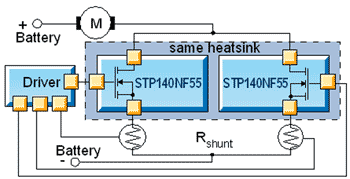
image from negative regulator linear application for power mosfets writeup on the following page
http://www.st.com/stonline/products/families/transistors/pow...
Hehehe .... Know 12AX7 has got to love this ......
okay Tim come get your spanking
[Edited on 19-10-2007 by Rosco Bodine]
|
|
|
Rosco Bodine
Banned
Posts: 6370
Registered: 29-9-2004
Member Is Offline
Mood: analytical
|
|
5 volt @ 50A $12.79 free FedEx ground
I ran across this ATX deal on pricewatch and thought I should share it
http://www.pcboost.com/store/viewitem.asp?idproduct=13811
This is the sort of deal which makes the idea
so appealing of adapting an ATX supply for use in electrolysis , as they are the cheapest efficient source of usable current level anyone is going to
find .
|
|
|
DerAlte
National Hazard
Posts: 779
Registered: 14-5-2007
Location: Erehwon
Member Is Offline
Mood: Disgusted
|
|
There seems to be no excuse anymore for using that old battery charger!
With regard to electrolysis, I would be interested to hear what the electrolysis community here would consider the most important thing needed for a
PS.
In some cases it seems that a strictly controlled voltage would be beneficial - to separate ions having differing SEP, e.g. In other cases, a
controlled current might make more sense, allowing the cell to attain its natural potential; a case in point might be chlorate production, where the
current density determines the product to some extent, and some of the energy is used to heat the electrolyte to encourage the side reaction of
hypochlorite disproportionation, a purely chemical process. I know Rosco is trying to produce a flexible beast with both options .
@Rosco, had a look at your alternate NMOSFET choice. Much more Kosher, from the characteristics POV. I see you have come around to my view of SIMS!
They have a place, but are only as good as the device models used. One has no idea what they are. They can be trusted for things like filters and
passive circuits and even active opamp filters like the Sallen-Key type, provided you are far enough away from the unity gain frequency of the opamp.
@Rosco - I'll send a short U2U soon regarding something that occurred to me on reading this thread.
Regards,
Der Alte
|
|
|
Rosco Bodine
Banned
Posts: 6370
Registered: 29-9-2004
Member Is Offline
Mood: analytical
|
|
| Quote: | Originally posted by DerAlte
There seems to be no excuse anymore for using that old battery charger! |
YGTFR! Even without any fancy regulator , you could probably improvise a power
resistor from a welding carbon , and a sliding clamp to roughly throttle the current from an ATX supply , or use a heating element as a power resistor
and an alligator clip , like some have already done .
| Quote: |
@Rosco, had a look at your alternate NMOSFET choice. Much more Kosher, from the characteristics POV. I see you have come around to my view of SIMS!
They have a place, but are only as good as the device models used. One has no idea what they are. They can be trusted for things like filters and
passive circuits and even active opamp filters like the Sallen-Key type, provided you are far enough away from the unity gain frequency of the opamp.
Regards,
Der Alte |
Yeah those folks at STMicroelectronics are talking my language on a couple of finer points regarding power mosfets . Especially with regards to
ruggedness concerns , like putting a zener network bracketing the gate to provide ESD and inductive voltage spike protection , which would seem to be
a no brainer for *all* mosfets to protect the fragile oxide layer from puncture . Yet so many manufacturers cut a corner there and just have one
solitary zener which provides only a half-assed device protection in the actual cruel world power environment where transients
and static are there all the time . I never saw a mosfet
wearing its own antistatic wrist strap for the post assembly board residing time when its worries are a whole lot bigger than your body static and
soldering iron during assembly
The folks at STM seem to understand that no brainer also
in having implemented their "SafeFET" architecture .

http://www.st.com/stonline/products/families/transistors/pow...
I am thinking that since the STM folks seem to have dedicated some development time and interest in linear power applications for mosfets , they may
have worked out the models and modeling software for linear mosfet applications which will generate some intelligent simulations . Maybe I'll drop
'em an e-mail and see if they can be helpful .
[Edited on 21-10-2007 by Rosco Bodine]
|
|
|
12AX7
Post Harlot
Posts: 4803
Registered: 8-3-2005
Location: oscillating
Member Is Offline
Mood: informative
|
|
Eww, why in God's green Earth would you want conduction from gate to drain!?
Tim
|
|
|
Rosco Bodine
Banned
Posts: 6370
Registered: 29-9-2004
Member Is Offline
Mood: analytical
|
|
There isn't any conduction there so long as the gate voltage is within the window values allowable by the zener voltages , which will be the case so
long as gate drive voltage is normal polarity and allowable level .
The zener bracketing is invisible to any normal gate drive signal level voltage and normal polarity WRT drain or source .
But the zener from gate to drain will protect the gate oxide layer against the reverse breakdown potential possible to do the same sort of damage when
voltage on the gate is higher than the drain as is provided in the more limited protection of a single zener from gate to source , which clamps normal
polarity gate overvoltage .
The zener bracketing does a similar thing as what a varistor would accomplish in the way of clamping abnormal gate voltage without regard to polarity
of the offending overvoltage . This will shunt any destructive gate voltage level of either forward or reverse polarity around the device .
On switching an inductive load this would be a very wise precaution .
Actually I have seen this same scheme used on the high impedance inputs of CMOS op amps which are unusually
vulnerable to being ruined by stray charges , and it is probably used to harden mil spec equipment against EMP as well .
It makes the mosfet bulletproof to stray or induced abnormal voltages . I see on the applications list they say this device is used in automotive
anti-lock braking solenoid pulsing applications ...which makes sense .
[Edited on 21-10-2007 by Rosco Bodine]
|
|
|
12AX7
Post Harlot
Posts: 4803
Registered: 8-3-2005
Location: oscillating
Member Is Offline
Mood: informative
|
|
| Quote: | | Actually I have seen this same scheme used on the high impedance inputs of CMOS |
No, YOU HAVEN'T.
ICs are protected by clamp diodes which direct charge into the power supply rails. There is no gate-drain connection. Moreover, the
rated power supply voltage on CMOS chips, by their very nature cannot cause gate breakdown, so a drain-gate zener would be useless.
If you connect a zener from drain to gate and supply breakdown voltage to that drain, the gate's voltage will zoom up towards the drain and BOOM, hole
in the gate. You die, you lose, do not pass go, do not collect $200, but do please collect a large pile of exploded silicon, at your expense.
Every single switching MOSFET I have ever seen is rated for avalanche, so a zener protecting the drain is not only foolhardy and dangerous, but
superfluous as well!
The argument ends here Rosco. Accept truth.
Tim
[Edited on 10-21-2007 by 12AX7]
|
|
|
Rosco Bodine
Banned
Posts: 6370
Registered: 29-9-2004
Member Is Offline
Mood: analytical
|
|
You aren't seeing the forest for the trees .
It is evident you aren't accounting for the fact that the usual gate to source zener would provide protection in the very scenario where you say the
oxide would be holed by a drain voltage sufficent to cause avalanche .
What you are saying about avalanche operation of a mosfet is irrelevant to gate protection . You are describing a latchup scenario which doesn't
involve gate destruction . Avalanche is recoverable if it is transient or limited ....it is gate destruction that is permanent .
For op-amps stray ESD and inductive voltages can be way above and beyond the rails with their own superimposed potentials that may even be quite
opposite polarity to what the normal power supply arrangement is providing . The oxide layer between the metal gate and the mosfet body NPN structure
is vulnerable to having that dielectric punctured , regardless of the polarity of the metal gate with respect to the body .
I have seen clamp diodes used different ways including to limiting the differential voltage between inputs , back to back zeners between the inputs
and rails , and zeners combined with ordinary diodes too , and sometimes combinations of such diode arrangements across op amp inputs . But I'm not
going to dig up every protection strategy example for protected CMOS inputs I can find just to prove it to you .
|
|
|
Rosco Bodine
Banned
Posts: 6370
Registered: 29-9-2004
Member Is Offline
Mood: analytical
|
|
Well lookee here what I found
Here's an STM scheme for infinite speed control of an automotive heater and air blower , which looks a whole lot like the negative regulator scheme
which I have been proposing , not exactly , but very closely similar .
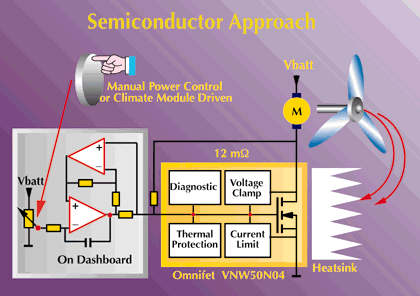
from the following page
http://www.st.com/stonline/press/magazine/prodnews/2ndedi00/...
The "On Dashboard Module" part of this regulator scheme doesn't seem to be fully disclosed in detail , and may be proprietary ....which goes precisely
to what I was saying earlier about the devil being in the details
But the general idea of what I am trying to do is possible ,
as can be seen here .
[Edited on 22-10-2007 by Rosco Bodine]
|
|
|
| Pages:
1
2
3
4
..
9 |


