| Pages:
1
..
6
7
8
9 |
12AX7
Post Harlot

Posts: 4803
Registered: 8-3-2005
Location: oscillating
Member Is Offline
Mood: informative
|
|
| Quote: | Originally posted by Rosco Bodine
The parts expense
adds up fast as the quality of the thing is increased.
|
Only if you are HP. 
We ain't HP, and we don't need their kind of specs, so we can make do quite well here.
For IC1, try LM837 or MC33079. I don't think an LM324 is really suitable here, but if you're feeling really cheap, you can. You'll need more
compensation somewhere, which means the whole thing runs slower, which means more ripple and slower response time. Probably not an issue, but in
principle you might as well build it better right?
And for IC2, a TL071 or LF411 is fine. If you do chose LM324 for IC1, you might as well use a (cough) LM741 here.
Tim
[Edited on 10-24-2008 by 12AX7]
|
|
|
saki2fifty
Harmless
Posts: 3
Registered: 23-10-2008
Member Is Offline
Mood: Great!
|
|

On lunch break at work...
Just laying out the parts on a perf board app in my spare time... but question regarding your "module", which Mosfet did you have in mind as well as
alternatives to use? Also, you mentioned to place a cap on each op-amps output to -in... just want to make sure you were saying across the out / in
of the actual IC and not the "module". What size cap?
Roscoe, can we possibly get the cad file uploaded so as not to redraw the shematic. No biggie, shouldn't be too hard. I did locate the sofware you
were talking about...
Thx,
Michael
---
Michael
Houston, Tx.
|
|
|
Rosco Bodine
Banned
Posts: 6370
Registered: 29-9-2004
Member Is Offline
Mood: analytical
|
|
Yeah , here is the cct file . I'll try to attach it here and if that doesn't work I'll put it on the forum FTP . I think I found the
cct file where I started to rescale it , but didn't do anything further on it. I can also upload the DesignWorks program
to the FTP if it is needed . It is really an easy to use entry level drawing program which is why I used it...but unfortunately it doesn't seem to
export the drawing to more capable SPICE higher end programs like MultiSim ect.
I still don't fully trust the sims on this thing anyway, even on the output module alone.
Attachment: Converter for 550W ATX Power Supply to 50A Laboratory Power Supply.cct (46kB)
This file has been downloaded 989 times
|
|
|
Rosco Bodine
Banned
Posts: 6370
Registered: 29-9-2004
Member Is Offline
Mood: analytical
|
|
And here is the one where I was rescaling the drawing to
provide room to fit in the larger LTC1152 output modules.
Also I ran across an ATX PS that seems to have some "heft"
to it and decent reviews , at a decent price . It might be good for this sort of project or just a good backup PS for
the usual labeled use.
http://www.newegg.com/Product/Product.aspx?Item=N82E16817101...
I chuckled when reading the reviews mentioning having to cut a hole in the top of the case for the computer to match the fan on the PS  ....like Duh it would help if the genius ....like Duh it would help if the genius
installing the PS would not install it upside down  ..... .....
You would think that the fourth screw hole not matching up
would be a clue there that the damn thing was flipped
Can just hear the guys old lady at night ...
saying "wrong hole" hehehe 
Press any key .....but I looked everywhere and my keyboard doesn't have an "any" key
[Edited on 27-10-2008 by Rosco Bodine]
Attachment: #2 Copy of Converter for 550W ATX Power Supply to 50A Laboratory Power Supply.cct (46kB)
This file has been downloaded 1073 times
|
|
|
Sedit
International Hazard
Posts: 1939
Registered: 23-11-2008
Member Is Offline
Mood: Manic Expressive
|
|
I was woundering if anyone here could help me out with a little something.
I just took the power supply out of my computer... Then put it back in so I could type this message j/k
Anyhoo I have not read this whole threed as of yet because it appeared to be turning into a willy waving contest but reading the page that Org/ posted
gave me a rough Idea of what I need to do yet I am still having issues. My main question would be, is it normal that the power supply kicks off after
a few seconds? I don't think its a bad supply as the computer stayed running right before I ripped it out but I feel that the load across one of the
red and black is not enough because for now until I find/buy a suitable resistor I have a couple of small fans and a large coil of wire place across
it.
Doing this, where as it appears to helped some, still does not stop it from kicking off after 20 seconds or less of run time.
The main thing that is throwing me off is after the power is completely cut the PSU fan comes back on in pulses so it appears a capacitor is
resonating with something but Im unsure how the safety mechanics of the supply work in preventing operation without a large enough load.
Any suggestions?
And is this normal?
Knowledge is useless to useless people...
"I see a lot of patterns in our behavior as a nation that parallel a lot of other historical processes. The fall of Rome, the fall of Germany — the
fall of the ruling country, the people who think they can do whatever they want without anybody else's consent. I've seen this story
before."~Maynard James Keenan
|
|
|
12AX7
Post Harlot
Posts: 4803
Registered: 8-3-2005
Location: oscillating
Member Is Offline
Mood: informative
|
|
Sounds like overload to me.
|
|
|
Sedit
International Hazard
Posts: 1939
Registered: 23-11-2008
Member Is Offline
Mood: Manic Expressive
|
|
Thats kind of what I was thinking at first but I appeared to have magicly fixed my problem by placing the fan I was using as a small load across the
blue and ground and feeding the cell with the red and ground. Since im not a big fan of magic in my chemistry im going to run more test on the various
output wire tommorow with a multimeter and try to get a better idea of whats going on and if there is a spike or something when the other arrangment
kicks out.
All and all though even though im learning it as I go it looks as though its going to shape up into a nice little setup considering I would like to be
able to use the terminals im using for the load to power an overhead stirrer for the cell.
[edit]
Overload it is I believe. There must be some safety protection inside of the unit that forces shutdown in the case of an overload. I have to have a
load of some sorts placed across either of the two main wires beit red/ground or blue/ground to prevent this. The Electrochemical cell is acting as
one load while the cooling fan from another powersupply is acting as a second load across the other terminals.
I found this which may be of some interest to folks here and I apologise if its been posted already.
http://www.wikihow.com/Convert-a-Computer-ATX-Power-Supply-t...
[Edited on 23-7-2009 by Sedit]
Knowledge is useless to useless people...
"I see a lot of patterns in our behavior as a nation that parallel a lot of other historical processes. The fall of Rome, the fall of Germany — the
fall of the ruling country, the people who think they can do whatever they want without anybody else's consent. I've seen this story
before."~Maynard James Keenan
|
|
|
Sedit
International Hazard
Posts: 1939
Registered: 23-11-2008
Member Is Offline
Mood: Manic Expressive
|
|
Well I once again am having problems with the PSU because even with the fan across it kicks off after about 10-15 minutes of run time.
Is this normal when one has an improper load or would I be best to try to use a different powersupply from another computer?
Im having alot of problems diagnosing the cause of the shutdown because my multimeters have on the best one a 15 amp fuse and Im not prepared to
destroy my multimeter in order to make this thing.
All I have noticed is that when it gets to about 3v after a second or so is when it kicks off but this tells me next to nothing about whats really
going on.
Knowledge is useless to useless people...
"I see a lot of patterns in our behavior as a nation that parallel a lot of other historical processes. The fall of Rome, the fall of Germany — the
fall of the ruling country, the people who think they can do whatever they want without anybody else's consent. I've seen this story
before."~Maynard James Keenan
|
|
|
12AX7
Post Harlot
Posts: 4803
Registered: 8-3-2005
Location: oscillating
Member Is Offline
Mood: informative
|
|
When I tried using an ATX supply on my cell, it appeared to work for a little while, but failed while I was away, probably as the cell heated up and
current consumption rose from 20A towards 50A.
Shutdown is probably current controlled. These supplies usually have a current transformer monitoring what the transistors are switching. Too much
for too long and it kicks off to protect itself. Much more and the transistors themselves cook, or some other part, like the filter coils or diodes
(especially if just one output is heavily loaded).
Tim
|
|
|
Sedit
International Hazard
Posts: 1939
Registered: 23-11-2008
Member Is Offline
Mood: Manic Expressive
|
|
Thats what I was afraid to here because it seems as though im having the same issue. Its very frustrating because I read all these writeups and stuff
telling how to do it, follow it to a Tee, and have it not work time and time again. Not only that but I think I killed my best supply. I have been
tinkering with this for two or three days now with little to no improvement on its performance.
The wires I have are such,
Blue: +12v 8A
Red: + 5v 23A
Orange: - 5v .5A
Yellow: +12v .5A
Black: Grn
White: ??POK??
Thats what the white is labled and I don't know what this means so im doing nothing with it at the moment.
I have a 10ohm resistor placed across Red/Grn and Blue/Grn placed across the cell. This has so far provided the longest on times I have been able to
get. Placing the Resistor across Blue/grn and using Red/Grn for the cell appears to work better but the resistor gets very hot very fast doing it this
way.
Im under the same impression as you are that after a while to many amps start flowing and kicking on a safe gaurd kill switch. How would I go about
preventing this? Perhaps a dimmer switch across the AC in to slow the power in the first place?
Its just frustating because I have heard of people using these for cells before yet as it stands now it does not seem possible.
Knowledge is useless to useless people...
"I see a lot of patterns in our behavior as a nation that parallel a lot of other historical processes. The fall of Rome, the fall of Germany — the
fall of the ruling country, the people who think they can do whatever they want without anybody else's consent. I've seen this story
before."~Maynard James Keenan
|
|
|
The_Davster
A pnictogen
Posts: 2861
Registered: 18-11-2003
Member Is Offline
Mood: .
|
|
This link http://web2.murraystate.edu/andy.batts/ps/powersupply.htm from the original post tells exactly waht needs to be hooked up to make a viable PSU.
It has worked for me without fail on numerous computer power supplies.
|
|
|
12AX7
Post Harlot
Posts: 4803
Registered: 8-3-2005
Location: oscillating
Member Is Offline
Mood: informative
|
|
Quote: Originally posted by Sedit  |
The wires I have are such,
Blue: +12v 8A
Red: + 5v 23A
Orange: - 5v .5A
Yellow: +12v .5A
Black: Grn
White: ??POK??
Thats what the white is labled and I don't know what this means so im doing nothing with it at the moment. |
Surely you have that backwards? Yellow is pretty standard as +12V, moderate amps. And surely you meant -12V 0.5A?
| Quote: | | I have a 10ohm resistor placed across Red/Grn and Blue/Grn placed across the cell. This has so far provided the longest on times I have been able to
get. Placing the Resistor across Blue/grn and using Red/Grn for the cell appears to work better but the resistor gets very hot very fast doing it this
way. |
If blue is indeed delivering 12V (of whichever polarity), you would need a 14.4W resistor for that, so yes, it should get hot.
| Quote: |
Im under the same impression as you are that after a while to many amps start flowing and kicking on a safe gaurd kill switch. How would I go about
preventing this? Perhaps a dimmer switch across the AC in to slow the power in the first place? |
EWWW! Dimmer switch + electronics = let out all the magic smoke!
And besides, reducing the input *increases* the current drawn, since it's a regulating supply after all. But that's still beside the point.
Anyway, just use less electrode, or more distance between them. You might preheat the cell so it doesn't come up to operating temperature when you're
away.
Tim
|
|
|
Sedit
International Hazard
Posts: 1939
Registered: 23-11-2008
Member Is Offline
Mood: Manic Expressive
|
|
Thats what im following along with some other writeups that state the same thing yet I am not having success at all. Im afraid its not that simple as
there must be some other variable that that writeup is not accounting for such as the current that the cell itself is drawing.
POK(white) is the only wire I don't know what to do with. The on switch in mine is also different then stated in the link provided as its nothing more
then a heavy duty white/black wires placed across the AC plug that must be jumpered in order to achieve startup.
As it stands now following everything to that writeup I can only achieve 10 seconds or less of power before it goes into shutdown.
[edit]
Yes I ment -12v sorry about that, No Im positive that the yellow is the -12.
| Quote: | EWWW! Dimmer switch + electronics = let out all the magic smoke!
And besides, reducing the input *increases* the current drawn, since it's a regulating supply after all. But that's still beside the point.
Anyway, just use less electrode, or more distance between them. You might preheat the cell so it doesn't come up to operating temperature when you're
away.
Tim |
Yes I noticed it shuts down quicker when placed across the AC input.
[edit#2]
Ahhhh yess indeed Tim. After increasing the distance of the plates it appears to be working fine so cross my fingers and pray that it stays that way
and life will be good
[Edited on 25-7-2009 by Sedit]
Knowledge is useless to useless people...
"I see a lot of patterns in our behavior as a nation that parallel a lot of other historical processes. The fall of Rome, the fall of Germany — the
fall of the ruling country, the people who think they can do whatever they want without anybody else's consent. I've seen this story
before."~Maynard James Keenan
|
|
|
watson.fawkes
International Hazard
Posts: 2793
Registered: 16-8-2008
Member Is Offline
Mood: No Mood
|
|
Not that this is immediately relevant, but computer PSU's have a rather restricted operating envelope because the loads they serve are rather
well-behaved, as loads go. While the power draw from a computer isn't quite constant, it's still in a small window, almost purely resistive (power
factor very close to 1), doesn't suddenly change by an order of magnitude, etc. There's always a minimum load (the CPU board), the maximum load is
constrained by the number of devices in the box (barring failures), and what motors are present have minuscule startup torque. This is not at all the
kind of load profile that a lab PSU sees: no load, shorted load, sudden changes, and generally all sorts of crap. So while you can press a computer
PSU into service as a lab PSU, you've got to be careful with it.
I've half-thought about making a little adapter box that would add some of the basic protections needed to perform the computer -> lab conversion.
It would have an ATX connector as an input, and provide minimum current draw and overvoltage protection in either crowbar (react by turning off) or
current limiting (react by dropping voltage) mode. Crowbar is really easy to implement on an ATX supply because of the /PS_ON pin that allows software
shutdown of the power. @12AX7: If you're considering alternate PSU projects, think about something like this rather than a full-blown supply.
Indeed, there may be some trickery available to coax more than 5.0 V out of the +5 V (nominal) supply by putting a programmable voltage reference
across the sense return, but that's not broken out on the ATX connector and may not even by implemented in some PSU's. That, however, is not a product
opportunity but a hacking project.
|
|
|
The_Davster
A pnictogen
Posts: 2861
Registered: 18-11-2003
Member Is Offline
Mood: .
|
|
Sedit: brand of power supply you are playing with? some have odd color coding. Best is to get a motherboard ATX connector pinout, and connect what
is necessary. ie red/black via 10W 10ohm, and appropriate wire to ground via a switch for power on.
Exactly what do you have hooked up to what currently?
I tend to think something is wrong with yours(or simpler and too much current is being pulled), I have abused at least 2 ATX power supplies, pulling
at least 50% more amps than rated for days. The only failure is when much too much current is pulled and it turns off, easily fixed by a flicking off
and on again. Well I also have had a failure when I pulled too many amps and burned all the insulation off the 5V red lines...
could this be relavent to your supply? from your link above
"# If you DO have a sense wire for the 3.3v. , connecting the the 3.3 v. part of the supply, using the 3.3v. voltage as a buck voltage against, say
the 12v. to get 8.7v. will not work. You will see 8.7 v. with a volt meter but when you load that 8.7v. circuit the power supply may go into
protective mode and shut the whole supply down.
# You can add a 3.3 volt output (such as to power 3V battery-powered devices) to the supply by hooking the orange wires to a post (making sure the
brown wire remains connected to an orange wire) but beware that they share the same power output as the 5 volt, and thus you must not exceed the total
power output of these two outputs."
[Edited on 26-7-09 by The_Davster]
|
|
|
Sedit
International Hazard
Posts: 1939
Registered: 23-11-2008
Member Is Offline
Mood: Manic Expressive
|
|
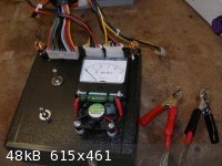
Very nice little setup you have there Davster I have high hopes of getting mine to look that nice soon enough.
I will get all the information tommorow on the brand of powersupply but after doing what Tim suggested of moving the electrodes in the cell itself
further apart and playing around with how much of the electrodes are in the solution I managed to get it working perfectly(or so it appears for
now). I would have more then likely been able to come to this conclusion myself
if I was able to use my multimeter here but the 10amp fuse was highly limiting in what I could diagnose.
I have some pictures I will post tommorow as well so you can see for your self before I start locking everything in its place and drilling out for the
grommets. Basicly I just have a 10ohm resister across the red and ground strapped to the fan pretty much how yours is setup there to keep it cool and
am also currently running the cell off of red and ground as well. All other wires except the on switch are just loose at the moment and not doing
anything one way or another.
I admit im not the greatest with electrical theory and stuff but I can still manage to make quite a few things using it without electrocuting
myself...badly anyway(except that one time im lucky to have lived thru)
Knowledge is useless to useless people...
"I see a lot of patterns in our behavior as a nation that parallel a lot of other historical processes. The fall of Rome, the fall of Germany — the
fall of the ruling country, the people who think they can do whatever they want without anybody else's consent. I've seen this story
before."~Maynard James Keenan
|
|
|
dann2
International Hazard
Posts: 1523
Registered: 31-1-2007
Member Is Offline
Mood: No Mood
|
|
Hello,
Just another two electrons worth on the sudden shutting down of the supply at startup.
In order to get the supply to operate you must connect the green wire to the black (ground the green wire). If you were to do this with a switch,
instead if permanently connecting green to black this may allow for a more gently startup/ramp-up of the supply????? (guess)
Instead of having the supply 'on' all the time and connecting the load to the output whereby you may be getting surges etc which may be causing
shutdown problems.
Perhaps having the supply connected to the load (with green and black permanently connected together) and starting the thing up by pluging in the
supply may be causing problems.
I have a supply there that I use to supply a small load (12V 3 amps very intermittent). I decided to disconnect the fan so that it would run more
quiet. The supply will not start up with the fan disconnected. If I connect the fan, start up the supply and then disconnect the fan it runs OK.
These supplies seem to have their own little eccentricitys (and indeed their own little electricities too!).
Dann2
|
|
|
Sedit
International Hazard
Posts: 1939
Registered: 23-11-2008
Member Is Offline
Mood: Manic Expressive
|
|
I must make mention of something I haven't seen much talk about. You would think its common sence but apparently its not.
I got my power supply running nicely for me and it has so far served me well in running my magnetic stirrer when it needed a bit more muscle and
running my cell with little to no problem.
The one issue I did have was I made the mistake of placing one of my power supplys to close to the cell and the sulfuric acid mist from the anode
shorted one of the capacitors inside.
So even though you would think it would be common sence Im always here for ya to screw up what should be a simple process. Either way thought I would
make mention so no one repeats my stupidity.
Knowledge is useless to useless people...
"I see a lot of patterns in our behavior as a nation that parallel a lot of other historical processes. The fall of Rome, the fall of Germany — the
fall of the ruling country, the people who think they can do whatever they want without anybody else's consent. I've seen this story
before."~Maynard James Keenan
|
|
|
dann2
International Hazard
Posts: 1523
Registered: 31-1-2007
Member Is Offline
Mood: No Mood
|
|
Hello,
Since supplies are being discussed in another thread I thought I would bump this one as it may be useful.
A good add-on for a computer power supply is shown below. It gives constant current out which is usually what you want for electroplating/electrolysis
etc. I have built it and it works well.
If you want more current that your (free) computer power supplies can give on their own you can use the cell to parallel them up as per the second
diagram. It should work OK but I have not tried it myself.
Can speedometer and rev counters from modern cars (no mechanical cables coming to dash) be used as current or Voltage meters? They would make a great
meter as they have 320 degreese of their faces in use as indicator space unlike cheap meters that have only (say) 80 degrees.
Dann2
 
[Edited on 4-3-2010 by dann2]
|
|
|
quicksilver
International Hazard
Posts: 1820
Registered: 7-9-2005
Location: Inches from the keyboard....
Member Is Offline
Mood: ~-=SWINGS=-~
|
|
Dann2:
Have you tried this with a AT supply or just the ATX?
Are we going to use this one (thread) for the power supply stuff?
|
|
|
dann2
International Hazard
Posts: 1523
Registered: 31-1-2007
Member Is Offline
Mood: No Mood
|
|
Hello,
I have used the constant current (CC) add-on with an ATX supply. It will work with any type of Voltage supply. The size of the MOSFET and how hot it
gets (which depends on the Voltage you are asking it to drop and the current you are asking it to pass) is the main limiting factor. Use a heatsink
or/and a bigger device. [or/and use a few of the add-on's in parallel (if you cannot get bigger MOSFET's) as per the diagram in the post in this
thread on 27-10-2008]
The resistor in the 12V line coming into the CC module is simply to drop some Votage so that the MOSFET does not have to do all the Voltage dropping
and therefor heat up too much. The '5-Volts-out' option is a bit too low for Perchlorate cells and you cannot get a constant current into them as the
max Voltage is too low. You need to switch over to the 12-Volt-max-output-Voltage option.
I have used a CPU heatsink with the small fan still attached to the heatsink to keep the MOSFET cool and it works well. The fan is powered from the
12 Volts from the computer PSU.
I have not tried parallelling computer suplies by using a number of independent Cathodes in the same cell but it should work OK, IMO (with or without
the CC add-on). You could put a diode in series with each supply if you think that the supplies will interfer with each other but a diode will drop
0.7 Volts which is sometimes needed for running the cell etc.
Always use a switch between the Green and Black wires for switching the supply on and off. I find the supply 'behaves' much better when you do this,
perhaps it's just me though.
Some info. here:
http://www.oxidizing.110mb.com/chlorate/cpsu.html
Dann2
[Edited on 5-3-2010 by dann2]
|
|
|
quicksilver
International Hazard
Posts: 1820
Registered: 7-9-2005
Location: Inches from the keyboard....
Member Is Offline
Mood: ~-=SWINGS=-~
|
|
Gotcha! Makes sense.
I was noticing that (the resistor "helping out the load" from the MOSFET) and one of the reasons I asked is (like everything else) computer PSU got
more cheaply made with time. I'm playing with an old one that has some of the better quality heat sinks I've seen in these and it's made in the USA. I
have no "issue" with China but let's face it, they just don't turn out the top grade stuff that Japan or the EU/US does.
I've used the 5v on one that was just for fun as it was way too small -and I think the huge heat sink saved it.
|
|
|
quicksilver
International Hazard
Posts: 1820
Registered: 7-9-2005
Location: Inches from the keyboard....
Member Is Offline
Mood: ~-=SWINGS=-~
|
|
Some one once asked why AC could not be used with a cell but thinking about that question made me think of an idea and that is reversing polarity in a
pulse. For those who use carbon or graphite that MAY put a slow-down on the amount (level) of graphite crud in the chlorate material.
I actually don't think it's really worth the time IF someone has access to better quality anodes, etc. However it may (again, I'm just guessing)
create a faster result. I don't know this is feasible to do given demands of current above 3-5a but whether it's worth the effort is another question.
I have used the graphite gouging rods after treating them w/ 2-5% HNO3 and linseed oil; that seems to make a difference in THEIR breakdown. I made a
larger cell with 5 gallon bucket and the ones I'm using fit snugly in a 1/2" PVC coupling(s) epoxied to the lid. However I came across a picture of a
home made PSu wherein the maker used solid state relays and a re-wound MOT & that made me think of pulse current feed on a variety of levels
especially reversing polarity on two simple bars of graphite (or whatever; MMO...). The idea being not to put too much draw on one. The LD "plated"
anode MAY have not broken down if it "shared" it's load with a twin.
|
|
|
dann2
International Hazard
Posts: 1523
Registered: 31-1-2007
Member Is Offline
Mood: No Mood
|
|
Hello,
I think the best waveform for these cells is just plain old DC.
If you reverse the current on a 50/50 basis then both Anodes will last twice as long but two of them are now wore out (6 of one, half a dozen of the
the other).
The only place I know where current reversal may be useful is making Chlorate and Perchlorates where hydroxide is inclined to get formed on the
Cathode and stop current from flowing (like, say, Magnesium Chlorate or Perchlorate). A spinning Cathode has been used to stop this problem occuring.
Handier to reverse current every few minutes and that will do the same thing.............I think.
You cannot use Lead Dioxide as a Cathode as it will dissolve quickly. You would have to use Platinum for making Perchlorate with the current reversal
scheme.
Dann2
|
|
|
quicksilver
International Hazard
Posts: 1820
Registered: 7-9-2005
Location: Inches from the keyboard....
Member Is Offline
Mood: ~-=SWINGS=-~
|
|
I understand what you're saying (it IS a 6 of 1 - 1/2 dozen of the other situation). When I have seen the formation of salts on the cathode it's been
when Ive used a shape that would hold them (screen-type). The less expensive route of using gouging rods (given their cylinder shape appears to
minimize this (however more time needs to devoted to that simple observation to determine if it really has validity.
I recognize that the continued complexity of the cell may have minimal returns with more expensive materials (MMO, etc) Originally I thought that
salts building up were a problem of the current dropping from computer PSU sensing differing conductivity as time went on.
|
|
|
| Pages:
1
..
6
7
8
9 |


