| Pages:
1
..
5
6
7
8
9 |
Twospoons
International Hazard

Posts: 1282
Registered: 26-7-2004
Location: Middle Earth
Member Is Offline
Mood: A trace of hope...
|
|
There also appears to be a red wire from pin 2 to ground. And blue + green connecting pin 6 to ground. Mate - strip everything off and start from
scratch. Slowly. Methodically.
( Starting to feel like we're being trolled)
Helicopter: "helico" -> spiral, "pter" -> with wings
|
|
|
violet sin
International Hazard
Posts: 1475
Registered: 2-9-2012
Location: Daydreaming of uraninite...
Member Is Offline
Mood: Good
|
|
I sketched this out real quick and looked it over a couple times. But wires could look something like this. In a bread board.
1 pin is lower left of IC in pic, noted by notch mark on left end. It's straddling the mid rift of a bread board if it's not obvious. I have a bunch
of other crap on mine right now or I'd throw it together.
|
|
|
wg48
National Hazard
Posts: 821
Registered: 21-11-2015
Member Is Offline
Mood: No Mood
|
|
Quote: Originally posted by Twospoons  | There also appears to be a red wire from pin 2 to ground. And blue + green connecting pin 6 to ground. Mate - strip everything off and start from
scratch. Slowly. Methodically.
( Starting to feel like we're being trolled) |
I was beginning to think that myself so I checked his posting history. There is nothing in that to suggest he may be trolling.
Apparently he is a retired chemical engineer about 75 years old. Unfortunately as we get older our abilities to learn new stuff can dramatically
decrease. Our short term memory tends to be very short and decisions trees tend be short and narrow. Our abilities to learn new things is also very
dependent on our experience and the type of personality we are ie whether we are mostly procedural or model driven. Procedural personalities tend not
to have transferable skills.
I think its reasonable to assume as a chemical engineer he is a post graduated but his abilites in electronics is very limited. No offence intended to
anyone. I am retired engineer I have noticed my maths skills are much reduced along with my ability to learn new stuff. It sucks to be old and half
brain dead and being an atheist I can't even look forward to heaven LOL
Magpie: I will try to give your more help later when I have more time.
[Edited on 3-2-2018 by wg48]
|
|
|
Magpie
lab constructor
Posts: 5939
Registered: 1-11-2003
Location: USA
Member Is Offline
Mood: Chemistry: the subtle science.
|
|
| Quote: Originally posted by wg48 |
...( Starting to feel like we're being trolled)
I was beginning to think that myself so I checked his posting history. There is nothing in that to suggest he may be trolling.
|
I have been struggling with this wiring issue for about 6 months now. I very much appreciate all the help you guys have provided. I have two
syntheses that are being held up for lack of a strong overhead stirrer. I have built a similar circuit before that powered a NEMA 17 stepper motor
that I salvaged from an old copier. It worked well but was limited in top speed and power. Its circuit failed or I would be using it.
| Quote: Originally posted by wg48 |
Apparently he is a retired chemical engineer about 75 years old.
I think its reasonable to assume as a chemical engineer he is a post graduated but his abilites in electronics is very limited. No offence intended to
anyone. I am retired engineer I have noticed my maths skills are much reduced along with my ability to learn new stuff. It sucks to be old and half
brain dead and being an atheist I can't even look forward to heaven LOL |
I am a retired chemical engineer (BS ChE) where I worked in synthetic rubber R&D, pulp and paper mills, nuclear fuel rod chop/leach dissolver, and
built/operated/troubleshot a nuclear waste processing plant. I designed a lifting crane and an agitator system for a 5000 gallon tank. I retired 15
years ago, now devoting much of my time to this forum and my garage lab.
My higher math skills suck as I have forgotten too much. I too have nothing to look forward to after death, LMAO.
I am very grateful. If I can help you with organic chemistry just let me know. You will get my best effort.
The single most important condition for a successful synthesis is good mixing - Nicodem
|
|
|
wg48
National Hazard
Posts: 821
Registered: 21-11-2015
Member Is Offline
Mood: No Mood
|
|
Ok lets start at the module.
Is it from your old stirrer? if yes how did you drive it?
Else post a pic of the module that I can read the writting on it.
|
|
|
Magpie
lab constructor
Posts: 5939
Registered: 1-11-2003
Location: USA
Member Is Offline
Mood: Chemistry: the subtle science.
|
|
Right! How careless of me. (wg48 and I need to have a discussion about 75 year olds.)
My LED is flickering away nicely. But my rotor still does not turn even after I bumped the module voltage to 18vdc.
The single most important condition for a successful synthesis is good mixing - Nicodem
|
|
|
Magpie
lab constructor
Posts: 5939
Registered: 1-11-2003
Location: USA
Member Is Offline
Mood: Chemistry: the subtle science.
|
|
| Quote: Originally posted by wg48 | Ok lets start at the module.
Is it from your old stirrer? if yes how did you drive it?
Else post a pic of the module that I can read the writting on it.
|
No, it is a brand new Toshiba 6600HG and came with the Zyltech stepper.
Here's a photo of the Toshiba:
The single most important condition for a successful synthesis is good mixing - Nicodem
|
|
|
violet sin
International Hazard
Posts: 1475
Registered: 2-9-2012
Location: Daydreaming of uraninite...
Member Is Offline
Mood: Good
|
|
Now in a case like this does it matter if you mix the grounds from your voltage sources? Do they need to be kept separate? I ask because I once
tried using the cheap eBay bits to make a printer motor work. It was a much smaller one than yours, I tried with 555 square wave signal generator
--> a little purple driver board DRV8825 --> stepper motor.
My issue arrived when I knew so little about the driver I must have imagined a "go" button. But it needed to be tickled from an external brain or
dumb device. I already had the square wave generator (2-3$ eBay) so figured why not. I also got as far as my output light flickered according to
what jumper was selected. But the motor would not work on any of them.
I trouble shot the issue to find people were complaining about the rip-off's from eBay were pinned out differently and the 3D printer guys were making
adapters to still use them. If I recall correctly someone speculated there was a slight difference to not get sued, but it didn't matter why.
A small board was soldered together with a couple IC sockets (ordered wrong size width, agh) and salvaged ribbon connector from e-waste for
connections. I could not verify my motor type, but chased down some that were close... Did not work, Never got around to it again yet. Still have
the "night-rider" LED thing with CD4017 and 555 on my breadboard right now. But I could throw some stuff together this evening it would be helpful at
all. If nothing else, I'd like to at least get use of the driver PCB's at least once be for they end up shearing off some SMC components... It will
happen eventually
|
|
|
wg48
National Hazard
Posts: 821
Registered: 21-11-2015
Member Is Offline
Mood: No Mood
|
|
| Quote: Originally posted by Magpie | | Quote: Originally posted by wg48 | Ok lets start at the module.
Is it from your old stirrer? if yes how did you drive it?
Else post a pic of the module that I can read the writting on it.
|
No, it is a brand new Toshiba 6600HG and came with the Zyltech stepper.
Here's a photo of the Toshiba:
|
Toshiba 6600HG is the designation of the IC contained in the module and as prevously stated is not much help in identifying the interface requirements
of the module.
The pic of the cover also does not help me define the interface requirements either.
So I searched for modules that look the same as yours. I found this:
http://www.ebuy7.com/item/eheedjdifcjf
That does not require resistors when driven by 5v signals
Is this one yours or can you give me a link to where you bought yours?
I suspect your module does not require series resistors when the signal inputs a driven by 5v signals like the one in the link. The problem is if you
drive the module’s signal inputs without a resistor and it does require them it will damage the module. So we need to be confident about the
resistors before you try without them.
Please post a pic of the board in the module if you cannot supply the link or the link I have given is not your module.
Given your battery is 6V smaller value resitors may be required though a 20% overvoltage will probably be ok but will be risky...
|
|
|
Twospoons
International Hazard
Posts: 1282
Registered: 26-7-2004
Location: Middle Earth
Member Is Offline
Mood: A trace of hope...
|
|
Hey, sorry about the trolling comment - now I know where you are coming from I can understand a bit more of what your skill base is. I myself am
knocking on 50 (1 month to go). Thing is I'm a professional electronics engineer, and I have to remember that stuff which is bloody obvious to me may
not be to someone fairly new to the game.
I am happy to help anyone genuinely trying to learn.
No it doesn't. In fact I'd recommend linking the two grounds in this case, since otherwise the battery powered circuit could be floating if the module
uses optocouplers on the inputs - not necessarily a bad thing, but I'd prefer control over randomness. In some industrial situations you do want to
keep grounds isolated (I wont go into the reasons here), but once again this needs optocouplers to keep the control system currents separate from the
motor currents.
Posting a pic of the board inside the motor driver would be very helpful - at least 1024 pixels wide please.
Helicopter: "helico" -> spiral, "pter" -> with wings
|
|
|
Magpie
lab constructor
Posts: 5939
Registered: 1-11-2003
Location: USA
Member Is Offline
Mood: Chemistry: the subtle science.
|
|
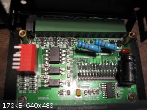
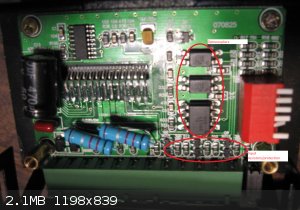
My Toshiba driver is just like the one in your link. Below is a photo of the inside of the driver:
Here's the Zyltech link from which I bought the motor/driver combo:
https://www.zyltech.com/store/p96/Nema_23_Stepper_Motor_w%2F...
[Edited on 4-2-2018 by Magpie]
The single most important condition for a successful synthesis is good mixing - Nicodem
|
|
|
Twospoons
International Hazard
Posts: 1282
Registered: 26-7-2004
Location: Middle Earth
Member Is Offline
Mood: A trace of hope...
|
|
So, looking at that I can see 3 optocouplers, and associated input resistors and protection. So you wont need the series resistors in your circuit
as the driver already has them built in.
Helicopter: "helico" -> spiral, "pter" -> with wings
|
|
|
Magpie
lab constructor
Posts: 5939
Registered: 1-11-2003
Location: USA
Member Is Offline
Mood: Chemistry: the subtle science.
|
|
Good thing you looked, Twospoons. Those resistors didn't look like anything I would recognize.
The single most important condition for a successful synthesis is good mixing - Nicodem
|
|
|
wg48
National Hazard
Posts: 821
Registered: 21-11-2015
Member Is Offline
Mood: No Mood
|
|
Ok so you have three independent lines of evidence that the module does not need input resistors. the link I posted the link you posted and Twospoon
view of the components on the board.
Will it be damaged by 5v? Your link suggests the input current is 5mA to 18mA. That’s low for most opto-couplers and 6V is close to 5V So I think
its low risk to work at 6V.
So try with the resistors in series with the signal lines removed and replaced with wire.
Hopefully it will be working now or at least the rotor will be locked.
From your comment about the LED flashing I think you will need to increase the frequency of the 555 more than ten fold. ie reducing the timing cap.
|
|
|
Magpie
lab constructor
Posts: 5939
Registered: 1-11-2003
Location: USA
Member Is Offline
Mood: Chemistry: the subtle science.
|
|
| Quote: Originally posted by wg48 |
From your comment about the LED flashing I think you will need to increase the frequency of the 555 more than ten fold. ie reducing the timing cap.
|
I can easily increase the flashing to a steady light by turning the 100K pot.
The single most important condition for a successful synthesis is good mixing - Nicodem
|
|
|
Magpie
lab constructor
Posts: 5939
Registered: 1-11-2003
Location: USA
Member Is Offline
Mood: Chemistry: the subtle science.
|
|
The 3 resistors are now out but the rotor is still free at 13.5vdc to the module.
The single most important condition for a successful synthesis is good mixing - Nicodem
|
|
|
wg48
National Hazard
Posts: 821
Registered: 21-11-2015
Member Is Offline
Mood: No Mood
|
|
First check the dip switches are in a suitable position, consult the info on the cover and the spec for the 6600 chip
Then check the voltage applied to the module with your multimeter ie the voltage to its supply Vcc and Gnd.
Then check the voltage between the +and - of the ena, dir signals on the actual terminal of the module.
Using your LED and resistor check you have pulses between the Pul+ and Pul- on the terminals of the module. Note no pulses should stop rotation but
not a locked rotor.
Check the voltage across the motor drives A+ to A- and B+ to B- at least one of them should have a voltage between them.
Remove the power to the module and check the resistance between A+ to A- and B+ to B- it should be a few ohms again across the terminals.
|
|
|
Twospoons
International Hazard
Posts: 1282
Registered: 26-7-2004
Location: Middle Earth
Member Is Offline
Mood: A trace of hope...
|
|
I would set the dip switches thusly:
s1,s2, : ON , s3 : OFF -> put driver in single step mode
S4: OFF , S5,S6 : ON -> 1A motor current ( a good starting point)
You should be able to see the current on the meter of that nice power supply you have, if the driver is active. You should see pretty much the same
current whether the motor is turning or not.
Looking at the docs it may be the driver is set up to be enabled by default, given the diagrams that leave the enable disconnected. Try that too.
Helicopter: "helico" -> spiral, "pter" -> with wings
|
|
|
Magpie
lab constructor
Posts: 5939
Registered: 1-11-2003
Location: USA
Member Is Offline
Mood: Chemistry: the subtle science.
|
|
| Quote: Originally posted by wg48 |
First check the dip switches are in a suitable position, consult the info on the cover and the spec for the 6600 chip |
The dip switches have been set per Twospoons' next post. Ie,
S1, S2: ON
S3, S4: OFF
S5, S6: ON
| Quote: Originally posted by wg48 |
Then check the voltage applied to the module with your multimeter ie the voltage to its supply Vcc and Gnd |
.
15 vdc
| Quote: Originally posted by wg48 |
Then check the voltage between the +and - of the ena, dir signals on the actual terminal of the module. |
both are 5vdc
| Quote: Originally posted by wg48 |
Using your LED and resistor check you have pulses between the Pul+ and Pul- on the terminals of the module. Note no pulses should stop rotation but
not a locked rotor. |
using no resistor: pulsing
w/680Ω: no pulsing
| Quote: Originally posted by wg48 |
Check the voltage across the motor drives A+ to A- and B+ to B- at least one of them should have a voltage between them. |
no voltage across either
| Quote: Originally posted by wg48 |
Remove the power to the module and check the resistance between A+ to A- and B+ to B- it should be a few ohms again across the terminals.
|
A+ to A- = 0v
B+ to B- = 0v
measured with a meter that reads 10 Ω midscale
Zyltech data sheet values: 1.2Ω for each phase
A Toshiba 6600 document that might be of value:
file:///C:/Users/Owner/Downloads/TB6600HG_datasheet_en_20160610%20(2).pdf
The single most important condition for a successful synthesis is good mixing - Nicodem
|
|
|
aga
Forum Drunkard
Posts: 7030
Registered: 25-3-2014
Member Is Offline
|
|
Not sure if this is relevant, but the stepper drivers i have are opto-isolated, so basically you have to put the all the N- to ground or sticking 5v
on the N+ does nothing.
|
|
|
Twospoons
International Hazard
Posts: 1282
Registered: 26-7-2004
Location: Middle Earth
Member Is Offline
Mood: A trace of hope...
|
|
Try disconnecting ENA. It may work backwards ie no volts = on and 5V = off.
Helicopter: "helico" -> spiral, "pter" -> with wings
|
|
|
wg48
National Hazard
Posts: 821
Registered: 21-11-2015
Member Is Offline
Mood: No Mood
|
|
Well you appear to have the right voltages on the terminals of the module.
You did not give the resistance across the motor terminal but given the results of the voltage tests and no supply current drawn its irrelevant.
Yes try switching off the ENA signal, try disconnecting the 6v battery, try various combinations of the dip switches each time check for a locked
rotor and significant Vcc current on your power supply.
You could check the voltages on the pins of the 6600 chip inside your module if you can work out what they should be from the data sheet but it will
probably just confirm the Module is faulty.
Assuming you did the tests correctly Its probable the module is faulty. Given a new module costs about $7 you may be at the point to order a new one
from China. To avoid the wait you can buy from the US but it will probably double or more the price.
One thing talk your EE buddy into checking it out on site. A fresh pair of eyes and a different brain may spot a problem.
Even a half brain dead EE is probably better than no EE LOL.
If you do order a new one make certain you have an interface spec for it in English. You would not buy new glassware without knowing what the size of
the ground joints were. A spec for the module not the IC it contains.
[Edited on 5-2-2018 by wg48]
|
|
|
Magpie
lab constructor
Posts: 5939
Registered: 1-11-2003
Location: USA
Member Is Offline
Mood: Chemistry: the subtle science.
|
|
wg48, sorry for the mistake of omission on my last post. Here is the correction:
phase resistances:
A+ to A-: 0Ω
B+ to B-: 0Ω
These were measured with an ohm meter reading 10Ω at midscale.
Zyltech spec: 1.2Ω for each phase
I am getting the rest of the requested information now.
[Edited on 6-2-2018 by Magpie]
[Edited on 6-2-2018 by Magpie]
[Edited on 6-2-2018 by Magpie]
The single most important condition for a successful synthesis is good mixing - Nicodem
|
|
|
wg48
National Hazard
Posts: 821
Registered: 21-11-2015
Member Is Offline
Mood: No Mood
|
|
When the module is not powered, I would not expect the resistance across the phases with the motor connected to be significantly different than the
resistance of the windings, on the assumption that the transistors of the H bridge of the module are enhancement mode and the ohmmeter has
insufficient OC voltage to cause the significant conduction through the H bridge diodes or measure zero ohms.
I suggest you check the resistance of the motor windings disconnected from the module and check the resistance across the modules phase outputs (again
with the module un-powered and this time with the motor disconnected) and preferable check the resistance of a 1.2ohm resistor to determine the
validity of your meter reading.
I think if the resistance across the phases (A+ to A- and B+ to B-) of an unpowered module (motor disconnected) is less than 1 ohm it is probably
faulty.
|
|
|
Magpie
lab constructor
Posts: 5939
Registered: 1-11-2003
Location: USA
Member Is Offline
Mood: Chemistry: the subtle science.
|
|
| Quote: Originally posted by wg48 |
I suggest you check the resistance of the motor windings disconnected from the module and check the resistance across the modules phase outputs (again
with the module un-powered and this time with the motor disconnected) and preferable check the resistance of a 1.2ohm resistor to determine the
validity of your meter reading.
I think if the resistance across the phases (A+ to A- and B+ to B-) of an unpowered module (motor disconnected) is less than 1 ohm it is probably
faulty.
|
I have a small NEMA 17 Mineba stepper motor, proven operable, that also reads 0 Ω across the phases. I measured the smallest resistor I have, 22Ω,
and it also reads 0 Ω. It is clear that my meter cannot read small resistances. Therefore, I think all of my 5 stepper motors are good. The fault
must be with the module.
Here's the answers to your other questions:
1. Switching the ENA signal off made no change.
2. My EE buddy is a "power" man. Only thing he said was "believe the experts."
3. Changing around all the dip switches made no difference.
I will buy a new Toshiba module. This is not a problem.
The single most important condition for a successful synthesis is good mixing - Nicodem
|
|
|
| Pages:
1
..
5
6
7
8
9 |


