| Pages:
1
2
3
4
5
..
9 |
Magpie
lab constructor

Posts: 5939
Registered: 1-11-2003
Location: USA
Member Is Offline
Mood: Chemistry: the subtle science.
|
|
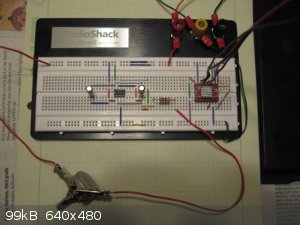
Here's a couple pictures. The ground bus is the top row. The 5v bus is the 2nd row down. The 12v bus is one row up from the bottom row. If these
pictures aren't adequate I'll take some more tomorrow when I can get more light.
I hooked it up to the motor this afternoon. The rpm was variable from 9.2 to 46. As varmint predicted it goes through about 3 really rough spots on
the way up (high vibration). But this should not be a problem for the planned application. I measured the voltage at the 1st lead from the left at
the driver. It was 2.5v at 9.2 rpm and 3v at 46 rpm. The pot position at 9.2 rpm is full ccw and at 46 rpm is about 90% of full cw. Above that the
motor stops.
I will post another YouTube video tomorrow showing the mixer in operation. I'm thinking now that it would be useful to be able to reach higher
speeds, say at least 200 rpm. The torque is very good, at least at the speeds attained so far.
Can't you get YouTube where you live?
[Edited on 27-11-2014 by Magpie]
The single most important condition for a successful synthesis is good mixing - Nicodem
|
|
|
diddi
National Hazard
Posts: 723
Registered: 23-9-2014
Location: Victoria, Australia
Member Is Offline
Mood: Fluorescent
|
|
what is the value of the capacitor to the right of the 555
the motor stopping is the problem a referred to about the 555 freezing up. the 22 ohm resistor should have stopped that.
oh and the LEDs will appear constantly on because the circuit design does not have the "clock" pulse from pin 3 set at 50%on/50%off (the "Duty cycle")
it is more like 99%/1% so LEDs appear on always. (needs more components to get 50% duty cycle
[Edited on 27-11-2014 by diddi]
[Edited on 27-11-2014 by diddi]
|
|
|
Magpie
lab constructor
Posts: 5939
Registered: 1-11-2003
Location: USA
Member Is Offline
Mood: Chemistry: the subtle science.
|
|
The value of both capacitors is 47µF. All components are per your schematic.
The single most important condition for a successful synthesis is good mixing - Nicodem
|
|
|
Varmint
Hazard to Others
Posts: 264
Registered: 30-5-2013
Location: Near Atlanta, GA
Member Is Offline
Mood: No Mood
|
|
Magpie:
At the upper speed limit, does the motor continue to whine with pulses, or is this the 555 locking up and failing to provide pulses as /Diddi
describes?
If there is whining still present, then the reason for stoppage is the drive not being able to counteract the stepper inductance.
Another source of trouble with steppers is related to their "need" the reach the next step cleanly and quickly. If the load will not allow a step to
the next position rapidly, then the motor can get locked up in mid-step so to speak, where the next phase change doesn't happen at the proper time
with regard to the angular position, so suffering a loss in torque.
In general, the best approach is to keep the mass to the minimum possible, but beyond that the ideal solution is to use a flexible coupler with
elastomeric inserts (rubber or synthetics). This allows the motor to index solidly to the next position, (compressing the insert), and the insert
then moves the load. This decoupling of the load dynamic requirements can help quite a bit, but beyond this we are again moving into territory where
enhanced motor drives become a requirement.
You mention the costs might be getting a bit high, I'm not sure what high means in context, but industry bought couplers can be very expensive
(especially from McMaster-Carr and the like ) and pretty soon you have a setup costing hundreds, yet still nowhere near optimized. For optimal motor
drive you might want to look at something like this:
http://www.geckodrive.com/geckodrive-step-motor-drives/g250x...
Coupled with an appropriately selected power supply, this drive (the cheapest Gecko offers) is still full featured enough to drive your motor to its
fullest potential. For your purposes, you can set the rotation to fixed CW or CCW, the simply provide step pulses to set the speed.
All the best, and Happy Thanksgiving!
DAS
|
|
|
Magpie
lab constructor
Posts: 5939
Registered: 1-11-2003
Location: USA
Member Is Offline
Mood: Chemistry: the subtle science.
|
|
Quote: Originally posted by Varmint  | Magpie:
At the upper speed limit, does the motor continue to whine with pulses, or is this the 555 locking up and failing to provide pulses as /Diddi
describes?
If there is whining still present, then the reason for stoppage is the drive not being able to counteract the stepper inductance.
|
Thanks Varmint and I will get to your questions as soon as possible. Right now I'm trying to placate my wife as she is being a major grump because
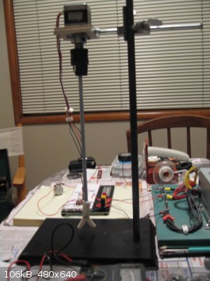
it's Thanksgiving and I'm still working on my projects. The above photos show the stepper motor stuff all over the kitchen table. Luckily we have
been invited to my son's in-laws for the Thanksgiving meal!
Thanks and the same to you. 
The single most important condition for a successful synthesis is good mixing - Nicodem
|
|
|
Magpie
lab constructor
Posts: 5939
Registered: 1-11-2003
Location: USA
Member Is Offline
Mood: Chemistry: the subtle science.
|
|
Here's a video of the stepper motor operation through its full range of speed: 9.2 to 46 rpm.
https://www.youtube.com/watch?v=bXObV1q-FzQ&feature=yout...
The single most important condition for a successful synthesis is good mixing - Nicodem
|
|
|
diddi
National Hazard
Posts: 723
Registered: 23-9-2014
Location: Victoria, Australia
Member Is Offline
Mood: Fluorescent
|
|
it says the video is private 
|
|
|
Magpie
lab constructor
Posts: 5939
Registered: 1-11-2003
Location: USA
Member Is Offline
Mood: Chemistry: the subtle science.
|
|
The YouTube videos below should be available to the public now. My error was in not toggling the "publish" button following the uploads. Let me know
if you can't view them.
http://youtu.be/xD-XZukfib0
http://youtu.be/bXObV1q-FzQ
If anyone knows how I can increase the top speed (46 rpm) significantly without spending more than $25 please let me know.
The single most important condition for a successful synthesis is good mixing - Nicodem
|
|
|
Varmint
Hazard to Others
Posts: 264
Registered: 30-5-2013
Location: Near Atlanta, GA
Member Is Offline
Mood: No Mood
|
|
OK, that was a textbook demonstration of the symptoms I tried to describe regarding driver issues.
Where it lost solid direction and stuttered around "hunting" to get back in sync is exactly where the drive voltage became insufficient to counteract
the inductance of the windings. What is not immediately clear is if the fully stopped condition at the end was still energized, or if it had in fact
locked up the 555 and pulses were no longer being generated. It would be an interesting coincidence that the highest frequency to maintain
synchronous stepping just so happened to coincide with the highest frequency before the 555 latched up.
So, the only thing for certain at this point is you need a higher drive voltage to the motor, and perhaps a power supply with a more robust current
capability as well. But what I can promise is you won't be getting much higher speeds without very significant driver changes, it's simply the nature
of the beast. The motor you are using should be capable of several hundred RPM at a minimum with a good driver (and adequate power supply), so your
only real solution is to invest in the driver I mentioned, or abandon the stepper approach entirely.
Please don't be tempted to try an Arduino with a stepper shield or any other approach, you need a quality driver. That is to say, if you were to use
an Arduino and a typical low-dollar motor shield, you will still be plagued with an upper RPM limit in the range you are currently seeing, the trick
lies in a purpose built motor driver that modifies the pulse duration and modulates the much higher drive voltage (and thereby current) required to
achieve high speed operation. Again, for a quality driver you can expect to need a minimum of 4X the motor "rated" voltage, and sometimes up to 20X!
All of this is explained well on the Gecko site, so even if you choose not to use their driver, you might want to read up on how steppers need to be
driven, if not just for the learning experience, perhaps future applications.
I have two stepper stages that were used to perform final focus of laser diode lens assemblies, they exhibit very fine control (400 steps per
revolution driving a 10 turn per inch precision ball screws). The motors are rated at 3.6V and 2.8A per phase, yet their drivers are supplied with
48V from a very stout supply, or 13.33x the rated motor voltage! If you tried to run them of a simple switched 48V they would draw huge amounts of
current to the point of destruction. Again, the driver in use is "intelligent" and modifies the step waveforms and dynamically throttles the current
to allow the motors to perform well, and remain cooler than if they were driven from a simple h-bridge running at the "rated" current and voltage.
I know a great deal of this seems counter intuitive, but steppers are really quite hard to drive when large variations in speed and torque are
required. It all stems from the inductive reactance of the coil windings, and there are no simple solutions unfortunately. I've achieve speeds of
100RPM with a simple H-Bridge, but the torque was woefully inadequate for driving much more than the motor shaft itself.
DAS
|
|
|
Varmint
Hazard to Others
Posts: 264
Registered: 30-5-2013
Location: Near Atlanta, GA
Member Is Offline
Mood: No Mood
|
|
http://www.geckodrive.com/step-motor-basics
Link to Gecko's stepper motor basics.
DAS
|
|
|
Varmint
Hazard to Others
Posts: 264
Registered: 30-5-2013
Location: Near Atlanta, GA
Member Is Offline
Mood: No Mood
|
|
https://www.sparkfun.com/products/11876
This is what I would consider the absolute minimum driver that attempts to address the difficulties of driving stepper motors. The current capability
is pretty low, but it does offer some modulation capabilities that might extend your RPM capability. There are similar products from other
manufacturers, but none of these cheaper units address ALL the issues encountered when attempting to extract maximum performance from a stepper.
Best of luck.
DAS
|
|
|
Magpie
lab constructor
Posts: 5939
Registered: 1-11-2003
Location: USA
Member Is Offline
Mood: Chemistry: the subtle science.
|
|
Varmint thanks so much for that very complete and well written analysis. I now have some fundamental decisions to make, ie, do I want to put the
money needed into this to make it a truly useful high torque-low speed mixer.
The torque is excellent and this is what is driving me to complete the development work. But I also have another problem to solve not mentioned so
far: shaft wobble. But this is not an electronics or motor problem. The stepper motors I salvaged from the copier all have a gear that is
press-fitted to the shaft. My machinist tried to remove this with a puller but was unsuccessful - his puller didn't fit right. So we just left it on
and secured the collar with a set screw. This does not give the near perfect shaft alignment that is required to prevent wobble. The gear threads are
worm configuration and this makes things worse.
I will publish one more video showing the mixer stirring a table salt slurry.
If I purchase the gecko motor driver ($19.95) could I still use the remainder of my existing electronics? Or would I need a new circuit?
The single most important condition for a successful synthesis is good mixing - Nicodem
|
|
|
Varmint
Hazard to Others
Posts: 264
Registered: 30-5-2013
Location: Near Atlanta, GA
Member Is Offline
Mood: No Mood
|
|
The cheapo $19.95 driver is from Sparkfun. Yes, it should work fine, the clock pulses from the 555 will do nicely.
Keep in mind this doesn't address any of the resonance issues. You would normally run in microstep mode to reduce or eliminate resonance at slow
speeds, but as you need to increase speed, circuitry would switch the driver to full step mode. This driver won't do that by itself, which is why I
say this is still a sub optimal approach.
In te past I've used several methods to remove stuck pulleys, splitting the side parallel to the shaft with a dremel cutoff wheel then using a
screwdriver to pry the slot wider works well. Another for aluminum and plastic pulleys is to crush the pulley with a shop press (the assumption being
the motor shaft is far harder than the pulley material). Rotate 90 degrees and crush again, repeat, before long it'll be loose as a goose.
DAS
|
|
|
Magpie
lab constructor
Posts: 5939
Registered: 1-11-2003
Location: USA
Member Is Offline
Mood: Chemistry: the subtle science.
|
|
Thanks for those suggestions on removing the worm gear. I'm going to first consult with my machinist but I have a Dremel and should be able to remove
the gear as you say.
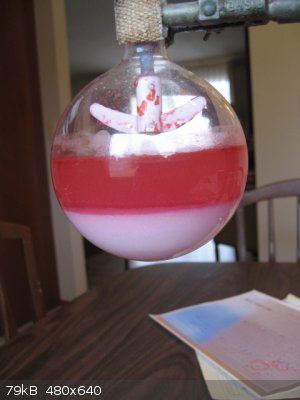
Here's a picture of the salt slurry in a 500 ml RBF. In the movie I'm stirring that slurry easily with the stepper motor.
https://www.youtube.com/watch?v=gHf0w4nliUY
Right now I'm using a 12vdc power source. If I increase this to a higher voltage to get more speed, say 35vdc, will the Sparkfun driver and my
remaining electronics still be adequate?
The single most important condition for a successful synthesis is good mixing - Nicodem
|
|
|
Varmint
Hazard to Others
Posts: 264
Registered: 30-5-2013
Location: Near Atlanta, GA
Member Is Offline
Mood: No Mood
|
|
Frankly I'm surprised it's driving all that mass as well as it is.
I don't really know much about the sparkfun driver other than they are popular in the DIY CNC crowd, being a mid-ground between a bare h-bridge and an
advanced drive like the Geckos and others. I notice a current limit pot, and I'm sure you can find info on their site regarding suggested voltage and
current control settings.
Seems like a friendly community on their forum, please take the time to ask questions there before diving in.
DAS
|
|
|
Varmint
Hazard to Others
Posts: 264
Registered: 30-5-2013
Location: Near Atlanta, GA
Member Is Offline
Mood: No Mood
|
|
Hold the presses, describe the driver chip you have, I think you can improve it with a little bit of effort.
|
|
|
Magpie
lab constructor
Posts: 5939
Registered: 1-11-2003
Location: USA
Member Is Offline
Mood: Chemistry: the subtle science.
|
|
Here's the one I installed:
http://www.ebay.com/itm/121427026317?_trksid=p2060778.m2749....
I think I have the shaft wobble problem solved, once I get that gear cut off the 5mm motor shaft. I just ordered a 5mm x 3/8" shaft coupler from 3D
Printer Webstore. By using a 3/8"-24 ss partially threaded bolt I should have a good connection. The aluminum coupler is spiral cut to compensate
somewhat for misalignment.
My motor is a Minebea 17PM-J type so is a custom motor and there are no published speed-torque curves that I could find (I have written to Minebea to
see if they can divulge this data). However, in looking at the data for 17PM-J149U which I feel is likely close in specifications (my motor weighs
300g, is unipolar, and is rated for 1.14 amps). The speed-torque curve for this motor shows a torque of 250 mNm at 0 Hz which does not drop off until
1000Hz.
http://www.eminebea.com/content/html/en/hybrid_list/pdf/17PM...
I calculate the rpm at 1000Hz as follows:
1000Hz = 1000/200 rev/s = 5*60 rev/min = 300 rpm
Even at 600 rpm (2000 Hz) the torque has only fallen off to ~225 mNm.
[Edited on 30-11-2014 by Magpie]
The single most important condition for a successful synthesis is good mixing - Nicodem
|
|
|
Varmint
Hazard to Others
Posts: 264
Registered: 30-5-2013
Location: Near Atlanta, GA
Member Is Offline
Mood: No Mood
|
|
OK, forget the sparkfun driver, you have an equivalent.
The thing to do is to raise the voltage incrementally to see how far you can take it before heat becomes an issue for the chip or motor.
Did they provide any instructions for setting the current with the small pot?
In any event, you already have the middle-capability driver, I'm sorry for not paying more attention earlier.
|
|
|
Magpie
lab constructor
Posts: 5939
Registered: 1-11-2003
Location: USA
Member Is Offline
Mood: Chemistry: the subtle science.
|
|
| Quote: Originally posted by Varmint |
The thing to do is to raise the voltage incrementally to see how far you can take it before heat becomes an issue for the chip or motor.
|
What do you mean by "raise the voltage?" Ie, do you mean use a higher supply voltage than the current 12vdc, or do you mean turn up the big pot? I
have already turned the big pot up until the motor stops at ~90% of its cw travel.
Incidentally I think this big pot is a 2k rather than the 20k I ordered.
No instructions were provided. I notice there is a very small screw on the driver board. Is this the "small pot" you are refferring to? I have not
touched it and do not know at what position it is set.
| Quote: Originally posted by Varmint |
In any event, you already have the middle-capability driver, I'm sorry for not paying more attention earlier. |
No problem. I have not ordered any new drivers as yet.
[Edited on 30-11-2014 by Magpie]
[Edited on 30-11-2014 by Magpie]
[Edited on 30-11-2014 by Magpie]
The single most important condition for a successful synthesis is good mixing - Nicodem
|
|
|
Varmint
Hazard to Others
Posts: 264
Registered: 30-5-2013
Location: Near Atlanta, GA
Member Is Offline
Mood: No Mood
|
|
OK, you should have a power supply providing juice for the 555 and the driver board.
Thje driver board has and onboard regulator so it's logic runs at 3.3 or 5V, and I'm not sure if that is fixed, or a user switchable option. In any
even, you want to increase the voltage to the driver board, so it can in turn provide higher voltage to the motor.
Since the motor is an inductive reactance, when you apply a higher voltage, the motor doesn't really "see" this higher voltage (so to speak) until the
current stored in the inductor builds up on it's way to saturation, and this is where the current adjust pot comes in.
It works (the tiny pot that does resemble screw I suppose on the driver board) by providing a reference to what current the motor is "seeing" as
sensed by the current sense resistors on the driver board. When it reaches the peak allowed current, the driver will modulate the step pulse width so
excess current is avoided.
As an experiment, you can leave your supply voltage at 12V, and vary the position of this pot to see if you can reach a higher peak RPM. Note a
smooth steady increase in frequency (from the pot controlling the 555) will result in higher attainable speeds, you will have little luck trying to
start at high speed.
You will probably find higher driver voltage is required, and you might even want to try tweaking the tiny pot to see if it can improve the speed
further with each increment in supplied voltage. At some point vibration naturally disappears since the motor isn't really trying to stop and start
with each step, but carried through to the next position by the flywheel effect of the attached mass.
DAS
|
|
|
Magpie
lab constructor
Posts: 5939
Registered: 1-11-2003
Location: USA
Member Is Offline
Mood: Chemistry: the subtle science.
|
|
I set 555 pot at low speed then turned the pot on the board. At first it seemed to increase in speed. So I slowly turned the 555 pot up to get
maximum speed (just before cutout). I measured the speed to be 48 rpm. The previous high was 46 rpm - so no significant increase this way. At
present I do not have a higher dc voltage supply than 12v. When I can find one I will run more tests. I see the board is rated up to 35vdc. Any
other suggestions at this time?
The single most important condition for a successful synthesis is good mixing - Nicodem
|
|
|
Varmint
Hazard to Others
Posts: 264
Registered: 30-5-2013
Location: Near Atlanta, GA
Member Is Offline
Mood: No Mood
|
|
Now keep in mind you said the highest speed it attained was near the limit of the pot, meaning the 555 as presently configured can't provide the
needed higher frequencies. Try changing the timing cap to 1/2 it's present value, this will double the highest frequency
Beyond that, no other suggestions, you are still in the zone where the applied voltage is unable to "work past" the inductive reactance of the motor.
|
|
|
Magpie
lab constructor
Posts: 5939
Registered: 1-11-2003
Location: USA
Member Is Offline
Mood: Chemistry: the subtle science.
|
|
OK, I'll try that. Is that the cap across pins 7 & 8?
The single most important condition for a successful synthesis is good mixing - Nicodem
|
|
|
Varmint
Hazard to Others
Posts: 264
Registered: 30-5-2013
Location: Near Atlanta, GA
Member Is Offline
Mood: No Mood
|
|
Yes, but I'm used to seeing different wiring for astable 555's.
http://home.cogeco.ca/~rpaisley4/LM555.html#3
|
|
|
Magpie
lab constructor
Posts: 5939
Registered: 1-11-2003
Location: USA
Member Is Offline
Mood: Chemistry: the subtle science.
|
|
Yes! Replacing the 47µF with a 22µF cap at pins 7 & 8 yielded an rpm of 100!
It is not whining so loudly anymore, in fact I can barely hear it.
The span on the big pot has been decreased. Does this mean I could use a smaller pot? It seems it was serendipity that Digi-Key sent me a 2k pot
instead of the 20k pot that I ordered.
Just tell me how to reconfigure to what you recommend.
[Edited on 1-12-2014 by Magpie]
The single most important condition for a successful synthesis is good mixing - Nicodem
|
|
|
| Pages:
1
2
3
4
5
..
9 |


