| Pages:
1
2
3
4 |
blazter
Hazard to Self

Posts: 71
Registered: 3-9-2002
Member Is Offline
Mood: No Mood
|
|
homebrew aspirator
After seeing various recirculating aspirator setups i've noticed that the authors of the howtos didn't mention where they actually obtained the
aspirator unit. Now, i have seen them for sale at online vendors, but im wondering if a similar unit could be constructed from readily available
hardware store supplies? I'm thinking about a "T" connector and a few reducers, or simply making a "T" by drilling some copper tubing and soldering a
smaller tube in it. Is this more work than its worth assuming it MIGHT work? Also, anyone have any suggestions for dimensions/reduction ratios?
|
|
|
Polverone
Now celebrating 21 years of madness
Posts: 3186
Registered: 19-5-2002
Location: The Sunny Pacific Northwest
Member Is Offline
Mood: Waiting for spring
|
|
Given that you can get a real aspirator for something like $10, it does seem like more effort than it's worth. I have a soft spot in my heart for
homemade equipment, though.
Actually, here's another question: just how would you go about attaching an aspirator to a normal home faucet, or even an outdoor spigot? My faucets
don't have the nifty ridged, tapering connectors that lab ones do.
|
|
|
NERV
Hazard to Others
Posts: 152
Registered: 22-9-2002
Location: USA
Member Is Offline
Mood: Fluorinated
|
|
Here is a possible way to make a home made aspirator.

|
|
|
blazter
Hazard to Self
Posts: 71
Registered: 3-9-2002
Member Is Offline
Mood: No Mood
|
|
Thanks for the info NERV. A nice drawing but may i ask a quick question about the dimensions? Specifically, what diameter does the PVC pipe have to
be that receives the water from the pen tube? I assume something like 1/2 inch would be too large.
The logistics of hooking up flexable tubing or rigid PVC pipe to a hose or threaded faucet shouldn't be too difficult. It's possible to buy threaded
adapters to flexable PVC or one could go the really cheap way and cut off the end bit of a hose and use hose clamps to secure it to a piece of 1/2inch
or possibly 3/4inch rigid PVC (i'm not sure off the top of my head which would fit better).
|
|
|
NERV
Hazard to Others
Posts: 152
Registered: 22-9-2002
Location: USA
Member Is Offline
Mood: Fluorinated
|
|
Well I don’t have a pen to measure the diameter of right now, but I would say the receiving should be about a 1/4 of an inch, or so wide.
|
|
|
Organikum
resurrected
Posts: 2329
Registered: 12-10-2002
Location: Europe
Member Is Offline
Mood: busy and in love
|
|
perhaps this helps
the pics which have been here are in the attachment of the overnext post. Some confusion, sorry.
ORG 
[Edited on 21-5-2003 by Organikum]
|
|
|
Organikum
resurrected
Posts: 2329
Registered: 12-10-2002
Location: Europe
Member Is Offline
Mood: busy and in love
|
|
addon
Some more information on the pictures.
The industrial device is a liquid driven one (water mostly). It is intended to work with a closed end, says it is connected to a tube and not just
left open to air. So if this design is adapted it´s preferable to keep the end below the water surface for optimal results.
The second one is originated in a SIEMENS portable vacuum device and operates with compressed air. There is in this special case no difference to a
liquid driven device, except the diameter of the nozzle which should be bigger with water.
What diameter shall the the nozzle have by principle? Depends on your water supply. It should be as wide as possible without getting a reasonable
lowered pressure on the water line measured min. 50cm away from the aspirator. It makes sense to determine this before building the aspirator. Mostly
you won´t need or want the max. nozzle as you won´t need these amounts of air sucked out fast. The reachable vacuum stays the nearly same.
If there is interest I can post some more information on the topic.
Here is a link to the in my eyes best webpage on chemical engineering including information on this too.
Don´t miss the distillation pages! CheResources
|
|
|
Organikum
resurrected
Posts: 2329
Registered: 12-10-2002
Location: Europe
Member Is Offline
Mood: busy and in love
|
|
as the pics are gone
with the ftp I had my files on, I add them here as attachment.
I packed some more construction drawings and two tables for vacuum to reach with what pump.
sorry for the inconveniance and the three posts in line.
ORG
Attachment: Aspiratores.rar (116kB)
This file has been downloaded 3629 times
|
|
|
blazter
Hazard to Self
Posts: 71
Registered: 3-9-2002
Member Is Offline
Mood: No Mood
|
|
Cool
Wow, didnt expect full blueprints! very good info indeed. If i get time I think i'll try constructing one from pvc tubing and the pen tube method.
Currently I'm spending my free time on the tube furnace project (the thermocouple electronics and MoO3 is going to get ordered soon for that)
|
|
|
Organikum
resurrected
Posts: 2329
Registered: 12-10-2002
Location: Europe
Member Is Offline
Mood: busy and in love
|
|
For a quick buildt but functional device
You may use this for dimensioning:
xx
It´s in millimeters
The aspirator ready buildt looks like this if metal tube is used:
xx
This is functional, and tested. There are optimisations possible of course but for most applications this will do fine. For higher vacuum I would
suggest to stage up a fridge compressor in line with the aspirator. This setup should deliver effective vacuum in the range of <15 torr.
Thats better as many of the praised "yellow jacket" pumps are able to do for costs below 50?/$ including all tubing.
As soon as I have some spare time I will do some tests on optimizing an aspirator, as I am now sure that the vapour pressure of water doesn´t limit
the maximal reachable vacuum, but the velocity does. I will try to adapt some principles of Viktor Schauberger´s work on water and vortexes, where he
describes ways to reduce the resistance in tubes to near zero. It´s no quack, water powered electricity plants working by these principles exist.
Has anybody a bright idea how to calibrate a vacuumeter? To build one by means of a thermocouple is easy.....
ORG
xx - pics gone. I repost them as attached file - have a look down the thread. 
[Edited on 8-4-2003 by Organikum]
|
|
|
PoDuck
Harmless
Posts: 8
Registered: 17-2-2003
Member Is Offline
Mood: No Mood
|
|
I think that the previous post is actually a good design. Basically, you need to make a venturi design, and the professional ones and the one above
seem to have a chamber like design to keep the water from having a chance to leave the inlet hole so easily. Before I got to the bottom of the page,
and saw this design, I was going to suggest a design that would work by having a male threaded end to work with the normal household faucet, and
instead of a T, have kind of a y shape like the attached picture. This would create less turbulence at the entry point since the angle is lower where
the water would hit, and would be less likely to find it's way up the tube to your chemicals.
<img src="http://poduck.dyndns.org/aspirator.gif" width="127" height="300"><br />
With this, you could make it out of copper tubing and solder. It would not be as unreactive with most corrosive gasses as PVC, but it would be more
sturdy.
[Edited on 18-2-2003 by PoDuck]

|
|
|
Organikum
resurrected
Posts: 2329
Registered: 12-10-2002
Location: Europe
Member Is Offline
Mood: busy and in love
|
|
Venturi and copper
Actually all aspirators use the venturi principle to function. And you may use copper or what you like to use the material is not critical - if you
fear corrosion paint it.
But sorry to tell, your design won´t work as it misses the nozzle for velocity and more important the outlet has an far to wide diameter. The air
would just flow up at the sides and you have no vacuum at all. The smaller diameter of the outlet is the seal. If you would like to use the whole
diameter of the waterline you would have to widen the part where the air inlet is for applying the venturi and it would be not very strong for lacking
velocity. The form of the air inlet isn´t critical at all - suckback is prevented by an separate one-way valve (ball-type).
I think also you have an misconception regarding the difference between an aspirator and an air-pump which are very similar but not identical:
A aspirator is for applying and holding upright of a vacuum what includes only very little airflow whereby an air-pump is optimized for processing
maximal amounts of air what includes an permanent airflow. One works on a maximal pressure difference the other on maximal flow.
There is naturally no exact borderline between the two devices.
Essential for an aspirator are:
- A nozzle for the working fluid gaining velocity.
- A chamber where the venturi is applied.
- A narrowing working as seal for preventing pressure equalization.
Complaints please to Mr Venturi who made this up.
ORG
|
|
|
Organikum
resurrected
Posts: 2329
Registered: 12-10-2002
Location: Europe
Member Is Offline
Mood: busy and in love
|
|
missing pictures repost
the missing pics from above as attached file.
Attachment: Aspiratores.rar (17kB)
This file has been downloaded 1999 times
|
|
|
Eliteforum
National Hazard
Posts: 571
Registered: 18-11-2002
Location: United Kingdom
Member Is Offline
Mood: Enjoying the journey
|
|
I have various copper connectors (compression fittings) if anyones intrested?
Here's a list of what I have:
x1 15mm screw in end cap
x2 15mm T connectors
x1 15mm to 22mm ball valve
x1 15mm 90degree elbow joint
x1 15mm to 22mm reducer/enlarger
x1 22mm endcap with a all valve in the end.
x1 15mm endcap
All these are brand new and haven't been used.
If your intrested, let me know.
All that glitters isn't gold.
|
|
|
Organikum
resurrected
Posts: 2329
Registered: 12-10-2002
Location: Europe
Member Is Offline
Mood: busy and in love
|
|
thanks for the offer Eliteforum, but I doubt it being economically making sense to send the parts in the czech republic....
(in the end the customs even want me to pay duties on it)
Found this:
cute, isn´t it?
[Edited on 21-5-2003 by Organikum]
|
|
|
Organikum
resurrected
Posts: 2329
Registered: 12-10-2002
Location: Europe
Member Is Offline
Mood: busy and in love
|
|
update
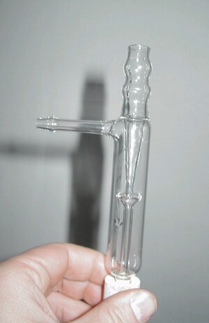
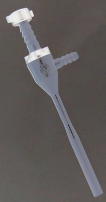
This is a bought aspirator (the picture is negative for security reasons - and for that it may not look so unbelievable boring...)
And this is this aspirator disassembled - naked to the bone - huh!
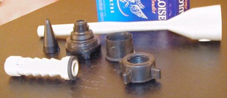
The one mysterious part - right in the middle row of three - is a rubber thingie which shall work as suckback inhibitor - a primitive integrated
one-way valve. This part in reality diminishes the vacuum and power overall significantly and suckback takes place nevertheless. Thats astonishing for
a professional laboratory device.
I removed the rubbershit and a cheap ballvalve from the aquarium supply actually WORKS inhibiting suckback.
If there is interest I can measure the parts and post the dimensions.
|
|
|
n00dle
Harmless
Posts: 1
Registered: 5-9-2003
Location: sdf
Member Is Offline
Mood: No Mood
|
|
A good fridge compressor will do a 1 torr vaccum. (Boil water at room temperature.)
Problem is, it's designed to work in a hermetically sealed environment. If you use it in normal atmosphere, the compressor side will make the
water in the air freeze, and then turn the insides of the compressor into mush as it trysto act as an ice cube blender.
I'd REALLY be interested if someone could suggest a way to say, remove the compressor, and regarge it, and use it to drive another device as a
vaccuum pump. Like a passive system, so the fridge compressor will be happy in a 0% water environment, yet you can still passively use it for any
humidity range.
Just a thought
|
|
|
Organikum
resurrected
Posts: 2329
Registered: 12-10-2002
Location: Europe
Member Is Offline
Mood: busy and in love
|
|
Never heard of this freezing problem before. You should tell this the manufacturers of rotary vain vacuumpumps - they will be glad to get to know why
their machines are not working... LOL
Or short and cruel:
NONSENSE.
Realistic are 50torr by using a single fridge compressor, 10torr by using two staged. You may be able to get it better but thats what you can expect
with a not much effort rig.
|
|
|
Tacho
National Hazard
Posts: 582
Registered: 5-12-2003
Member Is Offline
Mood: No Mood
|
|
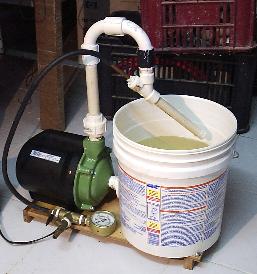
Vacuum station/ aspirator - homemade.
My miserable junkyard refrigerator vacuum pump failed when I needed it most!
I decided to build a vacuum station. Went to the hardware store, and built this:

The pump is 1/4 hp and I found out that it needed a bigger water deposit, otherwise water would splash all over.
I tought that it would be easy to built an aspirator using PVC fittings so I've built something like this:
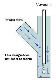
I found out it does not work! I don't know why! I have seens schematics of comercial aspirators, but they don't make sense. Why would a flow
of liquid suck air around it to funnel it into the exit tube? There has to be some trick there!
Does anybody have any experience building aspirators with hardware store materials? Or know exactly how they work? Please, armchair scientists,
don't give me something stupid like "it's the Bernoille principle, my dear".
My work until now looks like this (notice the Y conection of my failed aspirator):
|
|
|
Hermes_Trismegistus
National Hazard
Posts: 602
Registered: 27-11-2003
Location: Greece, Ancient
Member Is Offline
Mood: conformation:ga
|
|
D'OH!!
Now repeat after me.
Hydrodynamics is extremely complex.
Hydrodynamics is extremely complex.
Hydrodynamics is extremely complex.
There are more reasons than ticks on a hound dog that would keep the thing you made that looks like an aspirator doesn't function as one,
placement of drawpipe, apeture size etc.
But rather than going into that train wreck of a discussion (there will be alot of suggestions in this thread), consider buying a 20 dollar
aspirator.
It will draw strong and all the bugs will already have been worked out.
Making your own vacuum pump is tres difficile!
I'm not saying you're stupid for trying, just that you may find the time/effort ratio.........
well....
good luck
Arguing on the internet is like running in the special olympics; even if you win: you\'re still retarded.
|
|
|
Tacho
National Hazard
Posts: 582
Registered: 5-12-2003
Member Is Offline
Mood: No Mood
|
|
| Quote: | Originally posted by Hermes_Trismegistus
Now repeat after me.
Hydrodynamics is extremely complex.
<snip>
|
Thank you for pointing that out.
| Quote: |
<snip>
But rather than going into that train wreck of a discussion (there will be alot of suggestions in this thread), consider buying a 20 dollar
aspirator.
It will draw strong and all the bugs will already have been worked out.
|
Ha,ha,ha! Poor Hermes!
You are a good contributor to this forum, Hermes, and I'm sure you will regret having posted this words.
You can buy anything, but that's not the idea here, that's why this message board exist!
| Quote: |
Making your own vacuum pump is tres difficile!
I'm not saying you're stupid for trying, just that you may find the time/effort ratio.........
well....
good luck |
Thank you again. You seem to have first hand experience with this subject and I understand it's not trivial.
[Edited on 29-8-2004 by Tacho]
|
|
|
axehandle
Free Radical
Posts: 1065
Registered: 30-12-2003
Location: Sweden
Member Is Offline
Mood: horny
|
|
Pump of your design draws away as much air in volume as the water pumped through. Until negative pressure inside lower than water pressure, then stop.
Normal pump has always-on airflow, drawing air away by trickle, regardless of water pressure.
Bernouille's equation still comes bashing my face...
[Edited on 2004-8-29 by axehandle]
My PGP key, Fingerprint 5D96 E09E 365D 1867 2DF5 C2FE 4269 9C19 E079 CD35
\"Verbing nouns weirds the language!\"
|
|
|
Hermes_Trismegistus
National Hazard
Posts: 602
Registered: 27-11-2003
Location: Greece, Ancient
Member Is Offline
Mood: conformation:ga
|
|
Ok then....Yes I have tried.....and I was able to make a really crappy aspirator pump....for only about five times the retail cost.
.....but if you are determined.
I'll try to help.
the problem I see with your drawing, is the lack of a "venturi", a place in the pipe where the pipe goes from big to small to big again.
a crimp, if you will.
The water speeds up  in the smaller space, and makes a "low pressure
zone" that sucks in the air. in the smaller space, and makes a "low pressure
zone" that sucks in the air.
That's where you want to put the tip of the air pipe.
The low pressure zone will suck little bubbles of air out of the pipe and they will be swept away by the force of the flowing water.
Also, if your drawing is to scale, the air outlet nozzle should be alot smaller to ratio than the water pipe as it is now shown. (smaller equals more
suction equals higher flow rate!)
I wish I had paintshop, so I could draw you a picture.
Perhaps someone else could draw one?
Arguing on the internet is like running in the special olympics; even if you win: you\'re still retarded.
|
|
|
axehandle
Free Radical
Posts: 1065
Registered: 30-12-2003
Location: Sweden
Member Is Offline
Mood: horny
|
|
Same principle as bystanders swept away at car races. The nearer to the bystanders, the better. And the higher the car speed the more forcibly will
the bystanders be swept away. Same with air molecules near to the water stream. You want a very high velocity water stream, i.e. thinner exit pipe
with a "rocket nozzle". Still, I wish someone could refresh Bernouille'e Law to me with a 2x4, I might be able to explain it better
then. Couldn't find any better link, only came up with the inane car-race simile, but it might hold water...
[Edited on 2004-8-30 by axehandle]
My PGP key, Fingerprint 5D96 E09E 365D 1867 2DF5 C2FE 4269 9C19 E079 CD35
\"Verbing nouns weirds the language!\"
|
|
|
janger
Harmless
Posts: 40
Registered: 20-8-2004
Member Is Offline
Mood: No Mood
|
|
Looking at the design diagram, it would almost work if the vacuum tube was made the water inlet, the water inlet made the vacuum connection, and the
water/air exit was constricted slightly.
Try it.
Dave
|
|
|
| Pages:
1
2
3
4 |


