| Pages:
1
..
44
45
46
47
48 |
yobbo II
National Hazard

Posts: 709
Registered: 28-3-2016
Member Is Offline
Mood: No Mood
|
|
I have been running the above anode for some weeks now. Works perfect.
I hammered the platinum bar so that it has twice the area of its original area and current is run at 3 amps. This makes about 130 grams perchlorate
from chlorate per day.
I hope to substitute the Ti with W welding electodes as the W is more OTC. Don't know if it will work or not.
Details below:
Some pictures attached.
Platinum Anode from 1g bullion bar
On the board 'AmateurPyro.com' there was described by a poster, PDFBDQ, a way to attach MMO to a piece of Titanium so that the MMO would be completely
submerged and therefor no MMO area being used as a current runner and wasting good MMO real estate! This connection was a rivet make from Titanium and
worked well, even though the connection was rather sloppy, so long as the connection was underneath the surface of the liquid in the chlorate cell.
Having seen this it was decided to try a similar connection between a piece of Platinum bullion and a flat piece of Titanium as a current runner. This
allows all of the Platinum to be submerged and therefor almost all of its surface area to be utilized for chlorate or/and perchlorate production.
It would be unrealistic to use a small Pt bullion bar in a cell and expect some of the Pt to be used as a current runner from the anode connection
(whatever metal that may be) and the surface of the cell liquid. Most of the bar would be used up and still the connection would be exposed
spray/gasses etc. You would need a piece of Pt a few centimeter$ lon£.
A similar electrode is also called the "bi-electrode" as described in Platinum Metals Review 1960, 4 (1) Ti-Pt and Ti-Pt Bi-Electrodes.
A one gram PAMP Suisse bar of Platinum was obtained. It measures 14.7 by 8.9 by 0.36mm, giving a surface area of approx. 2.6cm squared. At one Amp
this give a current density on the anode of 385 mA per square cm. which is a reasonable CD. I have seen Platinum run at higher CD's. This gives around
44 grams of Na perchlorate per day (from chlorate) at around 80% CE.
A constant current supply was used for all (one and three Amp) runs.
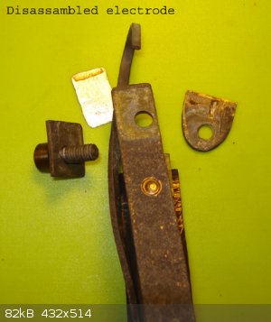
The Platinum bar is held in a bent piece of flat Ti by a Ti bolt. The cathode is held in place by bolting it to the anode current runner using a piece
of perspex as in insulator and spacer which is not visible in the picture. The bolt screws into a hole in the Ti which was threaded using a simple
threader.
The cathode in the vicinity of the anode is like a large blunt fishing hook. All Titanium including the bolt is grade one. Grades 2, 3 or 4 would be
ok. Grade 5 which contains Aluminium would likely corrode. The weigh of the piece of Platinum was weighed at 0.98 grams using a cheap, two decimal
point scales. I guess the scales was out by 0.02 grams?
The electrode was put to the test in a 'jam jar' cell containing dissolved sodium perchlorate (no chlorate or chloride) at one Amp for 15 days. Cell
temperature was around 30C and cell Voltage around 6 Volts. There were no noticeable problems or weight loss from the Platinum.
Brown deposit on Pt in the picture is from just after a run in a K perchlorate cell (see below) BTW.
New cell liquid which contained 424 grams sodium chlorate per litre of solution was added to the cell. No chloride. Cell volume was around 360ml
giving a total weight of sodium chlorate of around 153 grams. Current efficiency was around 75% when chlorate concentration was sensibly high. Five
days later chlorate concentration was measured at 0.5 grams per liter of solution. Platinum seems to be very good at rapidly reducing the chlorate
concentration to very low levels. No noticeable weight loss on Pt bar.
The anode makes around 44 grams of Na perchlorate from chlorate per day.
Another cell was started up with 500g/l Na chlorate and run for about 5.5 days. Chlorate at the end of run was measured at 0.08 grams per litre. There
was a smell of ozone from the cell at the end of run. No weight loss for the Platinum. The cell pH was not measured.
Potassium Perchlorate cell
Another cell run was performed this time using potassium chlorate as starting material at 168 grams per litre. The cell was kept warm at around 60C
using a hot plate as potassium chlorate is not very soluble when temperature is low. CE was lower than Na cells at around 50 to 60%. The formed
perchlorate was inclined to accumulate on the anode/cathode electrode and had to be brushed off two or three times.
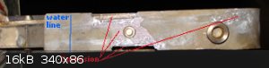
The cell was run to a point where there would be very little chlorate left in the cell liquor. Serious corrosion of the Titanium current runner going
to the Platinum bar occured just below the water line and this caused a deposit of grey Ti compound in the cell as the end of run approached.
Something to be watched if running K perchlorate cells but this problem did not occur on the next cell run. The actual cause of this corrosion is
unknown. See picture. BTW the Ti in question was not 'heat damaged' as in strontium cell below.
The Pt bar was not effected.
Another K cell was started up similar to the last one. 161 g/l K chlorate. Cell volume 372ml (60g K chlorate total). 60 hours later the cell was
stopped. Chlorate (in liquid) was around 1.6 grams per litre. Perchlorate was on the cell bottom. The was a brown deposit, see picture at top, on the
Pt which cold oxalic acid did not remove. The serial number on the Pt was getting hard to read and the surface of the Pt was getting a 'scrubbed'
look. There was no measurable weight loss on Pt bar with a cheap 2 decimal point scale.
Lithium Cell
Another cell was started using Lithium chloride as the starting material. The chloride was obtained from ceramic grade carbonate + HCl acid. 96.5
grams of Li chloride was dissolved into the cell giving around 261g/l in a 360cc volume. Current was one Amp using a constant current supply. A trace
of perchlorate showed up in the cell after some hours but only a trace. Twenty five days later perchlorate stared to form as the chloride level went
down to around 25 grams per litre. The chlorate run give around 50% CE. There was no attempt made to control pH. Chlorate making with a small anode
like this is very slow. Seven days later the cell was shut down. Chlorate level was measured at around 0.03 grams per litre and chloride level was
measured at less than 0.36 grams per litre. The cell contents was heated to around 150C for 6 hours to obtain the anhydrous perchlorate salt which (I
believe) in not possible to get without vacuum, so I probably had a mixture of the trihydrate and the anhydrous. Lithium perchlorate is the only
perchlorate with a known definite melting point. It does not decompose at its melting point.
Total weight of the perchlorate when it went solid was 217 grams. There was no weight loss on the Pt, it still weighed 0.98 grams.
Modified anode
It was decided to attempt to make the anode larger by hammerng the Pt bar and making it thinner. Pt leaf is made professional by placing the Pt
between layers of velum (light leather) and hammering. Two pieces of ordinary leather were obtained and an approx. 250g hammer with one side flat was
obtained and hammering began on a solid steel slab with the Pt between the two pieces of leather. The Pt flattened easily enough, its area was
increased to twice what is was. The area of the Pt was now 2.62cm squared per side. The anode/cathode assembley was simplified with the platinum now
being clamped between two flat pieces of Ti not unlike a pair of pincers with a very broad nose. The Ti bolt (grade one) together with a Ti washer,
the Ti with the threaded hole and the Ti current runner was used to do the clamping. Current was run at three Amps, which is a cd of 575 mA per square
cm, quite high. The same cathode was used as before. This 3 Amp anode will give around 130 grams sodium perchlorate (from chlorate) per day at 80% CE.
Strontium Cell
A Strontium chlorate/perchlorate cell was set up using Strontium chloride obtained by adding 276 grams pottery grade Sr carbonate to HCl. There was
approx. 2 grams insoluble stuff which was filtered out giving a clear solution of 296.3 grams chloride which is 1.87 moles (calculated from
carbonate). The purity of carbonate from the ceramics store is not known. It is best to leave some unreacted carbonate behind as metal impurities are
inclined to stay behind when this is done. A new 'jam jar' was obtained which contained 770ml solution giving 385 grams chloride per litre.
The anode was run at three Amps using a constant current supply for approx. 15 days. There was a problem with (I presume) insoluble strontium
hydroxide building up on the cathode which caused the cell voltage to rise and the current to go to zero. A stirrer bar about one inch long and a
magnetic stirrer at 800rmp was used to stop this happening. The temperature of the cell was around 38 centrigrade. pH was controlled be adding 1 or 2
cc of 12% HCl acid to the cell per day. This is very little acid compared to a sodium cell. pH was measured with a pH probe that was calibrated with a
buffer solution. Cell pH stayed around 6.8 for the chlorate stage and was at 1.8 at the run end. Acid was not added for the last few days.
The cell ran in the region of 38C. Cell voltage was inclined to move around a bit and varied from 5.5 to 7.5 Volts during the chlorate stage. The cell
voltage would start to rise immediately after the stirrer was stopped.
Perchlorate appeared in the cell soon after it was started. I did not measure how much but it was a significant amount judging by the addition of
methylene blue to a cell sample. 156 hours later (6.5 days) or 468 Amp-hours later perchlorate started to form in earnest. Chloride concentration was
around 200 g/l at this stage, seems very high.
Acid still needed to be added to cell for 5 more days to keep pH around 6.8. At this stage (day 12) there was a very 'mild' smell coming from the cell
which indicates the chlorate stage is over. Chloride concentration on day 12 was 44g/l with 7.7 Volts accross cell and a pH of 6.7.
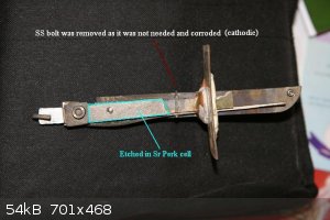
At the start of the run there was a ss bolt holding the cathode just above water line which had corroded and discoloured the solution. This
discolouration had now deposited onto the side of the jar leaving the liquid clear. It was decided to empty the container and wash the deposit off the
jar inside. This was done using a tooth brush and the anode/cathode was also washed and scrubbed with the tooth brush. When the cell was started again
with the stirrer as before the voltage accross the cell started to rise and the current went to zero. The rpm on the stirrer had to be increased to
1100rmp to keep cell current going at 8.6 volts. The voltage accross the cell reduced after a while and the stirrer was lowered back to 800rmp. I
think this problem was caused by the cell cooling down and when it got heated up again it ran in its usual fashion as something similar happened a few
days later. The solubility of the strontium hydroxide is greater in the warm cell and, I guess, builds up on the cathode less.
On day 12 the cell contents went grey as there was Titanium corrosion happening. It happened on the current runner as outlined in the picture. It was
not the usuall pitting corrosion that occures but a much larger area of the Ti was etched. pH of the cell was measured at 6.2. This piece of Ti (Grade
one) was subjected to high heat sometime in its past that made it very brittle. When placed in a vice and struck with a hammer it would snap as
opposed to bend. Perhaps its corrosion resistance was compromised? The other pieces of Ti (not high heat damaged) did not corrode. The cell at this
point had sizable concentrations of both chloride and chlorate which is a potential region for Pt to erode, and perhaps Ti too! (as described
elsewhere).
The cell was stopped, contents filtered and the anode/cathode washed and the cell started again. There was no more serious corrosion problems. The
cell had to be warmed up using the hot plate to stop the voltage rising too much and causing the current to go to zero even at 1100 rpm (up from 800).
The cell ran OK but it was noticed that the rpm of the stirrer had to be kept at the increased rate of 1100 rmp to stop the voltage from rising too
much accross the cell. This problem stopped when the cell warmed up (hydroxide has greater solubility?). The actual junction between the Ti and Pt was
not the problem because when anode and cathode where shorted together the current ran at 3 Amps.
Day 13, chlorate was measured at 161 g/l. Day 14, chlorate was measured at 56g/l and the chloride was at 12g/l.
The solution was getting a bit cloudy (corrosion?) with the pH at 1.8. The voltage accross the cell was 8 volts with the cell at 38C and decreased to
6.4 volts When the cell was warmed to 56C using the hot plate (cc of 3 Amps and 1100 rpm). The end of day 15 saw chloride at 4.7g/l and chlorate at
0.3g/l. The chloride seems to be higher that the chlorate? There is small amount of white Ti corrosion compound visible between the Ti and the perspex
piece holding anode and cathode apart but nothing too serious.
The Pt piece was removed and weight at 0.97 grams, down from 0.98 grams. Some Pt erosion it would seem. It is hard to say as the scales I have are
just too crude for the job. A three or four place scale would be required. When the scales was taken to a warmer place it was inclined to read 0.98
again.
The cell was let settle for three days to allow cloudyness to deposit on cell bottom. Clear liquid was decanted off and the rest filtered. Liquid was
dried off by placing the cell contents in a flat glass tray in an oven and heating to 170C for about 24 hours. It was very difficult to get rid of the
water. A total of 474 grams (1.65 moles) of Sr perchlorate was obtained, there should be 535g (1.87 moles)). Some grams product would have been lost
when doing titrations etc. The amount of product does not correspond to the amount of starting Sr carbonate. There is approx. 60 grams missing? I have
no idea where it could have gone or what error was made. Total Amp-hours into cell was 1049Ah which is 39.14 moles of electrons. Having 1.65 moles of
product gives 1.65 x 2 x 8 = 14.952 moles of electrons needed, giving a current efficiency of 56.6 percent.
A larger cathode could be used to stop the low solubiltiy of strontium hydroxide causing cell voltage problems.
To end Ti corrosion problems a more 'valve' valve metal could be used like Niobium. This will cost more but if the cell is being stirred the anode
only needs to go below the surface of the electrolyte and therefor you would need very little valve metal.
Barium Cell
Note that barium is toxic. Barium perchlorate can be useful for making perchloric acid and other perchlorate salts as the sulphate is insoluble. To
make perchloric acid you just add sulphuric acid and remove insoluble Barium sulphate.
A barium chlorate/perchlorate cell was started up. Chloride was obtained from 500g ceramics store carbonate + HCl acid. Not all of the carbonate
would dissolve with perhaps 10% left over. The mixture was left overnight to get as much to dissolve as as possible. Perhaps heating might have
helped? The purity of the carbonate is unknown. HCl was 12% concrete cleaner (no additives). It is best to leave some unreacted carbonate in the
system as this has the effect of removing metal impurities.
The cell and anode/cathode was the same as the last cell above. Current was 3 Amps, constant current supply, with V at 5.76 and temperature at 38C.
Stirring was not required but was used anyways. The solubility of barium hydroxide is higher that strontium hydroxide. pH control was attempted and
about 2cc 12% HCl was added per day to keep pH around 6.2 during chlorate stage. The pH of the cell at shut down was around 2. The cell was cloudy
from the start due to some carbonate that was not properly removed and turned a nasty brown colour after a few days. The cell was shut down for two
days to allow the cloudyness to settle and the clear liquid was decanted off.
Cell restarted and was run until chlorate concentration was 0.76g/l. There was a black discolouration in the cell at the end of the run together
(after black stuff had settles) with a very slight haze of gray (titanium erosion product?). The cell was let settle for about a week as it took that
long for the gray to settle to the bottom and the clear liquid was decanted off. The solution was placed in a flat glass baking tray in an oven and
dried at 130C for about six hours. It was much easier to dry than the Sr perchlorate above. Total weight of product was 533g or 1.585 moles.
Total Amp-hours into cell was 1191Ah or 44.44 moles of electrons.
The current efficiency (ce) was 57%. Final weight of Platinum bar was now 0.95, down from 0.97 grams so there was some loss of Platinum. Thats 37.5
grams of Platinum per ton of perchlorate produced. I have seen figures for platinum lost (sodium perchlorate production) of 2 to 7 grams per ton.
Sodium Perchlorate cell using 'poor' starting solution
The jam jar cell was started up again using a solution containing 95g/l sodium chloride and 496g/l sodium chlorate and around 600ml. This is not a
sensible starting solution for Platinum anode perchlorate cells as chloride causes anode erosion. This cell could be called a chlorate cell for the
first day or two I suppose. Stirring was not used as the anode was close to the jar bottom and bubbles kept all of the solution moving.
No pH control was attempted. The cell was run at 3 Amps for 3 days and chlorate level was above 15g/l. The pH of the cell was measured at around day 4
and found to be high at around 9. Cell contents were titrated for chlorate level on the seventh day of operation and found to be 5.14g/l Twenty four
hours later the chlorate concentration was below 1g/l. The pH at this stage was measure with a high quality probe at a value of 11.5 but you can
measure the pH OK using pH paper (only when cells have high pH it would seem, see cell No. 2 below) as there is no bleaching effect as you have in a
chlorate cell due to the presence of hypochlorite (bleach!).
Cell contents was evaporated and dried at around 150C for some hours. Total product (presume anhydrous) was 446grams perchlorate. Total Amp-hours into
cell was 576Ah AFAICR.
Two more sodium cells
No. 1
Two cells were run using the same starting solution as above, 97g/l chloride and 496g/l chlorate. Cells contained 770ml liquid. Current was 3 Amps.
Stirring was used. Chloride was not monitored except to note what the starting concentration was. No pH control was used for the first cell. (Cell No.
2 had acid added)
pH when the chloride became low (cell became a perchlorate cell) was around 9. At 360g/l chlorate, pH was 9.5. Current efficiency was measured at 94%
when chlorate concentration was between 360 and 188 grams per litre.
When chlorate concentration was between 188 and 53g/l CE was around 70% with pH around 9.
When chlorate concentration was between 53 and 2.3g/l CE was around 24.5% with pH around 9.6.
Cell was stopped around 14 hours later with chlorate concentration around 0.11g/l.
The cell was run for a total of 7 days.
No. 2
The next cell was the same as above but 12% HCl acid was added to keep pH at around 7 or so for the first few days (chlorate stage). pH control was a
bit hap-hazzard. Stirring was used. The pH of the cell was measure at the start and was around 9.8. 2cc acid was added and cell went to pH 7. A few
hours later the cell was at pH 9 and it took 19cc of acid to take the pH to 6.8. The next day 7cc of acid was added to keep cell around a pH of 6.8.
Next day 7cc acid added. Next day 4cc added very early in the day with no more acid additions needed to keep pH around 6.8. pH drifted down slightly
later in the day and chlorate concentration was measured at 400g/l. Later in the day chlorate concentration was at 349g/l. The cell had now ran for 78
hours, 234 Amper-hours had passed in.
When the chlorate concentration was betweeen 349 and 184g/l the CE was 86% with pH around 6.8.
When chlorate concentration was between 184 and 8.8g/l the CE was close to 100% with pH around 4.7. (suspiciously high CE!)
Twelve hours later the chlorate concentration was 0.53g/l with pH now at 1.7. You cannot use pH paper for to measure this low pH for
some reason or other. It gives a false reading of neutral.
This cell had run for 5.5 days to take chlorate concentration to a low level. The last cell ran for six days to take chlorate concentration to a low
level.
There was no sign of titanium erosion in the last three cells. All liquor at end of runs was clear.
The Platinium bar now weighed in at 0.91 grams, down from 0.95 three cells/batches ago. That's approx. three batches of 440 grams sodium perchlorate
made from a 'not-to-be-recommended' starting solution taken all the way to very low chlorate levels. This equated to 30.3 grams Pt per ton of Na Perk.
produced. Ferocious erosion compared to commercial production cells. The starting solution contained chloride. Making perchlorate with chloride in the
cell is erosive to platinum according to various sources. Also keeping chlorate concentration high in the cell will give greater CE and probably
reduce Pt wear. Using the Pt to reduce the chlorate concentration to very low levels (chlorate scavenging) as opposed to letting the Na Perk.
crystallize out of solution (my adding chlorate to cell as the cell progresses) saves lots of work and is easy to do.
|
|
|
yobbo II
National Hazard
Posts: 709
Registered: 28-3-2016
Member Is Offline
Mood: No Mood
|
|
Attempted doing the same using tungsten TIG welding electrodes and they work OK.
Can anyone tell me what might be the blue color in the second cell?
Using a Tungsten current runner
Since Titanium is not exactly OTC it was decided to see if Tungsten could be substituted for the Titanium as W is a 'valve' metal similar to Ti, Nb
etc. Two TIG welding electrodes of approx. 3.5mm dia. and 150mm long were to hand, the exact type of electrode was unknown (if they contained Thorium,
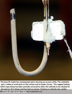
Cerium etc). Thinner electrodes would probably do just as well. The two rods were placed side by side and bound together using plumbers teflon tape.
The Pt plate (hammered bar) was slid between the rods and the bottom ends of the rods were then squeezed together tightly with a pair of small
vice-grips (locking plyers) and some more teflon tape wound around the bottom ends of the rods and tied securely. A 625 Inconel welding rod was used
as the cathode as it was to hand. An ordinary piece of stainless steel would do just as well.
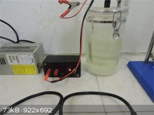
The anode was placed into a cell (similar to the last two cells) of 770ml containing a solution of 95g/l sodium chloride and 496g/l sodium chlorate.
Current was three amps. No pH control was attempted. Voltage accross the cell was 6.6V.
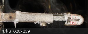
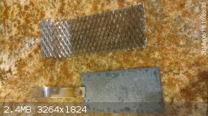
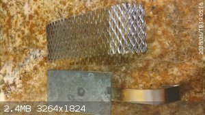
After 62 hours of operation the electrode was examined and it was noticed that the tungsten was being etched away. The rods are much thinner as shown
in the small picture. There was a yellow compound being deposited on the platinum (WO3, probably). The pH of the solution was around 7.
There was a black deposit on the Inconel cathode above the water line. I have seen this before in perchlorate cells using Nickle cathodes.
Another attempt
Some pure tungsten TIG rods (green tiped) were obtained and a new anode was constructed. A solution of pure sodium chlorate consisting of 230 grams in
770ml, 299g/l, of solution was prepared. There was no chloride present. The anode was similar to the last one except the TIG rods were thinner, at
about 2mm dia. Current in the cell was reduced to 2 amps, down from 3. The pH at the start was 5.3. This increased to 7.4 after 22 hours. There was
small deposits of yellow stuff appearing on the platinum but it was difficult to see any W corrosion. It was decided to lower the cell pH by adding
perchloric acid (around 50%), 3ml taking pH to 1.7 . The yellow deposit disappeared off the platinum in about an hour or so. A few hours later the pH
was 0.5 and it stayed at this value for the rest of the time that the cell ran. A brown discolouration appeared in the cell from the start and it was
assumed this came from impurities in the starting material.
After seventy one hours of running the chlorate concentration was 4.4g/l. The cell was let run for seven more hours and during this time the solution
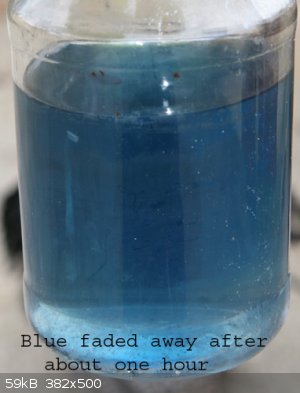
went completely clear (brown discolouration either deposited on the cell bottom or onto the teflon tape, see picture of electrode). and strangely
enough a blue colour appeared. There was also a black deposit on the Inconel cathode.
Cell was run for 6 more hours and closed down. Six hours later the blue colour had gone!
Cell was started up again and the blue colour started to return after 14 hours of running. Five or so hours later it had fully returned (see picture).
The colour equivalent was similar to adding about 8 grams copper sulphate pentahydrate to one litre of water, but the actual colour was a more darker,
more 'purple' blue. The cell was run for another 21 hours and stopped. One hour later the blue colour was gone, the solution was now clear again. I
presume the blue is some Nickle compound???
First Tungsten-runner cell (above) revisited
The saved contents of the cell that I had started with above, (with the thicker Tungsten current runners at 3 Ampers (Tungsten had corroded)), was
placed in the cell for to see of there was any W corrosion under a different pH. The pH of the cell contents last time (when W corroded) had been
running at around 7.0 . Four cc's of perchloric acid (around 50%) was added to lower pH. A white ppt appeared. pH went to 4.0, 5cc more added (more
white ppt) and pH went to 1.6, 10cc more took pH to 1.1 . The solution was now milkey white.
The white ppt may be some Tungsten compound as the cell contents must have some W dissolved (in some form or other) from its time in the first W cell
above where corrosion of the W welding electrodes took place. The new pure W (green tiped electrodes) current runners were use here BTW.
Cell contents was 25g/l chloride and 380g/l chlorate. The cell was stirred.
Quite a smell of Chlorine came from the cell, you could actually see the chlorine (I think) sitting on top of the liquid under the lid as you could
actually see it blowing away when the lid was lifted and you blew at it! Perhaps there was some ClO2 as well?
Current was 2.05A, Volts was 6.2, Temperature was 28C, cell volume around 790cc.
pH after about 2 hours was 0.6 . pH paper can be used to read pH (Watman Type CF) though I am using a pH meter.
The pH was kept low in a rather hap-hazzard way using 50% (approx.) perchloric acid. The whole problem of trying to keep the pH low is made difficult
by the fact that the cell contains chloride. It is ALWAYS best to keep chloride out of perchlorate cells.
Thirty six cc of acid were used in lots of 4cc to 10cc to keep pH around 1.5 for the next 2 days. Sometimes pH managed to get up to 6.0 . There was
quite a smell of chlorine after acid was added. The white milkey ppt that was in the cell was inclined to deposit on the Platinum and was brushed off
a few times. The black coating that was on the cathode went away. After two days chloride was at around 2g/l and chlorate was at 162g/l. No more acid
additions were needed as the cell pH was around 1.3 after the last addition. It slowly rose up to and was about 4.0 at the end of the cell run.
The CE over the next 24 hours was close to 100%.
Some chlorine would have been lost from the system, some added via the perchloric acid. The cell liquid was still not clear, some what milkey
appearance. Twenty four hours later the chlorate concentration was 0.4g/l with the liquor getting clearer. There was a white deposit coming onto the
cathode. It's as if the ppt that the perchloric acid additions caused had migrated from the solution to the cathode. The anode was clear at this time.
Twenty four hours later the cell was shut down. There was no visible erosion to the W electrodes or that could be detected using a micrometer. The
rods are very shiney as if the W oxide coating is transparent. A white deposit appeared on the anode during the last 24 hours, perhaps a W compound
from the last run? The Platinum was cleaned and weighed at 0.91g (no loss).
Using a Valve metal works well for platinum (and MMO too). It allows all the surface area of the more expensive and harder-to-get item to be utlized
doing something most useful.
It is hard to say if the tungsten erosion above was caused by the presence of chloride, the high pH, the type (purity) of the tungsten electrode or
higher current density (50% higher) or a combination of all four. IMO pH has a large effect as there was a yellow deposit appearing on the anode in
the second W cell above when the ph was around 7 and this dissolved away without no more erosion to W happened as the cells were run. I am not 100%
sure if the yellow deposit was coming from eroded W?
Other valve metals could be used. Tantalum and Hf have better resistance to reverse voltages and therefor will have less risk of getting etched or
corroded. Grade 11 Ti (if you can get it) will have greater corrosion resistance. It contains Pd. You will only need a small amount of Valve metal if
you keep the anode close to the surface of the cell and use stirring. You could place the cathode at the bottom and the hydrogen would probably keep
the cell agigated.
It is impossible to set the pH of a perchlorate cell low if it contains chloride without excessive chlorine gas being generated. As more chloride
excapes you need more acid. If using HCl acid this is a vicious circle as you are adding chloride. With perchloric acid it's not much better and you
will need to make the acid first. KEEP CHLORIDE OUT OF PERCHLORATE CELLS. Only allow a few grams per litre, or less, to be present.
To quote: "In effect, platinum forms an equilibrium or quasi equilibrium state when evolving chlorine, and a rather different state for oxygen
evolution. During co-joint oxygen and chlorine evolution, which occurs in dilute brine, there is interference in the formation of surface layers and
this leads to accentuated metal dissolution."
(Platinum Metals Rev., 1998, 42, (l), 27-33)
Something similar is probably going to happen in a perchlorate cell with some chloride in it. The above is in relation to platinum. Perhaps valve
metals come under pressure and are more inclined to corrode when used as the anode current runner if chloride is present.
You could use an additive like sodium dichromate as it is supposed to help protect Pt and perhaps the Valve metal current runners too.
Be aware of starting material purity. It was surprising all the colours, ppt's and anode/cathode deposits that occcured when running the cells.
Avoid using nickle cathodes.
Nickle containing cathodes seem to give black corrosion products above and sometimes below the water line. Better to use stainless steel or Titanium.
|
|
|
markx
National Hazard
Posts: 645
Registered: 7-8-2003
Location: Northern kingdom
Member Is Offline
Mood: Very Jolly
|
|
I'm having a suspicion that the blue colour might originate from a form of tungstate (or related compound formed in cell liquor).
I see a very similar discoloration when I electrolyse ammonium molybdate solution at higher current densities to create colored interference layers on
stainless steel. The blue appears at the surface of electrodes and dissipates into the solution where it disappears after a few hours. At first I
thought this might be caused by dissolution of components from the stainless electrode alloy, but the same appeared also when Ti electrodes were used
in the molybdate solution. There is little chance that titanium dissolved under these conditions so I'm inclined to thinking that this is still
connected to Mo compounds....as you used a tungsten current lead, there might be a similar situation happening in your cell conditions.
[Edited on 3-4-2018 by markx]
Exact science is a figment of imagination.......
|
|
|
Simoski
Hazard to Self
Posts: 82
Registered: 24-12-2017
Location: Johannesburg South Africa
Member Is Offline
Mood: No Mood
|
|
New Anode Material to Try
Hi
I was watching YouTube a while back and the guy was doing a video on lanthanum. What struck me as interesting was lanthanum hexaboride for use as an
anode. It is a ceramic, will not oxidize and is extremely conductive. It should make one of the best perchlorate anodes ever, here an except from
Wikipedia...
Lanthanum hexaboride (LaB6, also called lanthanum boride and LaB) is an inorganic chemical, a boride of lanthanum. It is a refractory ceramic material
that has a melting point of 2210 °C, and is insoluble in water and hydrochloric acid. It has a low work function and one of the highest electron
emissivities known...
Do you think it will produce perchlorate?
|
|
|
yobbo II
National Hazard
Posts: 709
Registered: 28-3-2016
Member Is Offline
Mood: No Mood
|
|
Two sources state that it is not compatible with strong oxidizing environments/agents. Since an anode IS a strong oxidizing agent I think that would
rule it out.
https://www.americanelements.com/lanthanum-hexaboride-12008-...
Lanthanum Hexaboride is highly insoluble in water and converts to the oxide when heated (calcined). Borides are hard, high-melting materials with
metal-like conductivity. They are stable to nonoxidizing acids but break down in strong oxidizing agents and strong alkalis. Borides are used in
semiconductors, superconductors, diamagnetic, paramagnetic, ferromagnetic, anti-ferromagnetic, turbine blades, and rocket nozzles. Borides have
recently been discovered to be superconductive and ultra-incompressible. Lanthanum Boride is generally immediately available in most volumes. High
purity, submicron andHigh Purity (99.999%) Lanthanum Boride Sputtering Target nanopowder forms may be considered. American Elements produces to many
standard grades when applicable, including Mil Spec (military grade); ACS, Reagent and Technical Grade; Food, Agricultural and Pharmaceutical Grade;
Optical Grade, USP and EP/BP (European Pharmacopeia/British Pharmacopeia) and follows applicable ASTM testing standards. Additional technical,
research and safety (MSDS) information is available as is a Reference Calculator for converting relevant units of measurement.
https://www.alfa.com/en/catalog/040325/
Notes
Incompatible with strong oxidizing agents.
You can look for a price here but I would not imagine it will be cheaper that Pt.
https://www.lesker.com/newweb/deposition_materials/depositio...
and here
http://www.samaterials.com/lab6/1413-lanthanum-hexaboride-la...
More info</a></li></ul><div class="sheets align_justify" id="more_info_sheets"><div class="rte"
id="idTab1"><p>Lanthanum Hexaboride (LaB6, also called lanthanum boride and LaB6) is an inorganic chemical. With melting point 2528 K, LaB6
is a refractory ceramic material, which is insoluble in water or hydrochloric acid and very stable in vacuum. Stoichiometric samples are colored
intense purple-violet, while boron-rich ones (above LaB6.07) are blue. Ion bombardment changes its color from purple to emerald green. LaB6 is a
superconductor with a relatively low transition temperature of 0.45
K.</p><p><strong>Specification:</strong></p><table border="0" cellpadding="0" cellspacing="0" style="width:
684px;"><tbody><tr><td width="160"><p align="left"><strong>Product</strong></p></td><td
width="168"><p align="left">Lanthanum Hexaboride</p></td><td width="191"><p
align="left"><strong>Structure</strong></p></td><td width="165"><p
align="left">Polycrystalline</p></td></tr><tr><td width="160"><p
align="left"><strong>Symbol</strong></p></td><td width="168"><p align="left">LaB6</p></td><td
width="191"><p align="left"><strong>Thermal Conductive </strong></p></td><td width="165"><p
align="left">47 W/mK (20℃)</p></td></tr><tr><td width="160"><p align="left"><strong>Cas
No.</strong></p></td><td width="168"><p align="left">12008-21-8</p></td><td width="191"><p
align="left"><strong>Thermal Expansion </strong> <strong></strong></p></td><td width="165"><p
align="left">6.2 10<sup>-6</sup>K<sup>-1</sup> (20-900℃)</p></td></tr><tr><td
width="160"><p align="left"><strong>Atomic Mass</strong></p></td><td width="168"><p align="left">203.78
g/mol</p></td><td width="191"><p align="left"><strong>Electrical
Resistance</strong> <strong></strong></p></td><td width="165"><p align="left">ca.15 μΩ cm
(20℃)</p></td></tr><tr><td width="160"><p align="left"><strong>Density
</strong></p></td><td width="168"><p align="left">4.72 g/cm<sup>3</sup></p></td><td
width="191"><p align="left"><strong>Electrical Conductive</strong></p></td><td width="165"><p
align="left">6.65x10<sup>4 </sup>S/cm (20℃)</p></td></tr><tr><td width="160"><p
align="left"><strong>Melting Point</strong></p></td><td width="168"><p align="left">2528
K</p></td><td width="191"><p align="left"><strong>Currenty Denstiy </strong></p></td><td
width="165"><p align="left">150 A/cm2 (1950℃)</p></td></tr><tr><td width="160"><p
align="left"><strong>Hardness</strong></p></td><td width="168"><p align="left">87.5
RA</p></td><td width="191"><p align="left"><strong>Electron Emissivity</strong></p></td><td
width="165"><p align="left">2.6 eV</p></td></tr><tr><td width="160"><p align="left"><strong>Flexure
Strength (σ)</strong></p></td><td width="168"><p align="left">200 Mpa</p></td><td width="191"><p
align="left"><strong>Fracture toughness (Kic)</strong></p></td><td width="165"><p align="left">3.0
MN/m<sup>3</sup>/2</p></td></tr></tbody></table>
Yob
|
|
|
Sulaiman
International Hazard
Posts: 3555
Registered: 8-2-2015
Location: 3rd rock from the sun
Member Is Offline
|
|
yobbo II
It seems to me that you have been operating your cells with a significant surface area of titanium exposed to the electrolyte(s),
comparable to the platinum surface area,
yet there seems to have been only moderate corrosion of the titanium.
If this observation is correct, why not just use titanium for the anode ?
(I've not made a chlorate or perchlorate cell yet, but it's on the list.
CAUTION : Hobby Chemist, not Professional or even Amateur
|
|
|
markx
National Hazard
Posts: 645
Registered: 7-8-2003
Location: Northern kingdom
Member Is Offline
Mood: Very Jolly
|
|
Quote: Originally posted by Sulaiman  | It seems to me that you have been operating your cells with a significant surface area of titanium exposed to the electrolyte(s),
comparable to the platinum surface area,
yet there seems to have been only moderate corrosion of the titanium.
If this observation is correct, why not just use titanium for the anode ?
(I've not made a chlorate or perchlorate cell yet, but it's on the list. |
Titanium is what is called a "valve metal"...it passivates under anodic conditions and becomes covered by nonconductive oxide layer, hence it also
resists corrosion very successfully. Ti can not be used as the anode on its own, only as a substrate material and current lead.
Exact science is a figment of imagination.......
|
|
|
yobbo II
National Hazard
Posts: 709
Registered: 28-3-2016
Member Is Offline
Mood: No Mood
|
|
The titanium only corroded when used in a potassium perchlorate cell and in a strontium perchlorate cell. In the case of the K Perk cell, the ionic
strength (total dissolved solids) of a K perchlorate cell gets low and this (IMO) stresses the titanium oxide and you get corrosion.
In the case of the Sr Perk cell I was using a piece of 'dodgy' titanium that had been subject to high heat some time in the past. This may have
effected its ability to withstand corrosion (poorer oxide coat) or perhaps Sr Perk cells have a greater negative effect on the protective Ti oxide
layer.
The whole point of using a valve metal as the current runner to transport current to the platinum anode (it's the Pt that is the anode, not the
Titanium) is that you can purchase a small piece of platinum and use ALL of it to do useful work.
Platinum wire is inclined to be very expensive and using the (usually fairly thin) wire to transport all the current to the Pt below the surface of
the liquid leaves the wire very hot (the piece above the liquid surface) and liable to corrode or even melt and break off.
|
|
|
stamasd
Hazard to Others
Posts: 133
Registered: 24-5-2018
Location: in the crosshairs
Member Is Offline
Mood: moody
|
|
Let me start documenting here my experiments in making potassium perchlorate from potassium chlorate using MnO2 anodes.
I made my anode from a 5*10cm plate of Ti (0.5mm thick) cut from a larger sheet of 10*10cm; the other part of the sheet was cut in strips and the
strips used to make the cathode for the cell as well as the connecting terminal for the anode. One strip of 1.5*10cm became the cathode, another strip
of the same size was spot-welded to the anode after coating using a spot welder I have (used normally for thin nickel strips, but on the highest
energy setting works well for thin titanium too).
For the coating I used thermal decomposition of cobalt nitrate and manganese nitrate. Both reagents were made from pottery-grade cobalt and manganese
carbonates. The cobalt nitrate appeared pure enough, the manganese one had iron contamination and was further purified using the method from
NurdRage's old video (partial conversion to hydroxides, overnight oxidation etc). I did 4 applications of cobalt to each side of the anode (after
thoroughly degreasing, mechanical scouring and chemical etching in dilute nitric acid) followed by 6 applications of manganese to each side. Thorough
rubbing with a wet paper towel after each application to remove any loose adhering oxides. The anode was then dried and then again rubbed thoroughly
with moist towel until no more material rubbed off of it mechanically.
A preconditioning of the anode was done by running in a 10% NaCl solution at approx 3A for a few hours. The solution turned a light pink, but no
change in the physical appearance of the anode was noted, and no particles of MnO2 appeared to shear off it. The electrolyte remained clear.
For the actual experiment I used KClO3 previously produced in a Ti/MMO cell and purified. 122g KClO3 (roughly 1 mol) was dissolved in warm distilled
water to a final volume of 950ml; that was enough to keep all KClO3 dissolved at 40 degrees C. I ran the cell at an average of 3A (the current varied
during the electrolysis because of evaporation and relative positioning of the electrodes, but the 3A is IMHO a good estimate of the average; min
current was 2.3A, max current 4.4A). No pH control was done. A total of 200ml water was added during the run. The time was 33.5h, and final volume of
the electrolyte was just above 800ml. A layer of acicular crystals was at the bottom of the cell (about 2cm thick in a 1L beaker), and a substantial
amount of the same crystals was floating at the top but were easily dislodged by shaking and sank to the bottom. The crystals were mixed with a small
amount of dirty brown powdery residue, likely MnO2. During the electrolysis, the color of the electrolyte changed from colorless to a light pink
immediately after the start, the pink color intensified in the first 3-4h to a maximum pink-purple then began to fade very slowly to a final light
pink. Too bad I didn't think of taking pictures of each stage.
Total current used was approx 100Ah; theoretical needed at 100% current efficiency for 1mol KClO3->KClO4 conversion is 2*26.8=53.6AH so I used 1.86
times that. This was done deliberately as I expect the current efficiency to be 50-60%.
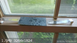
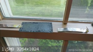
The anode appearance at the end was pretty much unchanged from the start. The cathode was covered with a dark brown sludge, most of which was easily
rubbed off with a paper towel, and anything remaining after that came off with light scouring with a copper sponge.
My purification strategy for the product is as follows:
1. removal of the dark brown precipitate: I avoided the need for a hot filtration (which has been problematic in the past) by heating the electrolyte
until all crystals dissolved, allowed it to stand hot in the beaker and doing repeated decanting with short blasts in the microwave in between to keep
the solution hot. I achieved substantial removal of the precipitate this way. The solution was allowed to cool to RT and a layer of acicular crystals
formed again at the bottom. Will attach picture below.
2. From this point on, I will do the following (still to come). I made the assumption that no more than 50% of the chlorate is still in the
electrolyte, unconverted. That's 61g from the 122g initially added. The minimum amount of solution that will keep that dissolved at 25C is 750ml,
convenient since I have 800ml now. I hope that the crystals at the bottom are mostly KClO4, with only trace KClO3. After allowed to mature for 1 day,
the crystals will be filtered out, quickly rinsed with water and dried. I will not further process the remaining electrolyte now, but will keep it to
use as base for further electrolysis.
3. Will need to test the crystals for chlorate. I don't have now any of the usual reagents for the tests, nor to funds to purchase them. When I can I
will get some indigo carmine and use that method. For removal of chlorate I plan on using the metabisulfite method, which I have plenty of (I'm a
homebrewer and use that for wine). After further recrystallization and testing for chlorate I will calculate the yield. That will take a while though
as I have to be at work all of this weekend and all of next week.
So far so good, the anode has degraded much less than I expected, and the contamination by MnO2 and KMnO4 also less problematic than I thought it
would be. But again, I will have to get a yield calculated.
Below pictures of the anode and cathode after the run, and of the crystals formed after removal of the precipitate.
[Edited on 16-6-2018 by stamasd]
|
|
|
stamasd
Hazard to Others
Posts: 133
Registered: 24-5-2018
Location: in the crosshairs
Member Is Offline
Mood: moody
|
|
Update: a rough weighing of the now almost completely dry crystals showed 57g. Even accounting for the estimated 12g or so of perchlorate still in the
electrolyte, that still makes a terrible yield.
|
|
|
stamasd
Hazard to Others
Posts: 133
Registered: 24-5-2018
Location: in the crosshairs
Member Is Offline
Mood: moody
|
|
So I'm sitting here during a break at work and planning the next experiment. Here's a quick overview, and a question.
1. reuse the 800ml electrolyte from previous experiment to benefit from the residual chlorate and perchlorate already in it.
2. add another mol of KClO3, heat until it dissolves, adjust volume to 1000ml, let cool, pour off anything that crystallizes.
3. Make a better cathode; most of the problems I've had in the previous run were due to the short cathode. Will spot-weld another strip of titanium to
the existing one.
4. ?? (see below)
5. run at 3A, 48h which should be 2.68x the current needed at a theoretical 100%CE.
6. see what yields.
The ?? at #4 above pertains to using additives in the cell. Candidates would be NaF or K2Cr2O7. I've read that NaF is not recommended for any cells
using Ti-substrate anodes. This leaves the dichromate, but either my search-fu isn't working or nobody has used it in a cell with MnO2 anodes.
Does anyone have data on K2Cr2O7 used in Ti/MnO2 cells?
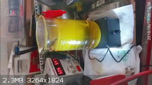
(edit) I have started the 2nd experiment thus:
800 ml electrolyte from previous expt; added 123g KClO3 and heated, added water to 1100ml (not everything dissolved, there are about 10-20g crystals
on bottom)
Added 2.6g Na2Cr2O7 (turns out I don't have K2Cr2O7). Changed cathode to 165*50mm Ti mesh (it's about 2/3 immersed in electrolyte). Put magnetic bar
in and started stirring on med.
Current limited to 5A. Voltage is 5.7V.
Start time is 6/18/18 at 7PM
24h=24*5=120Ah; that is 120/53.6=2.23x the theoretical.
Will stop after 24h and see what results.
Will be hard to appreciate any permanganate formation because the color is bright yellow from the dichromate.
New cathode picture below.
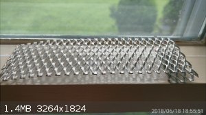
Also picture of the cell at 12h. The stirbar was overwhelmed by the crystals at the bottom and I couldn't get the stirring restarted.
[Edited on 19-6-2018 by stamasd]
|
|
|
stamasd
Hazard to Others
Posts: 133
Registered: 24-5-2018
Location: in the crosshairs
Member Is Offline
Mood: moody
|
|
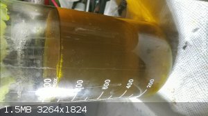
After 24h and 120Ah the color turned to a muddy yellow-green. I guess a lot of Cr3+ was formed. Picture below. The cathode got a grey tint that
doesn't come off with scrubbing. The anode appears mostly OK even though the layer of oxides appears somehow more translucent than before. Still
functions well as an anode. The current just before shutdown was 5A, voltage had risen to 6.35V.
I've put the beaker in a fridge; I won't have time to process what's inside for several days.
[Edited on 20-6-2018 by stamasd]
|
|
|
NedsHead
Hazard to Others
Posts: 409
Registered: 9-12-2014
Location: South Australia
Member Is Offline
Mood: No Mood
|
|
I found some Pt plated titanium for sale on eBay from a German seller and thought I would post it here for anyone that might be interested, I can't
vouch for them myself but they do have a good seller rating and have some other anodes at a good price.
https://www.ebay.com.au/itm/Platin-Elektrode-Platiniertes-Ti...
|
|
|
hissingnoise
International Hazard
Posts: 3940
Registered: 26-12-2002
Member Is Offline
Mood: Pulverulescent!
|
|
70mm of plated anode seems a bit, er, on the short side...?
|
|
|
NedsHead
Hazard to Others
Posts: 409
Registered: 9-12-2014
Location: South Australia
Member Is Offline
Mood: No Mood
|
|
it's 80mm, and it might be useful to someone
|
|
|
JScott
Hazard to Self
Posts: 51
Registered: 23-8-2018
Member Is Offline
|
|
I promise, better pictures next time. I didn't think anyone would see them when I took em ;-)
I followed NerdRage's video and his advise regarding platinum anodes. I had initially run this with a dc/dc converter that offered voltage and current
control but found it was horribly inefficient. I will rethink the converter for the next run.
Straight from the five volt pin of my little breakout box it used no more than 2-3 amps over the few days I ran it. I am away from notes tonight, but
tomorrow will post more info regarding yield over time.
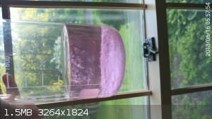
My wife found these containers at Wally world. I've seen others online have adopted them for cells also.
The anodes (platinum plated titanium) we purchased directly from the link NerdRage provided. He (TMC if I remember correctly) is still selling them on
Ebay and Amazon. It held up very well over the seven days I ran this cell. My cathode was a titanium strip purchased from the same seller. It also
held up very well. Other than discoloration, there is little evidence they have even been used. Some slight pitting where both entered the solution.
The digest from my notes I promised yesterday:
The cell held 1300ml. The solution was distilled water saturated with chloride (1.16 grams/ml). I found it difficult at the labs ambient temperature
(22.5C in the hood on this day) to keep this much chloride in solution. In my first run a good deal of chloride fell out of solution, perhaps as the
lab cooled at night. I mistaken believed at first I had a banner overnight success only realize it wasn't cholrate collected at the bottom of the
cell.
The cell seemed, through evaporation, to loose about a ml a day. I topped it off each day (with saturated solution) and checked it's saturation
levels. It seems by adding that milliliter of saturated solution each day, I kept the cell well feed. The temperature never exceeded 52.7C. The
voltage was between 3.2 and 3.5 volts and I the cell drew 2-3 amps. I did not account for cell Ph, but will remember to do that next run.
I collected 192.7 grams in seven days.
[Edited on 8-30-2018 by JScott]
[Edited on 8-31-2018 by JScott]
|
|
|
Simoski
Hazard to Self
Posts: 82
Registered: 24-12-2017
Location: Johannesburg South Africa
Member Is Offline
Mood: No Mood
|
|
Here are some thoughts on anodes, I have been making chlorates for a few years now and have some insight I would like to share.
Initially I used carbon gouging rods with 316l ss cathodes, I would build arrays of like 20 of them ( 20 rods ) and ran the electricity in and out
from the top. This is, as far as I have seen, a very common practice and quite logical. However what I found was that the carbon rods corroded right
at the top of the cell. This too makes sense because the electrons enter the cell at the cathodes and take the path of least resistance through the
electrolyte to the anode and exit. The current density at the top of the cell was very high and was causing the corrosion . Later versions ran
electrons in at the bottom of the cell and out at the top and this extended the life of the electrode assembly.
Later I swapped to mmo and still use this principle today, I run the current down to the bottom of the cell via the cathode but cover the stainless
steel in heatshrink until the bottom, where I allow the steel to contact the electrolyte. This will reduce localised high current densities at the top
of the cell and extend the life of you electrode assemblies.
This is another tip I have for anyone out there creating chlorate cells, not so much a thought on anodes but an insulating chemically stable
thermoplastic that you can use to cover copper interfaces and run current down into a very corrosive electrolyte ... heatshrink!
[Edited on 27-11-2018 by Simoski]
[Edited on 27-11-2018 by Simoski]
|
|
|
pinko
Harmless
Posts: 3
Registered: 24-12-2018
Member Is Offline
|
|
Here is a description of my experience making Pt anodes. It took some time mastering the process but the results are excellent.
http://www.blog.exrockets.com/blog/making-platinum-foil-and-...
Welding Pt-Pt and Ti-Pt for the home scientists is not difficult. Pt-Pt welds are done with graphite and Ti-Pt welds using DIY spot welder.
http://www.blog.exrockets.com/blog/diy-spot-welder/
Hope the information will be helpful.
|
|
|
morganbw
National Hazard
Posts: 561
Registered: 23-11-2014
Member Is Offline
Mood: No Mood
|
|
Interesting. Thank you.
[Edited on 12/24/2018 by morganbw]
|
|
|
yobbo II
National Hazard
Posts: 709
Registered: 28-3-2016
Member Is Offline
Mood: No Mood
|
|
How thick is the Pt foil that you welded to the titanium?
Cheers,
Yob
|
|
|
pinko
Harmless
Posts: 3
Registered: 24-12-2018
Member Is Offline
|
|
I've made electrodes by spot-welding between half a thou (~13 microns) and 3 thous (~75 microns) Pt foil on a 0.5mm and 1mm thick Ti strips.
What should be tested in advance is the welding current. Too much blows a hole in the Ti strip (as shown in one of my pictures), too little doesn't
melt and fuse the Pt foil.
I also found out that double (with preheating) spot-welding pulses work better for proper Pt-Ti fusion.
[Edited on 26-12-2018 by pinko]
|
|
|
wg48
National Hazard
Posts: 821
Registered: 21-11-2015
Member Is Offline
Mood: No Mood
|
|
| Quote: Originally posted by pinko |
I've made electrodes by spot-welding between half a thou (~13 microns) and 3 thous (~75 microns) Pt foil on a 0.5mm and 1mm thick Ti strips.
What should be tested in advance is the welding current. Too much blows a hole in the Ti strip (as shown in one of my pictures), too little doesn't
melt and fuse the Pt foil.
I also found out that double (with preheating) spot-welding pulses work better for proper Pt-Ti fusion.
[Edited on 26-12-2018 by pinko] |
pinko@ That rolling your own Pt foil from a small ingot was heroic work and you made the rolling machine yourself too. *** (three gold stars)
Borosilicate glass:
Good temperature resistance and good thermal shock resistance but finite.
For normal, standard service typically 200-230°C, for short-term (minutes) service max 400°C
Maximum thermal shock resistance is 160°C
|
|
|
yobbo II
National Hazard
Posts: 709
Registered: 28-3-2016
Member Is Offline
Mood: No Mood
|
|
The rolling machine in a work of art, never mind the science!
A comment from your page by Pinko:
"If there is no real fusion between the metals [the Pt and Ti], unlike the spot-welding where both are alloyed in the weld, eventually some oxygen
will creep to the Ti surface and it will get oxidized which is going to act as an insulator and the electrode will fail."
This is actually not true. The current will flow across a joint that is made with titanium and Pt tightly pinched together.
I believe the non conducting Ti oxide that is surly there? is made conductive by the presence of small amounts of hydrogen.
There is a paper somewhere or other explaining this phenomenon.
Yob
|
|
|
pinko
Harmless
Posts: 3
Registered: 24-12-2018
Member Is Offline
|
|
| Quote: Originally posted by yobbo II |
I believe the non conducting Ti oxide that is surly there? is made conductive by the presence of small amounts of hydrogen.
There is a paper somewhere or other explaining this phenomenon.
Yob |
Very interesting, thank you for sharing this information. Now when you mentioned that, I remember that TiO2 is behaving as a semiconductor (~3.5 eV
band-gap *Google).
Could it be that the Hydrogen diffuses in TiO2 thus lowering the band-gap, interesting if there will be voltage drop in the junction? Also any idea
what would be the resistance in such joints?
[Edited on 26-12-2018 by pinko]
|
|
|
yobbo II
National Hazard
Posts: 709
Registered: 28-3-2016
Member Is Offline
Mood: No Mood
|
|
This paper talks about the it, click the pdf link.
https://www.hindawi.com/journals/apec/1974/398185/abs/
There may be others.
When you use Ti as a cathode the current flows OK. The Ti Oxide has not gone away but the H generated at the cathode makes it conductive
unlike the anode side where there is no H.
When you pinch the Pt between the Ti plates there must be some small amounts of H 'in there somewhere' to make the oxide conductive.
That's my limited understanding of it.
Yob
|
|
|
| Pages:
1
..
44
45
46
47
48 |


