| Pages:
1
2 |
TheAlchemistPirate
Hazard to Others

Posts: 151
Registered: 25-3-2014
Location: The point of no return
Member Is Offline
Mood: Enigmatic
|
|
Wow. I have a lot to think about lol. The van de graaf generator is completely disassembled at this point, though the sstc has two nonfunctioning
circuit boards and a badly wound secondary. I have more patience now, and should soon be getting my replacement parts for an electronics project book.
As I said before I blew up(more-so popped) all my transistors. The reason I'm using 2n2222s is simply because the projects require them.
You're probably right that I need to practice my soldering, I'll try the nail thing later today. Are those radio transmitters or receivers, aga? I
was intending to do the project around late fall, because my beekeeping hobby winds down around then. In the meantime I was thinking about buying a
simple FM transmitter kit. I was considering trying to amplify the signal with transistors, though that might be slightly illegal  . .
This thread has gotten slightly off topic(not that I mind), maybe I should post later when I get a solid plan for building a coil? Or should we still
talk about miscellaneous electrical things that I may need help on? You guys are very intelligent, thanks for helping.
"Is this even science anymore?!"
|
|
|
aga
Forum Drunkard
Posts: 7030
Registered: 25-3-2014
Member Is Offline
|
|
They were/are radio modules, such as mixers, oscillators, amplifiers etc. that i was playing around with in differerent configurations that didn't
work very well.
You should stick to one project and Finish it (as should i).
The feeling of Success is better than just finding a New project to not finish, and teaches you more too.
A 2N3904 will generally do fine where a 2N2222 was specified.
The main things with bisexual transistor compatability (there are so many of them now) is the collector-emitter voltage Vceo and the
Current Gain hfe.
2N2222 Vceo = 40V, hfe = 100~300
2N3905 Vceo = 40V+, hfe = 100~300
www.farnell.com is a great vendor with datasheets on all of their products online, which is where i found those data.
Other transistor characteristics become important depending on the specific application.
|
|
|
TheAlchemistPirate
Hazard to Others
Posts: 151
Registered: 25-3-2014
Location: The point of no return
Member Is Offline
Mood: Enigmatic
|
|
I had ordered the 2n2222s long before this thread even started, . These
2N3904s must be very impressive to you guys lol. But you're probably right, I should wait until I finish the electronics book (I have actually had it
for 2 years). I also just remembered the negative ion generators I ordered from china a month ago...
"Is this even science anymore?!"
|
|
|
aga
Forum Drunkard
Posts: 7030
Registered: 25-3-2014
Member Is Offline
|
|
2N3904 is just the newer and cheaper model of the 2N2222LG2.
It's a bit like Windows 7 and Windows 10 - same shit, just that the newer one is cheaper.
2N3906 is the companion PNP version.
2N3904 is the NPN version, which most people prefer as the schematic looks nicer with NPN transistors.
[Edited on 31-8-2015 by aga]
|
|
|
IrC
International Hazard
Posts: 2710
Registered: 7-3-2005
Location: Eureka
Member Is Offline
Mood: Discovering
|
|
"the schematic looks nicer with NPN transistors"
That is only when they are dead bugged on beer cans right?
"Science is the belief in the ignorance of the experts" Richard Feynman
|
|
|
aga
Forum Drunkard
Posts: 7030
Registered: 25-3-2014
Member Is Offline
|
|
Nah.
Just that the emitter arrow goes Down to the 0v rail with an NPN transistor.
Looks nicer.
|
|
|
TheAlchemistPirate
Hazard to Others
Posts: 151
Registered: 25-3-2014
Location: The point of no return
Member Is Offline
Mood: Enigmatic
|
|
I have spent the last year trying to become more competent in electronics, so hopefully I will be able to get something done now .
I have a few questions I might be asking later, but this is the one which is bothering me most. To put it simply, I don't know how exactly a tesla
coil works. I have read quite a few articles detailing exactly this, but they rarely seem to exactly match the actual construction of the device. Here
is my somewhat simplified understanding-
There are several "things" which are now called tesla coils, and some are very different than others. What I am talking about is the closest thing to
what Tesla himself created, which he did not call "tesla coils". According to what I could discover on the internet, there were several devices Tesla
invented which could be called "tesla coils". They all involve two or more resonant circuits, and fairly high voltages and frequencies.
- One was an inductor connected to a capacitor bank (In series, or in parallel???) so as to form a tuned circuit, with another tuned circuit
consisting of a cylindrical (air core) inductor and a roundish metal(usually) "elevated capacitance" at the top. The inductor connected to the
capacitor bank surrounded the other secondary inductor, usually near the bottom. The primary circuit was the one which was powered by a high voltage
and high frequency AC.
The method of how this AC was produced is a mystery to me, since (in modern designs)(and in SGTCs) the high frequency/high voltage is produced by
allowing a rectified HV from a transformer to charge a capacitor bank, which periodically (usually only a few 100 times per second) discharges through
the spark gap so as to "ring" the primary coil. But in many cases this same capacitor bank functions as the capacitor in the primary LC circuit! Can
this same capacitor bank, which builds up the power to cross the spark gap and energize the primary coil, act as the capacitance in the same circuit?
Isn't a tesla coil (at least partially) two circuits tuned to the same frequency, which requires two dedicated capacitances for each one? But how can
this be possible if the primary capacitor bank is only connected to the primary inductor a few 100 times per second? These systems usually are
supposed resonate at hundreds of kHz aren't they?
I hope I am making sense, I'm trying to know exactly what is happening in these devices. Another issue is I cannot determine whether the primary
capacitor bank should be in series with the primary inductor, or in parallel. I have seen both configurations, and while I am new to this realm of
electronics, I think there could be a large difference in operation.
What if a pair of resonant circuits could be built so as to resonate at a frequency such as 10 kHz? I know this might be rather difficult, but
perhaps the dimensions of the secondary inductor could be radically changed from the normal thousands-of-turns-using-tiny-wire type to something else.
Maybe the thickness of the inductor could be increased as well as the form diameter? Anyways, if the coil resonated at 10 kHz, and a rotary spark gap
was built which could achieve that switching speed, and the primary capacitance was dedicated solely to LC duty, what changes would be observed? I
would like to try.
[Edited on 13-9-2016 by TheAlchemistPirate]
|
|
|
wg48
National Hazard
Posts: 821
Registered: 21-11-2015
Member Is Offline
Mood: No Mood
|
|
Ok lots of questions. I will answer some of them. I hope you have already read the many explanation you will find on the internet. I can only answer
in general terms as you have not given a particular schematic your having problems with.
For a spark gap impulse type Tesla coil the primary is a tuned circuit consisting of an an inductor L and capacitance C. That C is charged by the
power supply until a sparkgap SG breaks down.
While the SG is conducting the L, C and SG form a loop, a circuit with each element in series ie a tuned circuit. Near the end of the ring down the
SG stops conducting and the loop is open circuit so no tuned circuit but then its not required. In fact it must open circuit to allow the C to be
recharged.
Note 1: The sinusoidal ring down has a lower frequency sinusoidal profile as the energy moves between the primary tuned circuit and the secondary
tuned circuit.
Note 2 : Deciding if a circuit is parallel or series must be done with respect to two circuit points so depending on which points you choose the
circuit can be parallel or series.
Yes you could build a 10kHz Tesla coil but the L and C of both the primary and secondary would have to be 15 times larger than a typical 150kHz Tesla
coil. Yes you could power it from in effect a 15kHz supply. I believe Tesla experimented with alternator powered coils at those relatively low
frequencies.
But it would be very difficult to reach the peak powers of typical impulse coils.
The used to be apps like wintesla and probably now modern versions that allow you to design an impulse Tesla coil by inputting various parameters. In
particular they calculate the approximate resonant frequency of the secondary. They would give you a good feel for how large a secondary, its number
of turns and the size of the top load you will need for 10kHz.
I think you should build a pair of these LOL
[Edited on 13-9-2016 by wg48]
|
|
|
TheAlchemistPirate
Hazard to Others
Posts: 151
Registered: 25-3-2014
Location: The point of no return
Member Is Offline
Mood: Enigmatic
|
|
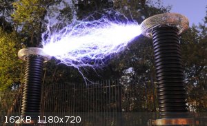
I forgot to mention what I am actually trying to achieve, which may affect your suggestions. I am trying to verify or dismiss some of the effects
usually associated with Tesla's various devices, such as transmission through Faraday cages, or wireless power transmission. I know many of these
ideas haven't actually been demonstrated (recently, at least) , but I think they are worth experimentation. These kinds of effects (according to
Tesla) are disrupted by the breakdown of the surrounding atmosphere, which form the sparks many TC builders desire. My goal is not to create sparks,
but to maximize the energy which is stored in the device. Another idea I have is the cooling of the device to super-low temperatures using liquid
nitrogen, which might increase the power to a large extent. Tesla reportedly did this too.
This is the main reason I want to stay as close to the original designs as possible.
Back to the actual discussion--
So in a normal SGTC the primary tuned circuit doesn't have to exist constantly for it to work, and the primary capacitor can function as both a part
of the switching mechanism and the primary tuned circuit? After the primary tuned circuit "rings down" , and the spark gap is extinguished, does the
secondary tuned circuit store the remaining energy? Or is the resonant energy of the secondary tuned circuit dependent on the primary tuned circuit
being present? What I'm trying to ask is if the secondary LC can store energy without the existence of the primary LC.
But this might be where my plans differ from many other TC plans. Since most TCs are designed solely for the creation of large sparks, the peak
voltage would probably be the main (or sole?) goal of those designs. This might not require the device to have energy in the LCs continuously, since
it would be the peak voltage that matters, not the ability to build up energy. Is this what you mean by "impulse coils", because they only operate
during each "push" of energy (the spark gap breaking down)?
If this is the goal of most SGTC designs, then it makes more sense to me. Or maybe the above paragraph is pure speculative nonsense . Assuming it is true, I want to try to preserve the energy from each successive
"push" of energy, which might require a continuously active primary LC? Wouldn't that require the power supply to work at the resonant frequency? Of
course, as we stated before, this would require large inductances and capacitances, as well as (in the case of SGTCs) high speed rotary spark gaps. I
won't worry about those design challenges right now.
I will keep trying to dig up the original plans and theories, and will probably update this thread soon. Thanks for helping
|
|
|
Sulaiman
International Hazard
Posts: 3558
Registered: 8-2-2015
Location: 3rd rock from the sun
Member Is Offline
|
|
look at the Wikipedia Tesla Coil page https://en.wikipedia.org/wiki/Tesla_coil
I think that you want a continuous wave Tesla coil.
in a typical 'sparks'n'arcs' TC most of the input power goes to the arcs, then spark gap and I2R losses.
A secondary on its own looses energy mainly to I2R and corona losses, with some near field absorbtion, and negligible electromagnetic
(Hertzian in the far field) losses.
If you consider a typical 300 kHz TC, e.m. wavelength = 1000 m
so 'wireless power' within a few hundred meters is near field,
energy transfer is generally by magnetic and/or capacitive coupling, non-Hertzian.
I have not come across proof that N.Tesla ever efficiently coupled his TCs to the ionosphere for his world power distribution scheme.
P.S. for high voltage without sparks you could consider a magnifying transmitter https://en.wikipedia.org/wiki/Magnifying_transmitter
basically a TC primary and an extra coil as a step-up transformer, base-feeding the 'secondary', (with various interactions)
electronic inverter base-drive of just a high 'Q' secondary would be another way to c.w. ehv
or magnetically drive the secondary as in the very popular Continuous Wave Solid State Tesla Coil (google cw-sstc)
There are so many websites with lifetimes of TC information.
[Edited on 14-9-2016 by Sulaiman]
[Edited on 14-9-2016 by Sulaiman]
[Edited on 14-9-2016 by Sulaiman]
CAUTION : Hobby Chemist, not Professional or even Amateur
|
|
|
wg48
National Hazard
Posts: 821
Registered: 21-11-2015
Member Is Offline
Mood: No Mood
|
|
Below is a link to a video of an mechanical analog of the coupled primary and secondary of a classic impulse Tesla coil. Its a demonstration of two
coupled pendulums. The initial lift of one of the pendulums corresponds to the charged primary capacitor when the spark gap conducts.
A mechanical analog of a magnifier type Tesla coil would have three coupled pendulums not necessarily with the same type of coupling between them.
A driven CW inductively coupled tesla coil would have one pendulum with the man rhythmically tugging on the spring.
https://www.youtube.com/watch?v=CguKKl9mX2s
Here is nice Java simulation of coupled pendulums you can play with. The graphs are equivalent to the voltages on the primary and secondary.
http://www.walter-fendt.de/ph6en/coupledpendula_en.htm
And even better, a page from Richie Burnett's Tesla Coil site. Its got the pendulum analogy too. An excellent site. Its British of cause LOL
http://www.richieburnett.co.uk/operation.html
[Edited on 14-9-2016 by wg48]
[Edited on 14-9-2016 by wg48]
|
|
|
| Pages:
1
2 |


