nlegaux
Hazard to Self

Posts: 93
Registered: 28-11-2014
Location: East Tennessee
Member Is Offline
Mood: No Mood
|
|
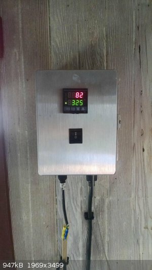
PID Temperature Controller
A PID temperature controller such as the one shown here can be used to accurately control the temperature of hotplates, lab furnaces, and other similar pieces of equipment. Additionally, it can be
used for more accurate melting point analyses. The design presented here does not require the modification of existing heating/cooling equipment and
can be used on multiple pieces of equipment (just not at the same time).
The materials used are as follows:
- A MyPin model TD4 PID
- A MyPin SSR-25 DA relay
- A heatsink
- A type K thermocouple
- A heavy duty outdoor extension cord
- Assorted fasteners/hardware (wire, nuts, etc...)
- An 8"x6"x3" project box
The first four items can be purchased online on Amazon, and the project box can be purchased at Radioshack. All other materials can be bought at
nearly any large retailer.
To begin, a square is cut into the project box to allow the PID to be mounted. Following this, two holes the same diameter as the extension cord are
drilled into the front and back of the box. A smaller hole is also drilled into the front of the box for the thermocouple. The extension cord is cut
in half in order to expose the wires inside (you will need both the male and female ends).
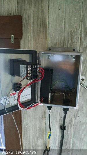
The next steps involve wiring the controller. The exact way in which this is done will vary depending on what model and brand of PID you have, so be
sure to check the Owner's manual of your device. Each row in the diagram below indicates a connection. For example, row 2 of the chart indicates that
terminal 1 on the PID needs to be wired to terminal 1 of the relay and row 3 of the chart indicates that terminal 2 of the PID needs to be wired to
the hot (black) wire of both the female and male sides of the cord. Zip ties were attached to the cables to prevent damage due to them being pulled.
Table
Wiring
Before closing the box the device was tested using an electrical kiln and was found to work correctly.
Finished Product
To use the controller, plug it into the wall and the equipment it will be controlling into it. Next, insert the thermocouple into the equipment and
set the temperature on the PID display. When changing from one piece of equipment to the other the PID must be recalibrated. Directions on how to do
this should be included with the manual for the PID.
nlegaux
[Edited on 10-10-2015 by nlegaux]
|
|
|
Magpie
lab constructor
Posts: 5939
Registered: 1-11-2003
Location: USA
Member Is Offline
Mood: Chemistry: the subtle science.
|
|
I have built two of these and show one somewhere on this forum. I find them very useful for controlling my muffle furnace, tube furnace, and oil
bath. As watsonfawkes said "automatic control beats the hell out of manual control" or something to that effect.
The single most important condition for a successful synthesis is good mixing - Nicodem
|
|
|
Sulaiman
International Hazard
Posts: 3558
Registered: 8-2-2015
Location: 3rd rock from the sun
Member Is Offline
|
|
Nice project, may I add a couple of suggestions?
Ventilate the box,
if not the insides will be hot enough to severely shorten component lives
Heatsink the module,
to allow more than a couple of amps before overheating
Reminder to replicators ... be sure to choose the SSR type as above,
not the relay output type that wears out and worse - makes sparks.
P.S. for UK eBay users, I have one of these in the mail
I'll try to give a quick review when it arrives.
http://www.ebay.co.uk/itm/311389111031?_trksid=p2060353.m274...
£9.58 for controller, SSR and thermocouple probe.
P.P.S.
unlike relay output controllers which physically break a connection
an SSR uses a triac (or sometimes two thyristors) as a switch,
low leakage but enough to give false readings of no-load output
and enough to give quite a 'tingle' when OFF.
[Edited on 11-10-2015 by Sulaiman]
|
|
|
nlegaux
Hazard to Self
Posts: 93
Registered: 28-11-2014
Location: East Tennessee
Member Is Offline
Mood: No Mood
|
|
Good suggestions Sulaiman; I will cut some holes in the box to allow for better ventilation and add a heatsink to the module (overheating is
definitely something to avoid!).
nlegaux
|
|
|
Sulaiman
International Hazard
Posts: 3558
Registered: 8-2-2015
Location: 3rd rock from the sun
Member Is Offline
|
|
My £9.58 temperature control kit arrived today, controller, 40A SSR, type K thermoucouple probe.
So as promised, a quick review. For a quick test I used a 240 V 100W filament lamp as a load
and suspended the thermocouple above it so that hot air from the lamp heated the thermocouple.
Works well, I could see the PID loop tuning itself.
The PV settled to within +0C and -0C of SV with an occasional -1C
Quality is good but not (for example) Omron quality but looks and feels better than expected.
Now to get back to the operator manual ... in Chinese.
Next week I will check the thermocouple input calibration.
This model has no alarm output which would allow unattended operation.
|
|
|
crazyboy
Hazard to Others
Posts: 436
Registered: 31-1-2008
Member Is Offline
Mood: Marginally insane
|
|
Here's my unit, wall mountable.
|
|
|


