| Pages:
1
2 |
aga
Forum Drunkard

Posts: 7030
Registered: 25-3-2014
Member Is Offline
|
|
Use 7 and recalculate for the reduced capacitance.
Voltage tolerance of the stack just increased by 1200V.
|
|
|
wish i had a kraken!!!
Hazard to Others
Posts: 157
Registered: 22-3-2012
Member Is Offline
Mood: No Mood
|
|
Quote: Originally posted by IrC  | | kracken it appears to me you have never been or been around someone seriously injured toying with these levels of energy. I could be wrong but wanting
near 4KV at 2 amperes for a vague wide variety of dangerous projects including charging a 'high farad' 8KV capacitor bank for whatever project leads
me to believe I am correct. |
Tanx Dear IrC, I don't wanna toy with it, I just want to have such a power supply and I am here asking U (GODS of electronics) cuz I want to discuss
my plans for it with U guys before taking any step/s.
| Quote: Originally posted by IrC |
I spent some time looking through pages in the site you linked and the author is very skilled in electronics. However going through his magnetron
pages and watching the vids leads me to think he has the common sense of a lemming so be very careful in what you choose to replicate. For example
capacitors in the bank you described charged as you are saying can vaporize themselves with tremendously destructive violence. All I can say is be
very careful. If you seriously need such energy levels I would get a 14.4 KV 10KVA pole pig and use a variable core arc welder as an adjustable series
reactor instead of trying to combine ever increasing numbers of MOT's. Just a thought.
|
Your idea is good but U know, I do Have 12 MOTs (900 Watts) and 6 of those Capacitors, and I don't have access to pole pig and a variable core arc
welder ! that's why I intend to use them.
|
|
|
wish i had a kraken!!!
Hazard to Others
Posts: 157
Registered: 22-3-2012
Member Is Offline
Mood: No Mood
|
|
| Quote: Originally posted by aga | Use 7 and recalculate for the reduced capacitance.
Voltage tolerance of the stack just increased by 1200V. |
Ok , Tanx
But could U explain more why 7 ?
I think 6 * 1200V = 7200 V , which is at least 900 Volts higher than the out put voltage of power supply . Could U explain me in more details why 7
is better to be used ? I mean would U tell me why U think 6 is not sufficient ?
[Edited on 21-10-2015 by wish i had a kraken!!!]
|
|
|
MrHomeScientist
International Hazard
Posts: 1806
Registered: 24-10-2010
Location: Flerovium
Member Is Offline
Mood: No Mood
|
|
Shouldn't you have the poles of those capacitors connected when not in use, so they don't accumulate charge from static electricity?
|
|
|
IrC
International Hazard
Posts: 2710
Registered: 7-3-2005
Location: Eureka
Member Is Offline
Mood: Discovering
|
|
I figured you were going MOT because as you say pole pigs are next to impossible to source unless your pockets are deep. Post a proposed schematic. I
assume you intend to rectify the voltage and are using those caps in series to store a high DC voltage? I do not see any diodes in your pics.
Obviously peak voltage is what you need to consider as to the total rating of the string. Your information is confusing and sparse I need to see the
actual circuit you intend to build.
"Science is the belief in the ignorance of the experts" Richard Feynman
|
|
|
WGTR
National Hazard
Posts: 971
Registered: 29-9-2013
Location: Online
Member Is Offline
Mood: Outline
|
|
I have a headache today, so I hope this post comes out sounding coherent. The problem that myself (and maybe IrC) have is that we know what kinds of
things can go wrong when dealing with high voltage and high energy. It's difficult to cover every possible safety issue with someone who admits not
knowing much about electronics just yet. We may overlook something important, or something we say might be misunderstood, and we might end up
instructing you to do something that would end up killing or injuring you. Even if we wouldn't be legally liable, it falls under a moral
responsibility to not suggest things that could be injurious to someone who's inexperienced in the field. That's why you're getting more safety
advise than actual answers to your questions.
Anyway, it's not such a simple matter to connect capacitors in series. You first have to measure the capacitance of each cell, to make sure that they
are matched (especially for the type that you have). If they aren't, then they will divide the voltage unevenly, and some capacitors may exceed their
voltage rating, which can cause the entire string to fail. If they are within their tolerances, then doing as aga suggests would probably work. You
add additional cells in series to give you some more voltage headroom, just in case one or more of them is out of tolerance. Then if one of them
shorts out, the rest of the capacitors usually don't automatically fail. These oil-filled capacitors often change capacitance and fail, however.
Also, the capacitors must be mounted in a specific orientation. I don't remember which one off the top of my head, but it may tell you on the side of
the can. They are oil-cooled internally, but the manufacturer only puts enough oil in to cover the foil, if it is mounted a certain way. Otherwise
parts of the foil are not submerged, and those areas can overheat/melt during use.
This isn't as important for AC use, but for DC use it is important to consider the leakage current of each capacitor. It is generally low, but over
time it can cause the voltages across series capacitor strings to become unbalanced. One way to counteract this is to add external resistors across
each capacitor, such that the resistor current is at least 10 times greater than the worst leakage of any capacitor in the string.
|
|
|
IrC
International Hazard
Posts: 2710
Registered: 7-3-2005
Location: Eureka
Member Is Offline
Mood: Discovering
|
|
All that, and it keeps nagging at me from all the posts I have seen I can't quite figure out if he intends to put that cap string across an AC high
voltage. Hope not.
"Science is the belief in the ignorance of the experts" Richard Feynman
|
|
|
wish i had a kraken!!!
Hazard to Others
Posts: 157
Registered: 22-3-2012
Member Is Offline
Mood: No Mood
|
|
| Quote: Originally posted by IrC | . Post a proposed schematic.Your information is confusing and sparse I need to see the actual circuit you intend to build.
|
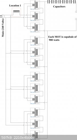
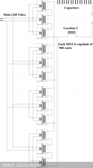
Dear IrC , here is my proposed schematic , I want to build a multi functional
HV Powersupply . there u would see two slightly different schematics , are they the same ? which one would have better operation at the same cost ?
Plz guide me (I don't want to have my MOTs getting hot when I use them for at least 30 minutes so I need to know how to calculate magnitude of current
limiter and to put it where to achive what I want )
I am supper sorry for my late reply, I was supper busy with something.
I will let U know about them soon :-)
| Quote: Originally posted by IrC |
I assume you intend to rectify the voltage and are using those caps in series to store a high DC voltage? I do not see any diodes in your pics.
Obviously peak voltage is what you need to consider as to the total rating of the string.
|
U are 100% right , there is no diodes , I have separated rectifying unit from the Power supply, The intention for using capacitors is to provide more
amps So, some huge arcs would be appear when I use the power supply for my Jacob ladder (as I said already , I intend to have multi functional PS ).
[Edited on 12-11-2015 by wish i had a kraken!!!]
[Edited on 12-11-2015 by wish i had a kraken!!!]
 
|
|
|
wish i had a kraken!!!
Hazard to Others
Posts: 157
Registered: 22-3-2012
Member Is Offline
Mood: No Mood
|
|
| Quote: Originally posted by IrC | All that, and it keeps nagging at me from all the posts I have seen I can't quite figure out if he intends to put that cap string across an AC high
voltage. Hope not.
|
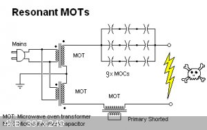
What is wrong with adding cap string across an AC high voltage ?
(PLZ visit : http://uzzors2k.4hv.org/index.php?page=resonantmots , I used this circuit to make my PS)
But mine is slightly different :
|
|
|
wish i had a kraken!!!
Hazard to Others
Posts: 157
Registered: 22-3-2012
Member Is Offline
Mood: No Mood
|
|
| Quote: Originally posted by WGTR |
Anyway, it's not such a simple matter to connect capacitors in series. You first have to measure the capacitance of each cell, to make sure that they
are matched (especially for the type that you have). If they aren't, then they will divide the voltage unevenly, and some capacitors may exceed their
voltage rating, which can cause the entire string to fail. If they are within their tolerances, then doing as aga suggests would probably work. You
add additional cells in series to give you some more voltage headroom, just in case one or more of them is out of tolerance. Then if one of them
shorts out, the rest of the capacitors usually don't automatically fail. These oil-filled capacitors often change capacitance and fail, however.
Also, the capacitors must be mounted in a specific orientation. I don't remember which one off the top of my head, but it may tell you on the side of
the can. They are oil-cooled internally, but the manufacturer only puts enough oil in to cover the foil, if it is mounted a certain way. Otherwise
parts of the foil are not submerged, and those areas can overheat/melt during use.
This isn't as important for AC use, but for DC use it is important to consider the leakage current of each capacitor. It is generally low, but over
time it can cause the voltages across series capacitor strings to become unbalanced. One way to counteract this is to add external resistors across
each capacitor, such that the resistor current is at least 10 times greater than the worst leakage of any capacitor in the string.
|
Thanks Dear WTGR, I measured the capacitance (~12.5 MicroFarad each slightly different , Like 12.3 or 12.6 Is it going to make trouble ?)
And I want to connect 8 of them in series for AC use.
|
|
|
IrC
International Hazard
Posts: 2710
Registered: 7-3-2005
Location: Eureka
Member Is Offline
Mood: Discovering
|
|
I cannot see the image in the post above the one quoted here. In this circuit (in quoted post) the caps are not across the high voltage they are in
series with it. To say 'across' is to say in parallel. When you are using capacitors of the proper value to resonate at the line frequency with the
transformer inductance you are in effect altering the power factor.
"Science is the belief in the ignorance of the experts" Richard Feynman
|
|
|
wish i had a kraken!!!
Hazard to Others
Posts: 157
Registered: 22-3-2012
Member Is Offline
Mood: No Mood
|
|
Dear IrC, did U click on the images U can't see ?
I believe if U do click on them your browser will open a new page in which U can see them.
|
|
|
Sulaiman
International Hazard
Posts: 3558
Registered: 8-2-2015
Location: 3rd rock from the sun
Member Is Offline
|
|
Ignoring the chokes in your first diagram,
the main difference in the second diagram is that the mot cores and secondaries have been drawn as 'floating'/isolated,
in the first diagram you can see the connection between the inner part of the secondary winding and the core.
(having the inner part of the winding at the same potential as the core makes electrical insulation easier/cheaper)
look at the first diagram and imagine
. what voltage is each core at
. what simple tricks can be used to reduce insulation problems
off to work ....
|
|
|
wish i had a kraken!!!
Hazard to Others
Posts: 157
Registered: 22-3-2012
Member Is Offline
Mood: No Mood
|
|
Dear Sulaiman , My intention is to use this PS unit for at least 30 minutes without having MOTs getting hot , So , the purpose of the chokes is to
act like a current limiter and prevent MOTs from getting over heated .
So U suggesting me to put the chokes in location number 2?
|
|
|
Sulaiman
International Hazard
Posts: 3558
Registered: 8-2-2015
Location: 3rd rock from the sun
Member Is Offline
|
|
No, I am referring to the physical construction of an MOT being represented in the first diagram but not in the second.
For cost and safety reasons, the core of an MOT is normally connected to chassis earth and the inner connection to the secondary winding is connected
to the core.
Have a look at your transformers.
|
|
|
IrC
International Hazard
Posts: 2710
Registered: 7-3-2005
Location: Eureka
Member Is Offline
Mood: Discovering
|
|
Obviously I know how to click on an image link. It is far too large and png displays as black traces on a near black background on my browser.
"Science is the belief in the ignorance of the experts" Richard Feynman
|
|
|
wish i had a kraken!!!
Hazard to Others
Posts: 157
Registered: 22-3-2012
Member Is Offline
Mood: No Mood
|
|
I am so sorry, I'll fix it soon
[Edited on 13-11-2015 by wish i had a kraken!!!]
|
|
|
IrC
International Hazard
Posts: 2710
Registered: 7-3-2005
Location: Eureka
Member Is Offline
Mood: Discovering
|
|
Your circuit is not 'slightly different' than the link. It is not even close, I do not see how your design will work. Also I do not believe the
insulation resistance between the secondary and core is adequate. Running at design voltage each secondary (the ones even wired so as to work) will
have a peak voltage of 2,800 volts. I do not see how any house wall outlet is going to provide around 11 KVA for one minute let alone 30 minutes. All
I see is a member working for at minimum a near death experience. I do not recall in this thread a diagram of just exactly what this supply will be
connected to.
"Science is the belief in the ignorance of the experts" Richard Feynman
|
|
|
wish i had a kraken!!!
Hazard to Others
Posts: 157
Registered: 22-3-2012
Member Is Offline
Mood: No Mood
|
|
Dear IrC , I meant my actual PS (the one that I already built) is using 9 HV capacitors , insted of 4 .(" http://uzzors2k.4hv.org/index.php?page=resonantmots "the guy used 4 capacitors in his work (total capacitance = 1 MicroFarad) , but i feared maybe
there would be some problems, so I added 5 more caps to have a total capacitance of 1 MicroFarad )
| Quote: Originally posted by IrC |
I do not see how your design will work. Also I do not believe the insulation resistance between the secondary and core is adequate.
|
In my diagram I connected 3 MOTs in series So, I hope the outlet voltage will be 6300 Volts , then I connected 4 of these in parallel so , I hope the
outlet Amp will be 4 times bigger.
I just don't know if it is as simple as I think , I hope U help me with that .
I don't know how to become sure that in my design MOTs would be in phase?
And why U think the insulation is not adequate cuz I have seen successful attempts of connecting 3 MOTs in series:
https://www.youtube.com/watch?v=fAyHEe8lzR0
http://www.youtube.com/watch?v=dmOrXH9X7LE
https://www.youtube.com/watch?v=bHSAZ7fDy7Y
| Quote: Originally posted by IrC |
Running at design voltage each secondary (the ones even wired so as to work) will have a peak voltage of 2,800 volts. I do not see how any house wall
outlet is going to provide around 11 KVA for one minute let alone 30 minutes. |
Dear IrC, PLZ explain this part more .
| Quote: Originally posted by IrC |
I do not recall in this thread a diagram of just exactly what this supply will be connected to.
|
As I told before It would be a multi functional PS . I want to use it in my investigation of the effect of higher voltages on sputtering process ,
also investigate the time and other parameters.
[Edited on 13-11-2015 by wish i had a kraken!!!]
|
|
|
IrC
International Hazard
Posts: 2710
Registered: 7-3-2005
Location: Eureka
Member Is Offline
Mood: Discovering
|
|
"Dear IrC, PLZ explain this part more ."
I am not trying to be difficult here but this question really bothers me. Helping someone build and experiment with such a potentially lethal circuit
when it is clear they lack basic understanding of the theory involved does not bode well. An analogy would be one of SCM's energetic gurus helping
someone make NCl3 where the reaction is being carried out in a paint shaker. Failure to understand concepts as simple as my 'nearly 11 KW' statement
is troublesome to me. 12 MOT's each capable of 900 watts (0.9 KW) yields a total of 12 x 0.9 = 10,800 watts or 10.8 KW. The rated value of each (900
watts) is that which can operate for several minutes nonstop cooking food without overheat melting the primary enameled turns causing a short circuit.
In reality during an arc with very high loading on the output far greater than 900 watts can be seen by each MOT so the 10,800 watts could actually be
greater. This is far in excess of any normal house wiring. You would have to run your own line to the service box with say a dual 50 amp breaker on
the 240 volt circuit. Also if you carefully study the schematic you provided your primaries are not wired the same as any of the vids you linked. In
each set of three you only power the center one. If one were to assume you meant dots instead of crossovers then the phasing would be a disaster. As
to not knowing the 2800 peak volts I mentioned, magnetrons are the same here or in the Eu so whether or not the MOT primary was designed for 120 or
240 volts the output would be the same or very similar. Study the circuit theory of a typical microwave oven in this link.
http://www.microtechfactoryservice.com/doubler.html
"The voltage across the capacitor will rise to the transformer secondary voltage to the maximum 2800 volts"
This 2800 volts is the peak voltage seen on the secondary winding at the proper moment in time during the cycle, three in series assuming phasing was
correct will yield a peak voltage of 8400 volts for the series string. All MOT's are designed and the insulation resistance is considered with the end
of the innermost winding being connected to the core, and the oven frame to the green ground wire in the power cord. Which is connected to the
building neutral. You will have a situation where the voltage will try to arc to the core, and the insulation of the primary side is not designed to
withstand this voltage between the core and the primary winding. Also for sputtering you want high voltage at moderate current for long times whereas
the high leakage MOT is designed for very high current for a relatively short time interval. While I am not saying the idea will not work (assuming
you corrected the schematic you provided concerning primary wiring with due consideration of phasing), it is a dangerous poorly thought out design
suitable for short duration cool looking arcs but not long term operation such as you would need for sputtering. I suggest you design two supplies,
one for sputtering and one for playing with short duration arcs.
"Science is the belief in the ignorance of the experts" Richard Feynman
|
|
|
Marvin
National Hazard
Posts: 995
Registered: 13-10-2002
Member Is Offline
Mood: No Mood
|
|
| Quote: Originally posted by IrC | | In each set of three you only power the center one. If one were to assume you meant dots instead of crossovers then the phasing would be a disaster.
|
I made the same mistake the first time I looked at the new one, and then I made the same assumption. Actually the phasing is fine, the schematic
contains 4 way ties.
I'm finding this one much less funny, I see a plain circuit that looks functional and the same total lack of understanding. This is two orders of
magnitude greater than anyone really needs for sputtering from what I've read. It's a mistake that could easily kill the first person that tries to
use it and the first person that tries to save them, which could be a family member or someone from emergency response.
|
|
|
wish i had a kraken!!!
Hazard to Others
Posts: 157
Registered: 22-3-2012
Member Is Offline
Mood: No Mood
|
|
Dear Marvin , U believe my circuit will work?
Can I draw Arc from this PS for long duration from it ? (30 minutes at least )
IrC made some points which are noticeable and I think I have to change the circuit in order to achive what I want , But I hope I don't have to leave
it.
I don't say I am going to use it only for sputtering , I want to use it in especial sputtering (I want to achieve higher temperatures and investigate
the effects of it with respect to time on deposited layer.) & I also want to use this PS on carbon nanotube/Fulleren production in underwater AC
electric arcing (Some have done this using 40 Volt at approximately 100 Amps but I want to use 6300 Volts and see the difference myself I mean do U
think it would be possible to achive longer arcs under water ? Or it wont work ? )
[Edited on 16-11-2015 by wish i had a kraken!!!]
[Edited on 16-11-2015 by wish i had a kraken!!!]
|
|
|
Texium
|
Thread Moved
22-11-2023 at 19:51 |
| Pages:
1
2 |


