| Pages:
1
2
3 |
SupaVillain
Hazard to Others

Posts: 171
Registered: 28-10-2014
Member Is Offline
Mood: No Mood
|
|
Sawed through 3" inches of aluminum rod to get the 1st stage piston, gonna grind it up tomorrow to fit in its cylinder, "pivot balls" and their "caps"
or "bearings" are the names of the devices attaching the piston rods to the swash plate/ball bearing, I've found a 5/8" shaft and ball bearings, but
am looking at bearings with shaft flange now, and I've got a 5" sheave, along with a 12" sheave, made of Zamak 3, to be reliable in transmitting 5
horsepower to the compressor with an A belt. Found a 6" ball bearing for cheap, worried that it might not handle the amount of thrust though. Found
out that the bottom area of the swash plate is just a thrust bearing or two... like ball bearings, but are limited in left and right movement by
blocks, held together by bolt with spring, and these bearings are running against "thrust riders"...basically this keeps the alignment of the whole
plate, by forcing this bottom area into a back and forth motion that the pistons require. Will likely be tie-ing down my angle grinder to a block of
wood so that I can utilize the 1/16" width of cutoff wheels on the o-ring cavities.... or at least on the really wide ones. Made another zvs driver
but for voltage, and for my SEM, might be able to use it for this laser project as well. It is nice because after learning about negative voltages,
its isolation flyback transformer can meet a ground, and everything between that and the negative end of the secondary coil will be negative. I'm
assuming that since the anode is grounded and its the cathode that the discharge starts on, that I'll be using negative voltages. Soldering a 92 piece
string resistor voltage divider took a while.... however that is only for 12kV, but could easily add more in series for the laser voltages of 16-20kV.
I don't know if by "pulse" they(these patents) mean frequency, or capacitor discharging pulses, or something entirely unknown to me.
[Edited on 28-7-2016 by SupaVillain]
Oh.
|
|
|
SupaVillain
Hazard to Others
Posts: 171
Registered: 28-10-2014
Member Is Offline
Mood: No Mood
|
|
After trying many ways, finally found the best way I can carve out the o-ring grooves..... First piston takes longest time to make and is allowed to
have more defects than others as it is working with the least amount of pressure. Any fix could be done with jb weld, it is strong enough for the
pressures and wear but only in this stage. The viton isn't falling out of the grooves. Also, noticed the spiral o-ring patent doesn't mention viton,
and they actually used much harder materials, so the viton could be vulcanized together, and like stated before, this is stronger than the viton
alone. It's worth making something much harder to install and remove than it is to have something like the spirals that might not work. Might put a
thin layer of glue between my non-precise machining of only the rider rings, so that a flat seal is made, but it's not necessary as they don't help
with the compression. I now have almost every part but the main block, thrust rods, the "cant" of the shaft, etc. Trying to find a way to fasten 5/8"
bolts to the ball bearing....
Oh.
|
|
|
SupaVillain
Hazard to Others
Posts: 171
Registered: 28-10-2014
Member Is Offline
Mood: No Mood
|
|
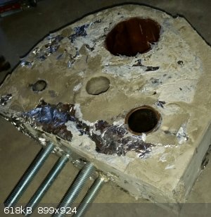
decided to pour a cement cylinder block, because easy, cheap, and I'm confident that it will work. Yes it crumbles every time you move it, but this is
only the far outside. It is much, much thicker around the cylinders than the regular metal version. Don't remember if I said this or not, but I have
already visualized the interior design of the reed valves, and I guess that will be the next part I work on. Did a ton of work on electronics, now
have two microwave oven transformers(secondaries modified), to supply and limit current to the mazilli zvs circuit for the laser. Pulled some nice
little purple sparks with a ccfl inverter and touched the actual circuit after safely discharging, so high voltage safety is now under my belt as
well.
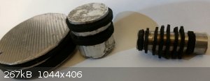
and here's the pistons, 3rd needs some trimming on the viton, and 1st will have to be installed backwards to work because its first ring is too skinny
and not deep enough to stay put. Will redo the first piston.
[Edited on 22-8-2016 by SupaVillain]
Oh.
|
|
|
SupaVillain
Hazard to Others
Posts: 171
Registered: 28-10-2014
Member Is Offline
Mood: No Mood
|
|
So pistons are really hard to make when they're bigger because the chance of them being oval shaped and not applying the o-ring perfectly gets harder,
especially since viton doesn't compress very much.
I FOUND NEON FOR $20 FOR 0.9 LITERS AT WENSCO.COM because I did another search and this time used duckduckgo instead of google.
Re-calculated and I think one of these things will give me twice the amount I need. (https://www.wensco.com/CatSearch/549/neon-red-gas)
Platinum Resistance Thermometers.... There are cheap ones on ebay sometimes, which I would rather now just forward that cost to the neon.
I also got a cheap old rectifier for like 800amps and two microwave oven transformers(one as an inductor to limit current) to weld the 5/8" threaded
rods onto the ball bearing....
I will finish this compressor with time, since I still have lots of uses for it and almost every part but I'm in school and the laser is what I'm
really rushing here. Will be looking at laser power supplies so I can see if I need any other effect other than just high voltage.
Oh.
|
|
|
SupaVillain
Hazard to Others
Posts: 171
Registered: 28-10-2014
Member Is Offline
Mood: No Mood
|
|
Okay so I may use a submersible DC brushless motor since youtube shows they work underwater, the liquid being krytox of course
attached pic is the pulsed laser power supply without actual Mazilli power supplies. I have my MOT's set up as well to supply the Mazillis, will
probably need a battery for the second one....
The pipes are the PVC pipe as salt water leyden jar capacitors, tested and fine but I might need one more layer...Transformers in the bag will have
mineral oil on them, I could only find baby oil.
the schematic for the laser power supply is Fig. 30 here
Trying to finalize the idea of using this closed chamber pressurizing technique in this video using Boyle's law, may need to combine it with Gay-Lussac's law using
dry ice as well though... the problem is trying to start with the 0.9 liters of neon volume i'd get with the wensco bottle, and then trying to
compress it to only around 0.5, not enough of a jump unless I could fill a greater valved off extension with a liquid....? confusing... anyways when I
get that done I can order the chems and put it together and turn it on.
[Edited on 9-10-2016 by SupaVillain]

Oh.
|
|
|
| Pages:
1
2
3 |
|


