| Pages:
1
2
3 |
SupaVillain
Hazard to Others
  
Posts: 171
Registered: 28-10-2014
Member Is Offline
Mood: No Mood
|
|
The problem with that is that those things and neon lights are under vacuum, this laser has to be at 3 atmospheres.
Oh.
|
|
|
SupaVillain
Hazard to Others
  
Posts: 171
Registered: 28-10-2014
Member Is Offline
Mood: No Mood
|
|
Called advanced specialty gases in NV, quoted 25L lecture bottle for $325, nGlantz was, if you're a business, $369 for that amount, or $178 for 10L,
but if you're not a business then it costs over a thousand. Don't remember which one was then costing that much but wow. Still waiting on quote from
Praxair and called them today for quote, still waiting on call back. However, I have found that I can build a scuba compressor(I have schematics and
manuals) and liquefy air by myself, like this guy here (http://homemadeliquidnitrogen.com/) There are 5-7 horsepower gas motors on craigslist from mowers and such, for less than $60 in my area. Just saw
one for $35, and the actual compressor, well... I had already looked into this because I need to paint my car. Been driving around a cosmetically
wrecked car for 2 years now because I care more about funding science projects than what others think of my car. It would cost less to build this
compressor and make my own neon than it would to buy neon, especially because I already need it for other reasons, including supplying gas to my SCBA
PPE. This might take some time to do... Neon being at 18.2 ppm in the atmosphere is the most annoying part. Running a 6cfm compressor for an hour
would give me.. I think 0.18 liters of neon. Thankfully its boiling point is quite far from other gases, with the exception of helium.
[Edited on 1-7-2016 by SupaVillain]
Oh.
|
|
|
careysub
International Hazard
    
Posts: 1339
Registered: 4-8-2014
Location: Coastal Sage Scrub Biome
Member Is Offline
Mood: Lowest quantum state
|
|
Between DoctorOfPhilosophy and Supavillain I am greatly impressed!
A working CO2 laser, plans for a fluorine laser AND for harvesting neon from the wild!
|
|
|
SupaVillain
Hazard to Others
  
Posts: 171
Registered: 28-10-2014
Member Is Offline
Mood: No Mood
|
|
Progress: I have read through the papers I have on a select compressor, and found the exact materials and dimensions of the pistons. The pressures
they need to be at, the air flow diagram, stroke, and more of its functionality were included. Also found multiple pictures online I am currently
making progress on the idea of making a device that would attach to my car to run the compressor. Otherwise I can go pick up an engine for it, well
within feasibility for my other uses. After researching DIY high voltage capacitors for other projects, and for the fact that I'm sitting next to a
mazilli ZVS driver, I may be able to make the capacitors instead of ordering a bunch, and use it for melting and casting the stainless steel piston
and cylinder, the piston is only 0.52 inches in diameter. This would probably be much easier than trying to use charcoal for that material. Someone
reported that these parts were actually just steel, but stainless is probably on the safer side. The other 2 pistons are apparently aluminum but look
bronze and the other cylinders are bronze. I found that some lead free solders are 95% tin, and I've got some copper pipe to melt. I have a ton of
aluminum and will use that for the block as well. Found out how to make greensand and where to buy the bentonite and sand for the cast forms. The
O-rings are Viton and spiral cut, and turns out their lube/grease is actually krytox. Today, I realized I don't need a compressible cylinder to keep
the neon because it would be so small and that I can apply Gay-Lussac's thermal/pressure law at that point because of the availability of liquid air.
Looked at some patents and found that the fan and motor are crucial, so I will probably have a super thin, (limiting volume) flattened tube that
stretches away from the laser, far enough to separate the magnets for it and the high voltage, although the whole copper body will be grounded. Seems
that a fully internal rotor, and external stator(permanent magnet) is best way to run the fan. Also considering just running thin tube from back and
front of laser cylinder and having the fan push the air in a loop, freshest air at front. Can't be stressed enough, the importance of the fan.
Inter-electrode distance can be from 8mm to 16mm(13mm is nominal according to patents) and electrode width should be about 1mm to 2mm. Kind of
possible to put it in a 1/2inch pipe but... keeping the high voltage cathode striking the anode instead of the outer body is another design
requirement. Honestly I think bringing the electrodes to sharp points in their middles is better than just rounding them. After looking at spark-gap
measuring of high voltages, there is a graph on youtube(https://www.youtube.com/watch?v=dO4yyYCVsSE) that shows the difference between spheres and sharp pointed wires. It is must easier for voltages to
cross through air or other gases with sharp pointed wires. The rounded nature of the outer body pipe, and pointed, or "mohawked" electrodes if you
will, might be enough to keep the gas discharging constantly and not skip to the ground. Anode is also held at ground but this discharge area is
designated for creating the constant light.
[Edited on 8-7-2016 by SupaVillain]
[Edited on 8-7-2016 by SupaVillain]
Oh.
|
|
|
DoctorOfPhilosophy
Hazard to Others
  
Posts: 130
Registered: 12-6-2012
Location: Ontario, Canada
Member Is Offline
Mood: enthralled
|
|
SupaVillain, it's as if we're long lost siblings. I also tried to build that machine and I can tell you it's not easy. Probably doable, but it's
absolutely, positively going to cost more than buying the gas. Even if you work an extra 40 hours (assuming minimum wage), it's well worth it.
I'm really surprised though that you can't find it from a neon sign maker. I could ask some people here, I've already done business with one guy and
his son is extremely fascinated by lasers so it could be an interesting request for him. I would need to have a way to ship the gas safely though. You
don't happen to live near Toronto?
PS I'm trying to parse your second message but its hard to think when I'm juggling two conversations on a dating site haha 
[Edited on 8-7-2016 by DoctorOfPhilosophy]
|
|
|
SupaVillain
Hazard to Others
  
Posts: 171
Registered: 28-10-2014
Member Is Offline
Mood: No Mood
|
|
Are you talking about the Rix SA-6? It's a very simple compressor, all I need to do is get the small pieces casted and grind and polish em. Well I
guess the bearing and rotor are going to be a little complex, but if I get this induction welder finished it will be easy. Doing quality work of a
"canted" rotor shaft without an induction welder would be extremely difficult, if possible. I've setup forge projects like this before. Eh, I honestly
need the compressor for other purposes, along with preparing an engine applicable to this and a lathe. I live in Kentucky, might be because police
state? I bet praxair would sell it to me but they never message or call back. Not currently working because I am in between college semesters, am on
"on-call" for jury duty, and working on getting computer/security certifications before school is back in session. Most places just don't care to sell
neon, only supply businesses, or their receptionists answered the phone instead of their tech people. There was another place I was going to email but
gave up and became excited about my current plan. I also consider it more of fun than work. I'm going pretty far out with these DIY ventures.
Yesterday I cut my own hair!
Tool attachment onto car:
https://www.youtube.com/watch?v=N1HZztie5ac
I also figured out why the pistons in my pics are so yellow like bronze, yet aluminum. They are chromated!
[Edited on 8-7-2016 by SupaVillain]
Oh.
|
|
|
DoctorOfPhilosophy
Hazard to Others
  
Posts: 130
Registered: 12-6-2012
Location: Ontario, Canada
Member Is Offline
Mood: enthralled
|
|
How about this, you focus on building all other components of the laser, and then I donate the neon gas once everything else is finished and
documented?
|
|
|
SupaVillain
Hazard to Others
  
Posts: 171
Registered: 28-10-2014
Member Is Offline
Mood: No Mood
|
|
That's very kind of you, but I really don't need financial support here, I am just very cheap because it means more projects for the same cost, and
there is a lot of pride in making your own equipment. Honestly if it doesn't work, I'll be calling up places for a Neon cylinder in that same minute I
find that conclusion. Even with a newly made business if I have to. I'm already making the fiberglass molds and hopefully finishing them tonight.
Thank you again for the support, it is really appreciated.
Oh.
|
|
|
DoctorOfPhilosophy
Hazard to Others
  
Posts: 130
Registered: 12-6-2012
Location: Ontario, Canada
Member Is Offline
Mood: enthralled
|
|
Ah ok that makes sense, in that case are you going to use that guy's air liquifier design or make your own? In any case I can help you do that
calculations properly. I found that mild steel pipe conducts too much thermal energy along the length of the heat exchanger (assuming thinnest
available wall thickness). Stainless steel has almost the optimal thermal conductivity for a practical (from an engineering standpoint) design. I
ended up spending $200 on SS pipe for the project.
On that guy's website, he's also using SS tubing but he doesn't show any engineering calculations. I wonder if he just got lucky by choosing the right
material...
|
|
|
SupaVillain
Hazard to Others
  
Posts: 171
Registered: 28-10-2014
Member Is Offline
Mood: No Mood
|
|
Well not really trying to copy that guy, his whole thing is about an adsorbent molecular sieve that removes oxygen I think, and I'm going for
distillation I think....
Actually fixed my calculations on the pipe volume, if I take my half inch copper pipe at 2 feet length, I can fill it in 1.5 hours, yet that's not
including the fan and its piping. I have finally decided how I'm going to seal the laser, yet still debating on dielectrics to separate the incoming
wires from the grounded tube. I don't trust my initial idea of having copper bolts silver-soldered to the cathode so that a tight nut could fasten a
seal, my final decision is to use slightly over 3mm of viton between cathode and top of tubing, and have copper wire wrapped in dielectric instead of
bolts. JB weld will take the task of making an air tight seal around these components, mostly just around the wire to the viton, and on the exterior
of the copper tube to the visible top of the viton. A generous amount of krytox will cover the interior of the viton so that the fluorine doesn't
affect it. I have confidence in that design, and part of actually getting this done is accepting the fact that nothing designed for fluorine
work will last forever.
For the compressor, it is basically just the same, or one model higher, than what he is using, and the needle valve to cause the joule-thomson effect.
The model is the Rix SA-6 and I have found manuals/schematics and such. Believe it or not but there is only about 8 feet or so IIRC of stainless
tubing, at 1/4 inches I believe. The other two coils are copper. I have taken the provided piston diameters and pictures of them to calculate their
lengths and other dimensions with ratios. The first two are aluminum, with bronze cylinders, the last stage is stainless for the cylinder and piston.
Picked up sand and bentonite for casting today. Found out my soldering iron is better than a hot wire cutter for cutting and "sanding" foam molds.
Oh.
|
|
|
SupaVillain
Hazard to Others
  
Posts: 171
Registered: 28-10-2014
Member Is Offline
Mood: No Mood
|
|
Pics and gathered info on the compressor
there's drawings in the manual and a reed valve service guide, but I won't upload in case it's too much data.
Piston Diameters
1st - 3 inches
2nd - 1.25 inches
3rd - 0.56 inches
spiral viton for all piston rings
videos:
https://www.youtube.com/watch?v=ELoWWdXpwXU
https://www.youtube.com/watch?v=6BgcEEiCukk
forums:
http://vintagedoublehose.com/forum/viewtopic.php?f=40&t=...
http://www.rebreatherworld.com/showthread.php?19952-Rix-SA-6-Instructions.(not so useful)
http://www.scubaboard.com/community/threads/rix-sa-6-parts-n...
patents:
http://www.google.com/patents/US6990889
http://www.google.com/patents/US4576381
http://patents.justia.com/assignee/rix-industries
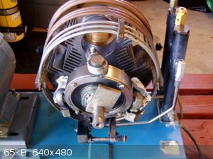 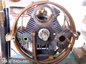 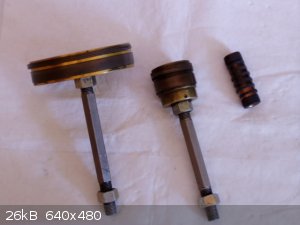
Oh.
|
|
|
SupaVillain
Hazard to Others
  
Posts: 171
Registered: 28-10-2014
Member Is Offline
Mood: No Mood
|
|
Just picked up the 8 HP engine to run the compressor. (Equal to 5 HP electric) Not gonna waste time trying to make something that might damage my
car... Eventually felt a disc pulley connected to the bolts would be best as it wouldn't ram into the car if the wheels turned. Then realized that I
have no idea if it could hold a belt with tension, without turning. Realized I could use it as a lathe to make the cylinders and pistons precisely,
more easily. This should also be much faster than improvising with my car.
For the fan, I'll have no leaky dirty feedthrough business with fluorine. I found out the usual plating on neodymium magnets is nickel, and i'll have
them held on a copper bar, as opposed to a teflon coated magnet stir bar, and fins upon this. I have motors from a printer to do this. Spent many
hours frustrated with magnets, attempting different designs. YouTube is swamped with "free energy" crap to the point where there's no guarantee what
is legit and what isn't. ****ing magnets, how do they work? One of the biggest issues with magnets is that heating them weakens them, and can even
remove their magnetic field. This might require some viton valve to allow the copper stir bar in after soldering of the copper body.
I think for a ball bearing/swash plate, I'm just going to get a ball bearing for the make and model of my car, as I'd assume it can handle the
compressor if it can handle a car. I think the actual one in the pics above are about 6.25 inches... they get real expensive well before they reach
that size. Of course I would have to weld the bearing to more metal that I would bolt the piston's thrust rods to.
[Edited on 13-7-2016 by SupaVillain]
Oh.
|
|
|
Tsjerk
International Hazard
    
Posts: 3022
Registered: 20-4-2005
Location: Netherlands
Member Is Offline
Mood: Mood
|
|
I'm sorry for questioning you, good luck getting this thing to work!
|
|
|
SupaVillain
Hazard to Others
  
Posts: 171
Registered: 28-10-2014
Member Is Offline
Mood: No Mood
|
|
I apologize as well, and thank you. See, I started out saying it that way because many a time, threads with things like fluorine, arsenic, mercury,
etc. are filled up with posts of safety rants, and the discussion might never get to where it's trying to go, although I appreciate that the science
community is so insisting of safety. Good luck on your pursuits as well.
Oh.
|
|
|
CRUSTY
Hazard to Others
  
Posts: 138
Registered: 5-6-2016
Location: Nearby
Member Is Offline
Mood: High-Order
|
|
To answer OP's first original question:
If you're looking for the volume of fluorine gas produced by the thermal decomp. of CuF2, or whatever compound you end up choosing in place
of the copper (II) fluoride, use the ideal gas law:
PV = nRT
...where P = pressure (atm), V = volume (liters), n = moles of gas, R = ideal gas constant (R = 0.08206 L*atm*mol-1*K-1), and T
= temperature in degrees K.
Assuming OP is asking about the volume of fluorine at STP, given 5 grams of copper (II) fluoride is equal to 0.04924 moles copper (II) fluoride, the
equation for volume of fluorine produced by this reaction would be:
(1 atm)x = (0.04924 mol F2)(0.08206)(273.15 degrees K)
Upon solving this, x (volume) is found to be 1.1037 liters of F2. Since the whole copper (II) fluoride thing was
eventually ruled way to hard to pull off, this law can be applied to any other gas, as long as you know the molar quantity, temp, pressure, and the
appropriate R value for the given units of measure (in this case, the R value for the units L atm mol K).
I hope this is what OP was asking for in the first question of the first post.. 
[Edited on 15-7-2016 by CRUSTY]
|
|
|
SupaVillain
Hazard to Others
  
Posts: 171
Registered: 28-10-2014
Member Is Offline
Mood: No Mood
|
|
Thank you Crusty! I'll need to calculate that for the cobalt trifluoride --> fluorine sublimation.
Finished the ZVS driver induction heater/welder pictured here, of Mazilli and Marko's design.
On eBay, a search of "3 inch stock" showed me exactly what I need to put in the swash plate of the compressor. I'll have to order belt drive wheels,
being 3 inches at 3600 rpm to 7 inches for around 1500 rpm. While waiting for those to arrive I'll be testing the induction welder, and the Krytox
came so I'll start on the laser
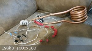
Oh.
|
|
|
CRUSTY
Hazard to Others
  
Posts: 138
Registered: 5-6-2016
Location: Nearby
Member Is Offline
Mood: High-Order
|
|
You're very welcome! I'm also really jealous that you have a ZVS induction setup, I've always wanted to make one. How difficult was it to get
functional?
[Edited on 16-7-2016 by CRUSTY]
|
|
|
SupaVillain
Hazard to Others
  
Posts: 171
Registered: 28-10-2014
Member Is Offline
Mood: No Mood
|
|
Haha I don't know about functional yet.... mostly the soldering to the copper chiller was the worst. Decided to weave bare wires into holes and solder
them in that way. Was really frustrated with trying to solder the caps to the 16 gauge wire, so I went with 26 gauge since it's about the same size as
the leads of the caps. I figured if leads could handle higher current then it must be fine to use smaller wire. Made my own inductors by filling
spools with ferrite powder and tons of electrical tape. Also probably burnt up an IRFP250 mosfet so I switched it out. I haven't gotten too much
practice soldering. I coiled the chiller on a bottle of Ciroc but got some kinks in it.
I'm actually a little confused with the above equation of PV = nRT.... I'm thinking since it's a compound, shouldn't I find the moles of the fluorine
content in CoF3 and not that of both the fluorine and the cobalt in the compound? Because for me it says that I'll get 3 liters of fluorine from just
5 grams of CoF3. I don't think the entire laser will even make up 1 liter. So that would supply me with like a thousand times what I need, being that
the fluorine content would be a just below less than a tenth of 1% of the gases, at 3 atm pressure inside.
600C = 873.15K
(1 atm)x = (0.04313 mol CoF3)(0.08206)(873.15 degrees K)
X = 3.09 liters
Oh geez, forgot what I was doing but I read this pageI came across the 2nd stage bronze cylinder already madeat this link or maybe slightly larger, and I think 3 inch copper pipe is suitable for the 1st stage since it's so much lower than the others, and
something clicked and I realized the 3 inch aluminum stock I might use on the rotor shaft is perfect for the 1st stage piston. It might be too early
to say that I wont need to do any lathing, but it is a possibility and would save so much time.
[Edited on 17-7-2016 by SupaVillain]
Oh.
|
|
|
DoctorOfPhilosophy
Hazard to Others
  
Posts: 130
Registered: 12-6-2012
Location: Ontario, Canada
Member Is Offline
Mood: enthralled
|
|
SupaVillain, thank you for posting your progress, looking forward to your next updates 
|
|
|
SupaVillain
Hazard to Others
  
Posts: 171
Registered: 28-10-2014
Member Is Offline
Mood: No Mood
|
|
After debating different methods of heating the CoF3 to 600C, I realized a torch, induction, laser through the optics, etc. are all too destructive
and too large near joints, tried thinking of powdering the anode so that the voltage would vaporize it, then thought of a tiny heating coil, and
tungsten wire filaments.
There are $8 dollar tungsten filament bulbs that could be placed in a tiny cup of CoF3, at the bottom of a small copper stubout....Actually I might
have to check chemical compatibility.... but a copper wire would work too, would just have to actually calculate current capacity and make sure it
doesnt melt the wire.
Also tried soldering with a butane torch unsuccesfully and realized since I'm using a Krytox covered epoxy on multiple things already, might as well
do so on two or three more instead of getting a torch.
Oh.
|
|
|
CRUSTY
Hazard to Others
  
Posts: 138
Registered: 5-6-2016
Location: Nearby
Member Is Offline
Mood: High-Order
|
|
You might want to be careful using copper. The CoF3 won't react with the copper at STP, but at about 400 degrees Celsius, fluorine will react with
copper to form copper (II) fluoride. Tungsten does the same (exothermically by the way) at 350-400 degrees Celsius, so make sure any copper and/or
tungsten is isolated from any F2 gas, since you're planning on using temperatures around 600C.
|
|
|
SupaVillain
Hazard to Others
  
Posts: 171
Registered: 28-10-2014
Member Is Offline
Mood: No Mood
|
|
Thanks again Crusty, I see that, I'm looking at pure nickel wire now and it doesn't seem to have problems. More on that below... The reason why it
wouldn't bother the rest of the copper is that this would be ideally a very small filament, probably wouldn't be operating the laser with this
filament heated up.
According to Haendler, Patterson, and Bernard (1952), in "The Reaction of Fluorine with Zinc, Nickel and Some of their Binary Compounds. Some
Properties of Zinc and Nickel Fluorides1a, 1b",
"The reaction of Fluorine with Nickel and Some of its Copmounds.--Finely divided nickel waqs fluorinated for purposes of comparison. It was
only partially reacted at 400 degrees. It was possible to approach complete conversion by the fluorinations at 550 degrees, the sample being ground
between runs."
J. Am. Chem. Soc., 1952, 74 (12), pp 3167–3168
DOI: 10.1021/ja01132a062
So what I take from this is that nickel should be fine for a one time heating, making the tiniest little amount of fluorine generated, could only be a
problem if the CoF3 powder keeps reabsorbing the fluorine after it returns to CoF2, resulting in the need of further heating events. I doubt that will
happen as the fluorine will likely be too dispersed across the inside of the copper piping. I'm also assuming their degrees are in Celsius. I could
always just valve off this area containing a heating coil and CoF3, which I will probably have to as the volume has been minimized as much as
possible.
Uh oh, turns out the eBay seller that had the thick viton I needed for my piston gaskets is "away" and nobody else I'm aware of sells them at the
thickness I might need for a non-astronomical price. Just in case I need it, I'm going to leave this here.... http://www.fluoroconsultants.com/sitebuildercontent/sitebuil...
Material: FPM/FKM (Fluorocarbon [Chlorotrifluoroethylenevinylidene fluoride])
Tradenames: Viton,[19] Tecnoflon FKM, DAI-EL (Daikin)
https://en.wikipedia.org/wiki/Fluoropolymer
Aaaaaaaaaand i researched that issue finding that "vulcanizing" is how parts can be joined (and with epoxy) and that compression molding is how theyre
totally reshaped.
[Edited on 20-7-2016 by SupaVillain]
Oh.
|
|
|
Fleaker
International Hazard
    
Posts: 1252
Registered: 19-6-2005
Member Is Offline
Mood: nucleophilic
|
|
Sounds like a fun project.
I still have some Krytox 240 AC that I would donate to the cause (had about 300 tubes but sold most, kept a few of tubes for firearms and greasing
things for aqua regia duty). I also have some FEP tubing and some PTFE manifolds if you're interested. If the F2 won't be under significant pressure,
you could probably get some PTFE or nickel 200 ferrules/nuts from swagelok and screw into the manifold.
as for the F2...why don't you just order it?
If you put down a deposit, I have a monel regulator that can be loaned to the cause.
"There are $8 dollar tungsten filament bulbs that could be placed in a tiny cup of CoF3, at the bottom of a small copper stubout....Actually I might
have to check chemical compatibility.... but a copper wire would work too, would just have to actually calculate current capacity and make sure it
doesnt melt the wire."
You'll get WF6 and scavenge all of your F2. Forget platinum too, same issue (know that from experience, PtF6 is volatile!).
As for vacuum pumps...I have something like this:
https://www.agilent.com/en-us/products/vacuum-technologies/p...
that I believe is loaded with Fomblin or Krytox pump oil. It and its sister pumps came out of a reactive gas plasma etching system.
EDIT:
Guess I should read more carefully--you already got the Krytox!
[Edited on 22-7-2016 by Fleaker]
Neither flask nor beaker.
"Kid, you don't even know just what you don't know. "
--The Dark Lord Sauron
|
|
|
SupaVillain
Hazard to Others
  
Posts: 171
Registered: 28-10-2014
Member Is Offline
Mood: No Mood
|
|
The best help is knowledge really, thank you for the support. How well does FEP tubing hold up against fluorine? I mean this laser will be at around 3
atmospheres and 150 degrees fahrenheit I believe, due to the discharge. I'm gonna get CoF3 instead of straight fluorine gas because of the difficulty
of handling the actual gas, this way I'll never have to actually handle the gas outside of a totally encapsulating closed chamber. I can also more
safely store that for longer periods of time, CoF2 can reabsorb the fluorine, and I think ordering fluorine in that form would be impossible in the
super tiny "easily made harmless" amounts that I actually need, I don't want to waste my country's surveillance resources on it when I'm just a dude
trying to make a special "light bulb". It's so dangerous I wouldn't even go anywhere near a cylinder of fluorine unless I had full positive pressure
and SCBA equipment. Ordering more than you need of anything is a terribly costly mistake, not only for the increased cost of proper disposal, but also
for the heightened danger in the event of catastrophe/spillage/leakage, and just the space it takes up even. I'm deciding soon whether to use nickel
foil or a nickel plated...anything, to hold the CoF3. Now i'm worrying that the current of a battery would enter foil and burn it up or take up the
current on contact with the nichrome instead of allowing the nichrome to heat up.
I have left a neodymium magnet stuck to a soldering iron set at 150 fahrenheit temperature for at least a half hour, finding that it doesn't lose its
strength. Covered ground on ideas for a DIY, slightly over 6" inch ball bearing today for the swash plate, and take a look at the size relationship of
the pistons and cylinders! With 1/16" difference, they share a little of 3/4's of a millimeter on each side, perfect AFAIK for the viton compression
rings and rider rings. I don't have the 1st stage cylinder yet... Also have to sand out a weld seam for the stainless 3rd stage cylinder. Going to
glue together a viton bladed fan as final decision. Krytox will really be what keeps the fluorine from destroying everything structurally.
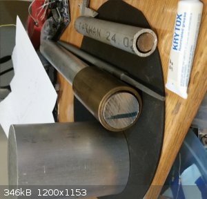
I have now obtained nickel thumbtacks that form a little bowl in the half inch pipe and I have calculated an example to picture the powder.
0.0618 liters F2 via 1/10th gram cof3 and thats 0.0257 ml volume of cof3 powder
[Edited on 23-7-2016 by SupaVillain]
Oh.
|
|
|
Fleaker
International Hazard
    
Posts: 1252
Registered: 19-6-2005
Member Is Offline
Mood: nucleophilic
|
|
If it's at 3 atm, I wouldn't trust it for delivery. Low pressure, room temp, it's fine.
Thing about fluorine is it's really really bad when it's moving, and it's under pressure, and it's hot.
Neither flask nor beaker.
"Kid, you don't even know just what you don't know. "
--The Dark Lord Sauron
|
|
|
| Pages:
1
2
3 |