Magpie
lab constructor

Posts: 5939
Registered: 1-11-2003
Location: USA
Member Is Offline
Mood: Chemistry: the subtle science.
|
|
difficult soldering job
I'm assembling a breadboard circuit to test a component for my stepper motor overhead mixers. To do this I have to place a 1nF capacitor in the
circuit. I can barely see this thing let alone solder it into the circuit. It is flat and is about 1mm x 2mm.
Can anyone tell me how to do this?
The single most important condition for a successful synthesis is good mixing - Nicodem
|
|
|
Twospoons
International Hazard
Posts: 1282
Registered: 26-7-2004
Location: Middle Earth
Member Is Offline
Mood: A trace of hope...
|
|
I trust you have a fine tip soldering iron? And fine solder? And by 'breadboard' I assume you mean one of those plug in strip boards?
So you want leads for your capacitor. I suggest you take a length of solid tinned copper wire and bend it into a hairpin. Put the capacitor between
the legs of the hairpin. Solder very carefully - tweezers and a magnifier are almost essential kit. now cut the loop of the hair pin and you should be
good to go.
Me, I'd normally make a PCB for this sort of thing - breadboard and SMT are not good companions.
Could you not find a 1nF leaded capacitor?
Helicopter: "helico" -> spiral, "pter" -> with wings
|
|
|
aga
Forum Drunkard
Posts: 7030
Registered: 25-3-2014
Member Is Offline
|
|
Sounds like you have an 0805 packaged surface-mount component.
They are so small they will fly away if you sneeze.
It is possible to solder wires to them, but not worth the effort/frustration - they are designed to be placed and soldered by machines, not humans.
You can buy ceramic disc capacitors of the 'normal' type which are much easier to handle/solder as they are about 10mm in diameter and have 1 inch
wire legs, perfect for a breadboard.
Edit:-
http://uk.farnell.com/multicomp/mcbu5102k5/cap-mlcc-y5p-1nf-...
i guess you got one that looks like this (under a microscope !) :-
http://uk.farnell.com/vishay/vj0805y102kxbbc31x/capacitor-ml...
[Edited on 5-11-2017 by aga]
|
|
|
Magpie
lab constructor
Posts: 5939
Registered: 1-11-2003
Location: USA
Member Is Offline
Mood: Chemistry: the subtle science.
|
|
Thanks for the nice direction Twospoons. I decided to order one that has leads.
The single most important condition for a successful synthesis is good mixing - Nicodem
|
|
|
mr.crow
National Hazard
Posts: 884
Registered: 9-9-2009
Location: Canada
Member Is Offline
Mood: 0xFF
|
|
0805 and 0603 aren't that bad. For breadboard its kind of handy to save space, like resistors for LEDs
1) Melt a small amount of solder on one of the pads
2) Use tweezers to pick up the component, melt the solder and stick it on. The joint will be ugly due to lack of flux but thats OK
3) Solder the other side, let it solidify then re-solder the first side
You need a good quality soldering station plus some nice lead solder
Double, double toil and trouble; Fire burn, and caldron bubble
|
|
|
Twospoons
International Hazard
Posts: 1282
Registered: 26-7-2004
Location: Middle Earth
Member Is Offline
Mood: A trace of hope...
|
|
If you are doing a bit of breadboarding, a nice thing to have is a mixed bag of capacitors, and one of resistors too. $10 will usually get you about
100 caps, or 300 resistors. Usually at least 5 of each value over a range. By the time you factor in shipping it works out quite well vs only buying
what you need.
Helicopter: "helico" -> spiral, "pter" -> with wings
|
|
|
violet sin
International Hazard
Posts: 1475
Registered: 2-9-2012
Location: Daydreaming of uraninite...
Member Is Offline
Mood: Good
|
|
I have done surface mount LED's and capacitors by the method twospoons suggests. But of course I had to devise it my self after the shortcomings of
my first two attempts and burnt finger tips. Lesson 1, soldering one side and then the other does not work. Too small of a work piece. Soldering
the second side removes the first. Lesson 2, pre cutting the wire like chopsticks taped together was hard to do because of solder surface tension,
pull off easy. Leads deform easy while applying the holding force to chopstick configuration, at least with thin wire.
Bend enameled wire in u, burn it or preferentially twist a diamond file inside the u shape, place the piece and solder, snip off extra. With LED's
one leg can be longer of course, but tape or twist leads so they don't break off from strain in storage.
I found some already made on eBay, they were enamel dipped ceramic capacitors with stubby leads, super cheap too. They looked to be smc cube like
shape under enamel. Great for breadboard.
The mixed bags are a solid idea, one each of ceramic/electrolytic caps and some resistors is practically a must unless you enjoy burning fingertips
while removing parts from dead or sacrificial electronics. But hey, never too good to get me hands dirty, just a big hassle. Still happen on
numerous occasions
Electronics are fun and confusing like chem 
****************************************************************************
**********************************Additional info***************************
I was specifically soldering the smallest LED's I could get to small enameled wire... For an art project/gift. Made at least 10x of each
color(r-o-y-g-b-v) and a couple UV guys as well.
Pinched a few SMC caps and did the same b/c radio shack is a ripoff for small components and Chinese suppliers take ~3 weeks. On the fly improv, at
its best.
There is no problem doing so to a pcb. They are minor nuisance there.
[Edited on 7-11-2017 by violet sin]
|
|
|
highpower48
Hazard to Self
Posts: 98
Registered: 30-10-2014
Member Is Offline
Mood: No Mood
|
|
I do a lot of electronics, which means I also do tons of soldering. To do surface mount components while not easy is doable. You will need either
solder paste or fine .03 Rosen core solder, a good hands free magnifier, tweezers, flux pen, and a fine tipped soldering iron. Start by tinning your
soldering iron, then tin your solder pad on your work piece, dab on some flux on the tinned solder pad. Take the tweezers and grab hold of the
component and place on the tinned and fluxed solder pad. Hold down the component with the tweezers in the middle, using the tips of the tweezers.
Apply heat to the component leads, you will feel a slight downward shift of the component when the solder melts. Repeat on opposite component lead.
Keep downward pressure on middle of component to keep it from shifting if you other lead also results. Let solder solidify, remove tweezers. This is
harder to explain than to do. If you have holes in your circuit board for through hole component than that is the way to go.
|
|
|
Magpie
lab constructor
Posts: 5939
Registered: 1-11-2003
Location: USA
Member Is Offline
Mood: Chemistry: the subtle science.
|
|
I am not an expert in electronics but 1nF seems like an extremely small amount of capacitance.
Since capacitor is so small why not embed it in something large that would have regular leads? I guess this is what has been done with the new
capacitor I have on order.
I also thought that since the capacitance is so small could I substitute a piece of wire that is not too conductive?
The single most important condition for a successful synthesis is good mixing - Nicodem
|
|
|
highpower48
Hazard to Self
Posts: 98
Registered: 30-10-2014
Member Is Offline
Mood: No Mood
|
|
The 1nf cap most likely is being used to
help reduce noise, you can try just using a jumper and see what will happen. It's not going to hurt anything.
|
|
|
aga
Forum Drunkard
Posts: 7030
Registered: 25-3-2014
Member Is Offline
|
|
Would it be possible to see the circuit diagram ?
It's almost impossible to judge whether the capacitor is required or not without the whole picture.
While 1nF sounds like a really small value, it can make all the difference.
In electronics 100 Farad thru to 1 pico Farad can be required, depending on what it is supposed to be doing.
If it is for decoupling then a piece of high-resistance wire (aka a Resistor !) will not work at all, neither will a jumper.
|
|
|
Magpie
lab constructor
Posts: 5939
Registered: 1-11-2003
Location: USA
Member Is Offline
Mood: Chemistry: the subtle science.
|
|
Yes, here is the circuit:
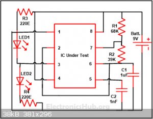
The IC being tested is a 555 timer.
[Edited on 7-11-2017 by Magpie]
The single most important condition for a successful synthesis is good mixing - Nicodem
|
|
|
Twospoons
International Hazard
Posts: 1282
Registered: 26-7-2004
Location: Middle Earth
Member Is Offline
Mood: A trace of hope...
|
|
Yeah, the 1nf isn't really needed. You can just leave that pin open.
Helicopter: "helico" -> spiral, "pter" -> with wings
|
|
|
highpower48
Hazard to Self
Posts: 98
Registered: 30-10-2014
Member Is Offline
Mood: No Mood
|
|
Yes pin 5 (control voltage) can be left open or float. Normally I ground any unused pins, but use a 10nf cap and not a 1nf.
|
|
|
Twospoons
International Hazard
Posts: 1282
Registered: 26-7-2004
Location: Middle Earth
Member Is Offline
Mood: A trace of hope...
|
|
That depends very much on what you are doing.
In power electronics it would be small. In amplifiers and small signal applications it would be typical. In RF it would be large. In silicon chip
designs it would be enormous (I have seen the circuit of an image sensor where the integration capacitors were 30fF - as in 10-15 farads!)
In the 555 circuit the 1nF is filtering for an internal threshold voltage - it works fine without it, but there will be a little bit more jitter on
the output waveform, depending on how good the power supply is.
[Edited on 7-11-2017 by Twospoons]
[Edited on 7-11-2017 by Twospoons]
Helicopter: "helico" -> spiral, "pter" -> with wings
|
|
|
aga
Forum Drunkard
Posts: 7030
Registered: 25-3-2014
Member Is Offline
|
|
Can't remember ever having connected pin 5 on a 555 type IC to anything, ever.
Internal to the chip, it is a point in a voltage divider chain, comprising 3 resistors from 0v to Vcc, on the 'high' side.
A capacitor there will reduce noise a bit, but this is just a very simple timer/oscillator chip, so if you really really needed pinpoint accuracy it
would not be the right chip.
Edit:
To be fair, the 555 has been around forever due to it's reliability and robustness, so don't ditch it in favour of a PIC or AVR.
[Edited on 7-11-2017 by aga]
|
|
|
Magpie
lab constructor
Posts: 5939
Registered: 1-11-2003
Location: USA
Member Is Offline
Mood: Chemistry: the subtle science.
|
|
Thanks, everyone. I had no idea we had so many knowledgeable in electronics.
I activated the circuit with a 9v battery and the LEDs did not come on. Therefore I conclude that the 555 is defective. This IC came in a packet of
10. All 10 are apparently defective.
The single most important condition for a successful synthesis is good mixing - Nicodem
|
|
|
The Volatile Chemist
International Hazard
Posts: 1981
Registered: 22-3-2014
Location: 'Stil' in the lab...
Member Is Offline
Mood: Copious
|
|
That's disappointing...I know I've fried a 555 before, it's disappointing to loose such a useful IC - let alone have 10 defective ones!
|
|
|
Twospoons
International Hazard
Posts: 1282
Registered: 26-7-2004
Location: Middle Earth
Member Is Offline
Mood: A trace of hope...
|
|
I would expect either both or one LED to be on in the case on a defective chip. Unless its shorting out the supply. Did anything get hot? I'm
surprised you have 10 chips DOA, unless they're fakes. Source?
Helicopter: "helico" -> spiral, "pter" -> with wings
|
|
|
Melgar
Anti-Spam Agent
Posts: 2004
Registered: 23-2-2010
Location: Connecticut
Member Is Offline
Mood: Estrified
|
|
If all ten ICs are defective, that's usually a sign that the first time I tested them, I royally fucked up the testing circuit and burnt them all out
when doing the testing.
You could just drop $6 on an arduino, and spend your time programming various stirring cycles. That's what I've been doing with mine.
The first step in the process of learning something is admitting that you don't know it already.
I'm givin' the spam shields max power at full warp, but they just dinna have the power! We're gonna have to evacuate to new forum software!
|
|
|
Fulmen
International Hazard
Posts: 1693
Registered: 24-9-2005
Member Is Offline
Mood: Bored
|
|
I agree, it's not very likely that all 10 chips are dead unless they are fake or you killed them. The leads should light up unless the chip is
shorting the battery.
Start by redoing the circuit from scratch. Also, it's not a bad idea to add a current limiting resistor in series with the battery. This reduces the
risk of frying components.
We're not banging rocks together here. We know how to put a man back together.
|
|
|
Magpie
lab constructor
Posts: 5939
Registered: 1-11-2003
Location: USA
Member Is Offline
Mood: Chemistry: the subtle science.
|
|
In agreement with logic and common sense the 555 IC is not bad. I had two failed LEDs in the circuit. When I replaced these the
LEDs pulsed as expected, even without the 1nF capacitor. Thanks for all your help.
The single most important condition for a successful synthesis is good mixing - Nicodem
|
|
|
LD5050
Hazard to Others
Posts: 182
Registered: 16-1-2017
Member Is Offline
Mood: No Mood
|
|
I don't know much about this but look in fluorocarbons FC40 in particular. Supposedly if you put this stuff in a beaker and boil it the fumes are very
heavy and stay inside the beaker and are very hot. It is used for soldering difficult parts on circuit boards. All you do is dip the circuit board in
the fumes with the piece you want to solder and the flux and solder itself and the heat from the fumes solders it in place.
|
|
|
Twospoons
International Hazard
Posts: 1282
Registered: 26-7-2004
Location: Middle Earth
Member Is Offline
Mood: A trace of hope...
|
|
You're talking about vapor phase reflow soldering - not really something for the home lab. Hot air works just as well in a lab situation, and hot-air
rework stations can be had for about a hundred bucks. I bought one out of china that included an IR pre-heater and soldering pencil too. Or you could
buy a cheap toaster oven for IR reflow - that works pretty well too.
[Edited on 9-11-2017 by Twospoons]
Helicopter: "helico" -> spiral, "pter" -> with wings
|
|
|


