Luc
Harmless

Posts: 5
Registered: 23-12-2017
Member Is Offline
Mood: No Mood
|
|
Need help on reading FeSO4 voltammograms
Hi all,
Since this is my first post on the forum I would like to briefly introduce myself. I did learn chemistry at college and got a master degree in
chemical engineering but I ended up working as an optical engineer (don't ask me why). In my free time I still enjoy doing some chemistry but usualy
more focused towards engineering. I try to systematically report my experiments on my website, just in case other people would be enjoying the same
technical issues as I did. I have some posts on optics, electronics and chemistry. If you are interrested you can have a short look at http://www.thepulsar.be/archives/. I am reporting all these experiments for amateur just like people on this forum so I hope some of you may find
interrest in it :-)
In this DIY context I have been struggling these last few months on an electrochemistry project. I have developped an Arduino board to record
voltammograms using pulse methods. I implement several experimental protocols including square wave voltammetry, sampled current voltammetry, normal
pulse voltammetry and differential pulse voltammetry from the descriptions of BASi website. I have checked the waveforms on the oscilloscope and they look just fine. So I am now trying to actually make some experiments with
it. And that is where everything falls apart...
My electrochemical cell is fairly simple : two carbon electrodes that I polish with fine sandpaper and wash with demineralized water before each
experiment and disposable Ag/AgCl reference electrode made from an Ag wire oxidized in bleach then cleaned with dem. water and placed in a silicon
(Versilic) plastic tube filled with commercial electrode KCl solution and ended with a molecular sieve bead as junction. The electrode seems to be
working properly with a rest potential that looks correct when compared to a Cu wire dipped into 1M CuCl2 solution.
Despite all of that, I never managed to record voltammograms that I could make sense of! KI solution was a failure (it dissolved my gold electrode...
which is why I swapped to carbon) and SnCl2 solution only gave something at the first scan and flat after (I suppose that I formed hydroxide which
made the Sn++ unavailable for the successive scans). To prevent all of these issues I decided to go for a FeSO4 solution with a few drops of 30% HCl.
The FeSO4 was technical grade and the HCl was from DIY stores, so probably full of impurities.
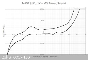
This time I got something  The sampled current voltammogram is given below: The sampled current voltammogram is given below:

I do get some nice peaks that differs from the scan direction.
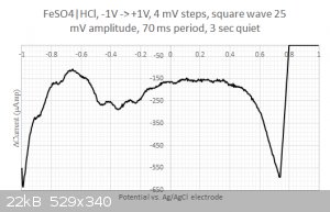
Moreover, when running square wave voltammetry from -1V to +1V I do resolve some structure in the large -0.2...0.4 Volts blob:

One could think that I would be happy with these results but I am not.
My experimental results have so many peaks that it is hard to read them; they are in fact much more complex than the easy examples I can find in
textbooks. Also, my textbook (Electrochemistry: principles, methods and applications) is quite eager on details about pulse methods, which does not
help. I have looked on the Internet but without much success apart for protocols involving chemicals that I don't have (or ultrapure analytical
grade).
So I am desperetely looking for someone would could help me reading those data and tell me if they make sense or not. To make things easier, I would
like to ask the following questions:
1/ Are there any easier electrochemical reactions that I could monitor ? Apparently, FeSO4 was not the smartest choice... Most textbooks introduce
square wave voltammetry by separating different metal cations. Do you have a complete protocol (potential ranges, pH, sweep rate...) that would give
easier-to-read voltammograms and still enjoy the fun of doing electrochemistry ? Simply working with Cu2+ or Sn2+ was unfortunately a failure with
clear deposits of hydroxide in the case of copper and probably the same with the tin.
2/ What are those peaks in the -0.2...0.4 Volts range ? Is that coming from the iron or from the sulfate ? I have checked with the redox table but I
cannot find any matches... Same for the two other peaks at 0.2 and 0.45 Volts. Are my axis eventually flipped around ? I have four different
combination with the reference electrode and I do not know which one could be the correct one (i.e. signal + ref, signal - ref, -signal + ref, -signal
- ref). I was expecting to get the answer to that question by looking at a "simple" voltammogram but... yeah... that's not really the case :-/
3/ How the hell do you clean up the hundreds of entries of the redox tables ? For instance, I doubt that I would record anything for Fe3+ + 3 e−
⇌ Fe(s) at 0.04 V, right ? I would expect to see Fe3+ -> Fe2+ and Fe2+ -> Fe but how can I be sure about that ?
Big thanks anyway to any of you who could make this whole thing more easy to understand! Feel free to post partial replies as well  I can perform additionnal experiments if you need more inputs. I can perform additionnal experiments if you need more inputs.
|
|
|
Metacelsus
International Hazard
Posts: 2531
Registered: 26-12-2012
Location: Boston, MA
Member Is Offline
Mood: Double, double, toil and trouble
|
|
This paper might be helpful for you:
Attachment: MN.JPCC.117(2013)16343.pdf (1.3MB)
This file has been downloaded 338 times
| Quote: | | Figure 2b shows a CV spectrum measured at a scanning rate of 5 mV/s. The reduction of Fe(III) ions to Fe(II) ions occurs as a single peak at 0.35 V,
which is close to that obtained at 20 mV/s. The oxidation of Fe(II) ions to Fe(III) ions shows two peaks, whose positions are 0.57 and 0.72 V. The
peak at 0.72 V is close to that obtained at 20 mV/s and is attributed to simple oxidation of Fe(II) to Fe(III). The oxidation process at the low
potential involves the sulfate ions, which affect electrode kinetic parameters and diffusion coefficients at high concentration of aqueous iron
sulfate solutions. |
[Edited on 12-23-2017 by Metacelsus]
|
|
|
NEMO-Chemistry
International Hazard
Posts: 1559
Registered: 29-5-2016
Location: UK
Member Is Offline
Mood: No Mood
|
|
This is way out of my league, but a couple of things you likely know already. With any chip its best to multi sample and then average the result, are
you doing this? I think your going to have to bite the bullet and buy a small amount of expensive super pure stuff you have a graph for and use that
to tune your system.
Using impure reagent grade chemicals wont help you in setting up, apart from anything else you cant get a baseline you are confident about. Have you
tried contacting a university or even a chemical company and begging a small sample of pure chemical? if you explain what your doing you might get a
pleasant surprise. very cool project thx for sharing.
OFF TOPIC
On your site you pic based RS232
A couple of small points on this, most people now use RS232 to usb cables as most pc's dont have native serial ports, with these cables you no longer
need MAX232 chips from the pic to the cable..
JFI
[Edited on 26-12-2017 by NEMO-Chemistry]
|
|
|
Luc
Harmless
Posts: 5
Registered: 23-12-2017
Member Is Offline
Mood: No Mood
|
|
I have performed more experiments today with ultra-diluted CuCl2/HCl and the results are crappy with tons of those ripples. So I probably have an
issue with either the electrode that I'm using or the water that may contains lots of impurities as well.
I'm a bit annoyed with using/buying top-notch grade quality chemicals because the overall idea was to allow the amateur scientist to conduct
qualitative analysis of samples in a DIY way. If people need to use ultra pure chemicals that kills most of the DIY concept.
Maybe I can try to get in touch with electrochemists at the unniversity, there might still be some people I know working there. That would at least
allow me to check the circuit by putting the electrodes/chemicals reaction apart.
@Nemo: I implemented your advice of multi-sampling this morning. It is a bit tricky because of the non-steady nature of the waveforms considering the
relatively low speed of the Arduino ADC. Nonetheless, it should at least give repeatable measurements even if they might be biased. On the other hand,
the 10-bit ADC starts to be limiting with the quantification noise. Maybe upgrading to 12-bit ADC would be a good thing.
Last time I forgot to put a picture of the arduino shield, so I am also taking the occasion to put one

I will post an article soon on my website about it but I really want to have at least some basic voltammetric profile to show.
|
|
|
|


