| Pages:
1
2
3
4
5 |
unionised
International Hazard

Posts: 5102
Registered: 1-11-2003
Location: UK
Member Is Offline
Mood: No Mood
|
|
"No moths on my balls. "Glad to hear it.
Anyway, none of the "big boys' toys" really addresses the topic; they are hardly DIY.
As has been mentioned, the tricky bit is getting enough energy into the "projectile". A V de G will give you practically unlimited voltage if you have
the balls for it (if you will forgive the expression) but you could always look at cyclotron type accelerators.
|
|
|
Sauron
International Hazard
Posts: 5351
Registered: 22-12-2006
Location: Barad-Dur, Mordor
Member Is Offline
Mood: metastable
|
|
If I were after nuclear interactions I'd have little choice. But I'm just interested in chemical reactions (like free radical production) and so 500
KV to 1 MV and 50-100 microamps is plenty. Cockcroft and Walton made do with 150 KV to 700 KV and they were doing transmutations (albeit really
miniscule ones that they could only detect by scintillation counting.)
In reading about what the Big Boys are doing I am somewhat disheartened at the utter insignificance of such a setup as I have in mind, even in
Thailand they had a major accelerator at Chiang Mai at the Fast Neuiron lab. Serious electron beams are merely technology for welding, evaporation,
etc. Even more serious electron beams are input for free electron lasers. Or injectors for synchrotrons. So what I am doing is like a caveman rubbing
two sticks together standing next to a guy with a plasma arc welder. No Can Compete!
------------
Actually I ought to eat those words. In the 1940s a group of high school kids in El Cerrito CA (a suburb of Berkeley) decided to build a small
cyclotron. They got technical advice from the Rad Lab at UC Berkeley (Lawrence's lab), they got financial support from the school and the school
district, it took them 2 years and they DID it. A 1000 lb magnet, 800 lbs of magnet wire, a working 6" cyclotron putting out a 7 microamp proton beam.
I am in awe. They worked with high voltages and currents of very lethal proportions on equipment they built themselves. All this was detailed in a
1953 The Amateur Scientist article (before C.T.Stong's tenure) which I will post here.
Stong actually revisited the subject of VDG-powered DIY particle accelerators that he and Frank Lee wrote about in the same SA column in 1957. Stong
wrote another column in 1971 about a different homemade accelerator, this one for protons and deuterons, but using a Frank Lee (Morris and Lee, now
Science First) 500 KV VDG. The accelerator tube is quite different from the one described 14 years earlier, and naturally the source is different as
well. I will also post this article here.
The Bell Jar is a quarterly publication devoted to vacuum science published by Steve Hansen in New Hampshire. Many of the articles from this fine
periodical are available online, and anyone interested in medium to high vacuum will benefit from checking this out. Frank Lee has some recollections
published there, and there's an article about vacuum and The Amateur Scientist column under Stong.
Of particular interest to me is an article on how to achieve hard vacuum without diffusion pump, using a two stage mechanical oil sealed pump and a
special zeolite trap to remove water vapor and back-diffusing oil vapor. Diffusion pumps are costly and require a roughing pump anyway so this
technique will be a good one for me in my accelerator tube work.
While the homemade tubes described by Stong relied on vacuum wax for sealing and assembly, I prefer to put my faith in kovar or copper graded seals
that are professionally done by glassblowers who know how to produce glass to metal and metal to metal seals and joints that are vacuum tight to 10x-5
torr.
[Edited on 7-3-2007 by Sauron]
Attachment: http___vacuum.ramapo.edu_physics_physics-doc_amsci_AmSci01_1953_09_1953-09-fs.zip (374kB)
This file has been downloaded 1306 times
|
|
|
jtkelectroman
Harmless
Posts: 31
Registered: 13-3-2007
Location: The Great USA
Member Is Offline
Mood: No Mood
|
|
cyclotron
For starters I would say Hi this the first time I have replied to this board but I have visited it many times before.
Now I saw this thread and I thought I would take the time to say that since august of 2003 I have been building my own Cyclotron with some help from
the staff over at St.Cloud state but keep in mind that I am the sole funder of this project and it was my Idea to start it.
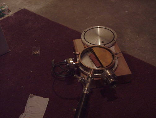
So far I have mannaged to build the cyclotron cavity as can be seen in the picture below. I have also nearly completed the UHV system but I still need
a mechanical vacuum pump and foreline filters.
The gas handeling system is complete minus pressure guages.
I have also aquired a 19"W by 56" tall rack mount type cart and I have begun installing the cyclotrons controll systems. I have allready installed an
ion beam current meter, a kepco DC power supply for the ion source, and an Rf frequency generator. I also was offered a 1500 watt Vicor MegaPack power
supply from Timension Inc.
I also have several Ionization guages but no controllers for them.
I also aquired a small compact Varian Ion implantation magnet which I plan on refurbishing so that it will create a magnetic field somewhere arround
1.2T.
Now as you may have guessed this equipment is very expensive even the second hand stuff and So I still need to find a way to come up with the funds
for the following equipment yet:
Cryotrap
High power RF Amplifier with 1Kv Ac p-p or higher
mechanical pump
Rf frequency counter
Large spool of magnet wire to make new 8" diameter coils/yolkes for the ion implantation magnet.
Two 7inch diameter pole faces for magnet
used ocilloscope 20Mhz or higher
Please visit my website and give me your input and if anyone has any old equipment lying around that they don't need that they wouldn't mind donating
for the cyclotron project please let me know.
[img]http://www.angelfire.com/weird2/chemistrymn/cyclotron_photo_album/index.album/cyclotron-cavity?i=1[/img]
|
|
|
jtkelectroman
Harmless
Posts: 31
Registered: 13-3-2007
Location: The Great USA
Member Is Offline
Mood: No Mood
|
|
Cyclotron Photo
Here hopefully the immage shows up. If it does here is a picture of the cyclotron cavity.
|
|
|
jtkelectroman
Harmless
Posts: 31
Registered: 13-3-2007
Location: The Great USA
Member Is Offline
Mood: No Mood
|
|
My website
Heres a link to my webpage.
http://www.angelfire.com/weird2/chemistrymn/cyclotron_photo_...
|
|
|
Maya
Hazard to Others
Posts: 263
Registered: 3-10-2006
Location: Mercury
Member Is Offline
Mood: molten
|
|
<<Cryotrap
1 High power RF Amplifier with 1Kv Ac p-p or higher
2 mechanical pump
3 Rf frequency counter
4 Large spool of magnet wire to make new 8" diameter coils/yolkes for the ion implantation magnet.
5 Two 7inch diameter pole faces for magnet
6 used ocilloscope 20Mhz or higher>>
# 1, 5 IDK about
but
# 2, 4, 6 I've picked up for under $100 ea at a famous action
# 3 I bet U could as well
# 4 actually I've picked up all made as from an x ray transformer secondary at least
10 inches across
Oh, I forgot the cryotrap,
I picked up one savant for $10, didn't work.
I picked up another for $49 which got down to -90 degrees
[Edited on 15-3-2007 by Maya]
\"Prefiero ser yo extranjero en otras patrias, a serlo en la mia\"
|
|
|
Sauron
International Hazard
Posts: 5351
Registered: 22-12-2006
Location: Barad-Dur, Mordor
Member Is Offline
Mood: metastable
|
|
Very ambitious!
I salute you.
HOWEVER your attachment or its host placed a popup on my PC which is likely to be malware. At least, the popup occured just after I opened your link.
It was a come on for some screensaver (ostensibly).
Members be warned.
Here is an illustration of a Coolidge cascade accelerator tube from a 1935 Physical Review article by Tuve et al, referenced below.
[Edited on 17-3-2007 by Sauron]
[Edited on 17-3-2007 by Sauron]
[Edited on 17-3-2007 by Sauron]

|
|
|
not_important
International Hazard
Posts: 3873
Registered: 21-7-2006
Member Is Offline
Mood: No Mood
|
|
www.angelfire.com
is warning enough. Don't go there using IE
|
|
|
Sauron
International Hazard
Posts: 5351
Registered: 22-12-2006
Location: Barad-Dur, Mordor
Member Is Offline
Mood: metastable
|
|
Here is the second C.L.Stong article in his Amateur Scientist column in Scientific American concerning DIY particle accelerators based on Van de
Graaff generator high voltage electrostatic supplies. This one was in 1971; the first was in 1957. Based on remarks made in the Bell Jar by Frank Lee
who supplied the VDGs for both projects Stong was the instigator of the first project so he could write about it.
While Lee's 1957 linear accelerator had a simple, single chamber partial tube with a thermionic electron source at the cathode and an uncollimated
electron beam, the tube in the 1971 article was a collimated, Coolidge-cascade type of multiple sections built around copper corona rings which also
served to support the copper electrostatic shields. Compare the Stong illustration with this detail from a 1935 paper in Physical Review by Tuve et al
detailing a cascade accelerator tube employed with a two meter VDG at the Carnegie Institute in Washington DC. The similarity is striking. The rounded
spun ends of the shields are to avoid cold-cathode effect. The unshielded gaps between the tubular shields are for collimation of the beam (in this
case, protons or deuterons) by the electrostatic charge of opposite polarity along the experior of the vacuum tube. In the case of this 1.25" OD tube
described by Stong the proton beam emerges with a diameter of about 1 mm and is made visible, for purposes of adjusting the ion source, by use of a
quartz target which fluoresces.
I also have Coolidge's first paper describing his accelerator tube and also the cascade version. Unlike the tube Stong describes, both Coolidge's
cascade sections and the Tuve tube at Carnegie have bulb sections at the unshielded regions. Stong's amateur designer omitted these for simplicity and
economy. His sections were fastened to the corona/shield assemblies by vacuum wax, a fragile method to say the least. I intend to have my sections
professionally blown and made with graded seals at each end that can be brazed or welded to the lathe turned copper pieces. Kovar and copper graded
seals are quite standard items in scientific glassblowing, the Kovar alloy being preferable because its thermal expansion coefficient is same as
Pyrex. (Coolidge in 1926 was using the Invar alloy for same reason.) The contractor will deliver a vacuum tight assembly to the specified 10x-5 torr.
The resulting tube will be a lot less temporary than the one described by Stong. Most likely this will be about a 1 m long tube of between 50 and 75
mm OD at the cylindrical sections and will be designed to be mounted between two 17" VDG spheres, one positively charged and the other negative, with
a total potential (unloaded) of 1 MV and an actual potential across the tube (which loads them) of 500 KV to 750 KV. I am hoping to be able to achieve
an electron beam energy of 100 microamps by employing high voltage DC charge spraying onto the VDG belts and using charge doublers to make the system
more efficient.
[
[Edited on 17-3-2007 by Sauron]
Attachment: http___vacuum.ramapo.edu_physics_physics-doc_amsci_AmSci01_1971_08_1971-08-fs.pdf (263kB)
This file has been downloaded 3591 times
|
|
|
jtkelectroman
Harmless
Posts: 31
Registered: 13-3-2007
Location: The Great USA
Member Is Offline
Mood: No Mood
|
|
| Quote: | Originally posted by Sauron
Very ambitious!
I salute you.
HOWEVER your attachment or its host placed a popup on my PC which is likely to be malware. At least, the popup occured just after I opened your link.
It was a come on for some screensaver (ostensibly).
Members be warned.
I seem to get popup adds from them too. I think it is because I am still using they're free webpage member ship I haven't upgraded the account to an
add free page yet. I plan on doing it once I get more stuff put on the page
[Edited on 16-3-2007 by Sauron] |
|
|
|
jtkelectroman
Harmless
Posts: 31
Registered: 13-3-2007
Location: The Great USA
Member Is Offline
Mood: No Mood
|
|
Yes you have to b quite ambitious to do something of this magnetude. I'll tell you one thing it was a pain in the arse trying braze weld 316 stainless
steel to copper metal.
|
|
|
Sauron
International Hazard
Posts: 5351
Registered: 22-12-2006
Location: Barad-Dur, Mordor
Member Is Offline
Mood: metastable
|
|
What is the diameter of the cyclotron (distance between the poles of the main magnet) and how much does your magnet weigh?
Are you familiar with the cyclotron that a group of high school boys in El Cerrito CA built in the mid 1940s? This was written up in Scientific
American in early 1950s, by which time one of the boys had graduated, went on to Berkeley and graduated from there and was hired by the Rad Lab there
as a researcher.
I am in midst of a large project that consumes most of my resources, and a number of smaller projects that get funded with leftovers, the VDG
accelerator is one of those. The big one is a peptide synthesis and a serious HPLC lab to suport it. So I am not about to mount a Herculean effort
like yours. But you have my respect, and you probably deserve the Hubris Award for the decade.
If you have not seen this I will post it.
Their cyclotron took two years to do and worked. If I recall, they achieved a beam current of 14 microamps. I think these teenagers had incredible
chutzpah - but they carried it off with panache. You apparently have the same daring-do, It's astonishing.
[Edited on 17-3-2007 by Sauron]
Attachment: http___vacuum.ramapo.edu_physics_physics-doc_amsci_AmSci01_1953_09_1953-09-fs.pdf (434kB)
This file has been downloaded 1109 times
|
|
|
jtkelectroman
Harmless
Posts: 31
Registered: 13-3-2007
Location: The Great USA
Member Is Offline
Mood: No Mood
|
|
The distance between the two pole faces will be about 2.5-3 inches when the magnet is finished being refurbished. The magnet that I have right now is
extremelly small in fact it is only 42 pounds with two pole faces that are about 2.5-3inches in diameter.
What I plan on doing is removing the two pole faces and replacing them with two larger pole faces that go from 2.5 inches to 7.5 inches in diameter.
This should give me enough room to add on two large approximately 8in diameter water cooled coils. If all goes well this set up should allow me to
design a small compact electromagnet that has an intense magnetic field in the center and the magneti field should decrease at the edges of the pole
faces. I plan on adding some shim coils to the unit too for magnetic field corrections.
"I am in midst of a large project that consumes most of my resources, and a number of smaller projects that get funded with leftovers, the VDG
accelerator is one of those. The big one is a peptide synthesis and a serious HPLC lab to suport it. So I am not about to mount a Herculean effort
like yours. But you have my respect, and you probably deserve the Hubris Award for the decade."
Peptide synthesis. Sounds cool. Hey I've been setting up a DNA analysis lab at my house . I've got all sorts of electrophoresis equipment,
transfection reagents, dyes and so on.
BTW Sauron thanks for posting the articles on the van de graaf acellerators I personally wouldn't mind building them once I finish the cyclotron in
fact I would like to use a van de graaf generator for building a tandem particle acellerator that is flushed with SF6. Also I found that the articles
you posted had interesting information on ionization guage circuits and thermocouple circuits. I think I will try to use this info for making my own
guage controllers this should save me alot of money.
Yes I am familiar with the high school students that built the cyclotron, what an interesting article.
| Quote: | Originally posted by Sauron
What is the diameter of the cyclotron (distance between the poles of the main magnet) and how much does your magnet weigh?
Are you familiar with the cyclotron that a group of high school boys in El Cerrito CA built in the mid 1940s? This was written up in Scientific
American in early 1950s, by which time one of the boys had graduated, went on to Berkeley and graduated from there and was hired by the Rad Lab there
as a researcher.
I am in midst of a large project that consumes most of my resources, and a number of smaller projects that get funded with leftovers, the VDG
accelerator is one of those. The big one is a peptide synthesis and a serious HPLC lab to suport it. So I am not about to mount a Herculean effort
like yours. But you have my respect, and you probably deserve the Hubris Award for the decade.
If you have not seen this I will post it.
Their cyclotron took two years to do and worked. If I recall, they achieved a beam current of 14 microamps. I think these teenagers had incredible
chutzpah - but they carried it off with panache. You apparently have the same daring-do, It's astonishing.
[Edited on 17-3-2007 by Sauron] |
|
|
|
Sauron
International Hazard
Posts: 5351
Registered: 22-12-2006
Location: Barad-Dur, Mordor
Member Is Offline
Mood: metastable
|
|
Here's enlarged image of the cascade LINAC tube in the SA article. Note strong similarity to the Carnegie (Tuve et al, PR, 1935) tube detailed above.
The general layout of the Carnegie 1 meter and 2 meter VDG based accelerators was also similar to what Stong described in his 1971 article and quite
different from Robert Van de Graaff's own early designs.
My own intention is to try to follow Van de Graaff's design for the general machine design but use the cascade tube, with improvements, based on the
later work.
[Edited on 17-3-2007 by Sauron]

|
|
|
Sauron
International Hazard
Posts: 5351
Registered: 22-12-2006
Location: Barad-Dur, Mordor
Member Is Offline
Mood: metastable
|
|
(I beg the forum's indulgence for this double post and apologise to Lord Vulture for the transgression.)
Hmmm. 42 lbs? The El Cerrito High School 6" cyclotron of mid 1940s had a 1000 lb mild steel magnet (they couldn't get soft Norwegian iron at the time)
and was too large to machine in-house, they talked a technical school in Oakland into machining it. Granted that with special alloys you might get
some improvement in the strength of field but, 42 lbs seems likely to be insufficient for the instrument's needs.
Recently we were looking at some NMRs on the market using surplus magnetron magnets and these were also hundreds of lbs. up to 1000 lbs mass of
magnet. So my question is, what is the basis of your design with such a small main magnet?
Regarding vacuum gauges of all types, I have a lot of information regarding circuit diagrams, DIY, commercial models of thermocouple gauges, Pirani
gauges etc. much better than what was in those three SA articles. Happy to pass it along to you.
[Edited on 17-3-2007 by Sauron]

|
|
|
12AX7
Post Harlot
Posts: 4803
Registered: 8-3-2005
Location: oscillating
Member Is Offline
Mood: informative
|
|
I wonder what the saturation, coercivity and permeability of mild steel (circa 1020, annealed), cast iron (ferritic, gray or ductile) and cast silicon
steel (not necessarily as available, but high saturation (~1.2T) suitable for 99% of all transformers in use today).
Tim
|
|
|
jpsmith123
National Hazard
Posts: 764
Registered: 24-6-2005
Member Is Offline
Mood: No Mood
|
|
I got a Varian #801 TC gauge on ebay, rather cheaply. Then I bought an enclosure for it at "Duniway Stock Room"...they call it a "TGC Box", for
$57.00.
Duniway actually sells all the parts. The two main items are the TC tube, and the meter. The power supply (a slightly adjustable current source), you
could easily build yourself, if you can't get a Varian #801 somewhere.
http://www.duniway.com/images/pdf/pg/p-85-controllers-new.pd...
As far as the tube, when I was toying with the idea of building one, I contacted a few places, e.g., "Larson Electronic Glass", but the prices were
higher than I could go, so I decided that I would try to solder the glass to the copper or brass electrodes using indium.
Lastly, for admitting small amounts of H2 or D2 into the tube, I got some thin-walled 1/8" dia. Pd-Ag alloy tubes with one closed end. I was going to
use the tubes as a combination electrolytic cathode/vacuum interface; IOW, I was hoping the Pd-Ag tubes would act as a controlled leak, with the
amount of gas admitted proportional to the electrolysis current.
|
|
|
Sauron
International Hazard
Posts: 5351
Registered: 22-12-2006
Location: Barad-Dur, Mordor
Member Is Offline
Mood: metastable
|
|
My own setup will strictly be for electron beam rather than proton beam, as I'm not interested in anything other than chemical reactions promoted by
such a beam. I posted the illos of the proton accelerator just for the tube details.
Along with Dunway, the Bell Jar lists a number of other commercial suppliers of vacuum gauges, parts for same, etc. on their website and also has
several free articles about gauge building and use. It is well worth buying their first five year compilation and getting on the list for the next
one. They are supposed to pubish it this year as well as resuming publication of the journal. Anyone interested in medium to high vacuum should
contact Steve Hansen.
|
|
|
jtkelectroman
Harmless
Posts: 31
Registered: 13-3-2007
Location: The Great USA
Member Is Offline
Mood: No Mood
|
|
When I origionally designed the machine the design specs called for a much larger magnet which would have been about a couple thousand pounds but as I
started buying the equipment to build this machine I became strapped for cash wrather quickly keep in mind the fact that I am a colledge student that
has no financial aid available. That being said I determined that it would be too expensive to purchase the metal to make the magnetic core that large
also I determined that having a pre-assembled surplus magnet of that size would also be too expensive to ship to my house via freight . So I began
redesigning the magnet. THe Idea is to try and create the most compact core as possible while still obtaining a high magnetic field. The current core
only ways about 42 1bs but keep in mind that this thing could easily weigh 300+ lbs by the time I'm finished. I'm going to be re placing the pole
faces with much larger ones made from 7.5 in diameter cold rolled low carbon steel. I also plan on using much thinner copper wire to make the coils
and give them efficient water cooling. Now I should point out that I haven't actually finished designing the magnet in fact I would say it's an
experimental one. But I believe it's possible to do this. I've done enough research and talked to enough physics proffs at SCSU and they seem to
agree. I've seen several extremelly small high powered electromagnets that are very similar to what I'm trying to create. Some of them were actually
made with high impedence coils believe it or not..
| Quote: | Originally posted by Sauron
(I beg the forum's indulgence for this double post and apologise to Lord Vulture for the transgression.)
Hmmm. 42 lbs? The El Cerrito High School 6" cyclotron of mid 1940s had a 1000 lb mild steel magnet (they couldn't get soft Norwegian iron at the time)
and was too large to machine in-house, they talked a technical school in Oakland into machining it. Granted that with special alloys you might get
some improvement in the strength of field but, 42 lbs seems likely to be insufficient for the instrument's needs.
Recently we were looking at some NMRs on the market using surplus magnetron magnets and these were also hundreds of lbs. up to 1000 lbs mass of
magnet. So my question is, what is the basis of your design with such a small main magnet?
Regarding vacuum gauges of all types, I have a lot of information regarding circuit diagrams, DIY, commercial models of thermocouple gauges, Pirani
gauges etc. much better than what was in those three SA articles. Happy to pass it along to you.
[Edited on 17-3-2007 by Sauron] |
|
|
|
jtkelectroman
Harmless
Posts: 31
Registered: 13-3-2007
Location: The Great USA
Member Is Offline
Mood: No Mood
|
|
Hey Sauron if you could post those diagrams that would be great.
|
|
|
Sauron
International Hazard
Posts: 5351
Registered: 22-12-2006
Location: Barad-Dur, Mordor
Member Is Offline
Mood: metastable
|
|
Try these
http://www.belljar.net/tcgauge.htm
http://www.ee.ualberta.ca/~schmaus/vacf/thermis.html
And attachment below on how you might be able to get to high vacuum with a good two stage mechanical pump alone (no oil or Hg diffusion pumps) by
using a zeolite trap. Maybe just maybe you can skip the cryo trap as well. Depends on what ult.vacuum you require.
[Edited on 18-3-2007 by Sauron]
Attachment: 82trap[1].pdf (33kB)
This file has been downloaded 934 times
|
|
|
jpsmith123
National Hazard
Posts: 764
Registered: 24-6-2005
Member Is Offline
Mood: No Mood
|
|
I don't know where Steve Hansen got his specs from, but the Varian 531 tube is normally operated with about 165 mA of heater current.
Also, the 531 tube is usually loaded with about 10 ohms, not 55 ohms.
http://www.sisweb.com/vacuum/sis/thermcpl.htm
http://www.varianinc.com/cgi-bin/nav?products/vacuum/measure...
As far as using Zeolite to get a higher vacuum (higher than what you would get from a mechanical pump alone), yes, I can say from experience it does
work. (I read a few microns on one side of my MDC foreline trap, and the TC gauge is buried on the other side, my ion gauge was not working so I
couldn't tell exactly how low it gets).
|
|
|
Sauron
International Hazard
Posts: 5351
Registered: 22-12-2006
Location: Barad-Dur, Mordor
Member Is Offline
Mood: metastable
|
|
I don't know Hansen personally, but the Bell Jar is the most respected amateur high vacuum publication there is. I am not an electronics type and so
cannot speak to the particulars but I'd drop Steve a note and ask him for clarification before dismissing those diagrams and details out of hand. You
might be surprised.
The Zeolite 13X trap article was by its developers and was originally published in a peer reviewed journal. As mentioned the use of this technique is
based upon the experimental observation that at the normal limits of a two stage mechanical oil sealed pump, the remaining vapors are water outgassing
from metal surfaces and oil backdiffusing from pump. The idea of using Zeolite 13X to trap both of these was and is highly succesful and is now
commercially available and widely used. So for many applications diffusion pumps and other auxiliary high vacuum pumps are no longer needed. As I'm
sure you know, they are expensive, the Hg types are hazardous and the oil types require a really good roughing pump. So from my point of view
eliminating them, as long as the ultimate vacuum remains in the required range and pumping speed is still adequate, is very very desirable. The glass
diffusion pumps from Ace and Kontes etc. run $1500-$4000 with controllers for heater elements and without Hg or oil. Ouch! And you still need the
roughing pump, a cryo trap, gauges, valves etc. Dropping the diffusion pump(s) and optionally the cryo trap saves a lot of money. (Still works better
with a cryo trap than without.)
|
|
|
jtkelectroman
Harmless
Posts: 31
Registered: 13-3-2007
Location: The Great USA
Member Is Offline
Mood: No Mood
|
|
well I'm happy to say that I had a diffusion pump donated to me from the university that I go to.
| Quote: | Originally posted by Sauron
I don't know Hansen personally, but the Bell Jar is the most respected amateur high vacuum publication there is. I am not an electronics type and so
cannot speak to the particulars but I'd drop Steve a note and ask him for clarification before dismissing those diagrams and details out of hand. You
might be surprised.
The Zeolite 13X trap article was by its developers and was originally published in a peer reviewed journal. As mentioned the use of this technique is
based upon the experimental observation that at the normal limits of a two stage mechanical oil sealed pump, the remaining vapors are water outgassing
from metal surfaces and oil backdiffusing from pump. The idea of using Zeolite 13X to trap both of these was and is highly succesful and is now
commercially available and widely used. So for many applications diffusion pumps and other auxiliary high vacuum pumps are no longer needed. As I'm
sure you know, they are expensive, the Hg types are hazardous and the oil types require a really good roughing pump. So from my point of view
eliminating them, as long as the ultimate vacuum remains in the required range and pumping speed is still adequate, is very very desirable. The glass
diffusion pumps from Ace and Kontes etc. run $1500-$4000 with controllers for heater elements and without Hg or oil. Ouch! And you still need the
roughing pump, a cryo trap, gauges, valves etc. Dropping the diffusion pump(s) and optionally the cryo trap saves a lot of money. (Still works better
with a cryo trap than without.) |
|
|
|
jpsmith123
National Hazard
Posts: 764
Registered: 24-6-2005
Member Is Offline
Mood: No Mood
|
|
I don't mean to disparage "The Bell Jar"...I've known about it ever since Hansen started it, and in fact I've corresponded with him about a few things
over the years.
I may send him an email just out of curiosity, but I mainly mentioned the discrepancy for your benefit. (In fact I think the pin numbers may be wrong
too, although I'm not sure - I'll have to look at one of mine).
BTW, I've built two diffusion pumped HV systems, and in my experience, although they can be a pain, they generally work quite well. You can usually
find a half decent one, used, for no more than a few hundred dollars. As far as backing pump requirements go, well, with a half-decent pump oil like
DC704, the backing requirements are generally quite modest; even a cheap single stage air-conditioner service pump should work, IMO.
I should say I agree with you about the Zeolite. If you can use it, that would be the way to go.
[Edited on by jpsmith123]
|
|
|
| Pages:
1
2
3
4
5 |


