woelen
Super Administrator

Posts: 7977
Registered: 20-8-2005
Location: Netherlands
Member Is Offline
Mood: interested
|
|
Robo challenge event: 2D pattern matching needed
I am organizing a robo challenge event in which mobile wheeled robots (non-holonomous 3-wheeled, two driven wheels, one castor) have to drive through
a simple maze with obstacles in it and have to reach a certain place outside the maze.
The robot can use a few beacons on the wall to help navigation. The beacons are detected by means of a camera (a simple Raspberry PI camera, chinese
clone for $6 or so).
The beacons are made from very bright LEDs, which are mounted in a pattern on a thin wooden plate of appr. 1.5 meter width. The pattern is fairly
simple:
If the camera sees at least 7 or 8 of the LEDs in the pattern, then we say the beacon is in view.
The room in which the robots are driving has other lamps and glittering things, so, the camera will see more than the 9 LEDs of the beacon. I have
written a dot-detection algorithm, which gives (x,y) coordinates of the dots. This works very well, but there are more dots (due to reflections on
metal or glass, there are little spot lights in the ceiling). For this reason, I decided to take a pattern like the one shown above, with three
clusters of close LEDs, put in a larger triangle. This pattern is quite unique and does not appear in all the false dots, due to reflections of
spotlights.
So, what I need is an algorithm, with as input an array of (x,y) coordinates of all detected dots, and an array of the pattern (in this example the
second array has 9 pairs of coordinates) and as output the first array, but with all dots which are part of my pattern marked with a boolean TRUE, all
other dots marked with boolean FALSE.
Complication is that the distance of the robot to the beacon varies (between appr. 20 meters and 3 meters), so the size of the pattern in the image
can change over a fairly large scale (appr. 1 : 7 between both extremes). The pattern also can be translated and it can be rotated as well, if the
robot is tilted somewhat. The camera of the raspberry PI is not a really good one, there is a little cushion distortion as well, but I do not really
expect that to be a problem. So, you may assume that there is only translation, rotation and scaling of the beacon, and of course clipping, if part of
the beacon gets off the edge of the view area of the camera.
You may assume there is never more than one beacon in the image of the camera and you will never have complete beacons reflected in a mirror.
Is there anyone, who has experience with this kind of problem. I think I can develop an algorithm for this myself, but I am quite sure there is
something available already. I did a search on internet and found several papers, but even then, implementing an algorithm from scratch based on such
a paper still is a big task. If someone knows of a simple piece of code which can be used for this that would help me very much. All camera handling,
readout and image processing I already have done myself, I just need the matching algorithm.
|
|
|
Bert
Super Administrator
Posts: 2821
Registered: 12-3-2004
Member Is Offline
Mood: " I think we are all going to die. I think that love is an illusion. We are flawed, my darling".
|
|
You are going to teach robots celestial navigation?
How are you going to give them a "horizon" for reference?
Rapopart’s Rules for critical commentary:
1. Attempt to re-express your target’s position so clearly, vividly and fairly that your target says: “Thanks, I wish I’d thought of putting it
that way.”
2. List any points of agreement (especially if they are not matters of general or widespread agreement).
3. Mention anything you have learned from your target.
4. Only then are you permitted to say so much as a word of rebuttal or criticism.
Anatol Rapoport was a Russian-born American mathematical psychologist (1911-2007).
|
|
|
aga
Forum Drunkard
Posts: 7030
Registered: 25-3-2014
Member Is Offline
|
|
Sounds like a lot of coding woelen.
The first task would be to find/make an algorithm to detect and map the three triangles.
The positions of the top innermost dots relative to that of the innermost lower triangle could then be used to calculate the robot's viewing angle of
the 'beacon'.
|
|
|
DavidJR
National Hazard
Posts: 908
Registered: 1-1-2018
Location: Scotland
Member Is Offline
Mood: Tired
|
|
Do you have some sample images w/ detected point coordinates that we could play about with?
|
|
|
WGTR
National Hazard
Posts: 971
Registered: 29-9-2013
Location: Online
Member Is Offline
Mood: Outline
|
|
Perhaps the DSP Guide can offer some pointers...it's a free download, although you can buy a nice hardback version. Chapter 24 might be relevant,
but earlier chapters provide the background for it.
How about searching for circles first by using correlation? The points of the triangles should intersect circles of a given size. This allows the
triangles to rotate in the image and still be detectable. If the LEDs are very bright, then your signal to noise ratio may be adequate even though
there are only three points of light present on the circle instead of a fully bright ring all the way around.
It would be necessary to search for a full set of circles from size 1x to 7x, preferably using a set of FFTs for speed. There will likely be some
false positives. Once the 'circles' are located in the image, then a more specific search for the triangular patterns can take place, by looking at
the relation of the circle's sizes and positions relative to one another.
If some patterns are found that make geometric sense, then based on the geometry it should be possible to calculate where the points of light should
be located. The patterns can be checked for these points of light by correlation. The most positive result (over a certain threshold) can be
selected as the winner.
Technically it should be possible to use this method to determine both viewing angle of the beacon and distance from it. This whole thing is not
trivial, though, as aga says.
|
|
|
woelen
Super Administrator
Posts: 7977
Registered: 20-8-2005
Location: Netherlands
Member Is Offline
Mood: interested
|
|
The beacon can be represented by the following points:
Plot these in an (x,y)-frame and you see the pattern I made.
{0.75, 0.10},
{0.85, 0.10},
{0.80, 0.30},
{0.10, 0.70},
{0.10, 0.80},
{0.30, 0.75},
{1.30, 0.75},
{1.50, 0.70},
{1.50, 0.80}
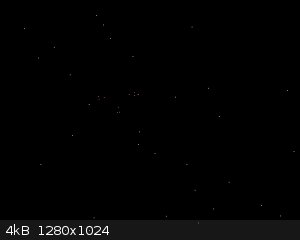
One run of the pixel detection software yields the following dots in a 1280x1024 camera image. Here the camera is appr. 7 meters (maybe 8 meters, did
not measure it) from the beacon. After pixel detection, I get the following list of pixels. Manually, by visual inspection I found out that the first
9 points are part of the beacon, the other dots are noise.
(0.75, 0.1) ===> (500, 544)
(0.85, 0.1) ===> (510, 545)
(0.8, 0.3) ===> (504, 566)
(0.1, 0.7) ===> (422, 600)
(0.1, 0.8) ===> (419, 611)
(0.3, 0.75) ===> (444, 607)
(1.3, 0.75) ===> (551, 620)
(1.5, 0.7) ===> (574, 616)
(1.5, 0.8) ===> (573, 628)
(1116, 146)
(749, 609)
(977, 246)
(380, 577)
(591, 407)
(797, 322)
(832, 212)
(589, 620)
(104, 901)
(441, 917)
(163, 776)
(594, 461)
(1254, 377)
(846, 72)
(412, 957)
(889, 647)
(567, 783)
(1197, 102)
(470, 860)
(308, 446)
(709, 101)
(819, 908)
(661, 369)
(911, 132)
(174, 322)
(401, 94)
(299, 704)
(1226, 638)
(935, 526)
(231, 822)
A dot can be one pixel or so off in x or y-direction. I only get integer values from the image processing, so I lose a little precision, but it is not
severe.
In the included image, you see the beacon and you see other dots. The coloring of the dots of the beacon is something I did just for highlighting. In
the real robot and its software, the dots are just a pair of numbers without any other attributes.
[Edited on 31-5-18 by woelen]
|
|
|
woelen
Super Administrator
Posts: 7977
Registered: 20-8-2005
Location: Netherlands
Member Is Offline
Mood: interested
|
|
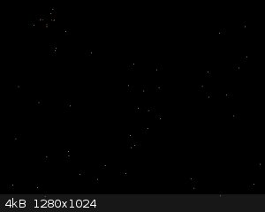
In the run for this post, the robot is much closer to the beacon. It is 3 meters or so from the beacon and it is looking a little upwards. Again, 9
dots are part of the beacon, the rest is noise. Now I have less noise.
(0.75, 0.1) ===> (537, 121)
(0.85, 0.1) ===> (573, 117)
(0.8, 0.3) ===> (560, 188)
(0.1, 0.7) ===> (330, 348)
(0.1, 0.8) ===> (335, 383)
(0.3, 0.75) ===> (402, 359)
(1.3, 0.75) ===> (747, 329)
(1.5, 0.7) ===> (815, 304)
(1.5, 0.8) ===> (819, 340)
(521, 378)
(245, 588)
(198, 482)
(776, 476)
(731, 70)
(276, 711)
(211, 104)
(433, 970)
(904, 17)
(495, 119)
(1073, 857)
(172, 262)
[Edited on 31-5-18 by woelen]

|
|
|
woelen
Super Administrator
Posts: 7977
Registered: 20-8-2005
Location: Netherlands
Member Is Offline
Mood: interested
|
|
At a distance of 15 meters (maybe even a little more), the beacon becomes quite small in the image. It makes detection more unsure, you see that the
little triangles of the beacon become quite distorted. Here follows the dot-info and below is an image.
(0.75, 0.1) ===> (223, 896)
(0.85, 0.1) ===> (228, 895)
(0.8, 0.3) ===> (226, 907)
(0.1, 0.7) ===> (193, 926)
(0.1, 0.8) ===> (196, 930)
(0.3, 0.75) ===> (205, 928)
(1.3, 0.75) ===> (250, 926)
(1.5, 0.7) ===> (260, 923)
(1.5, 0.8) ===> (261, 927)
(331, 292)
(1227, 134)
(163, 901)
(1256, 230)
(1009, 554)
(385, 180)
(255, 979)
(225, 265)
(339, 512)
(717, 489)
(651, 321)
(508, 223)
(187, 528)
(768, 600)
(608, 186)
(646, 715)
(1093, 564)
(76, 353)
(1004, 675)
(937, 114)
(1060, 863)
(218, 74)
(1183, 895)
(1064, 77)
(1154, 695)
(775, 450)
(332, 270)
(246, 957)
(634, 310)
(318, 872)
(1191, 748)
(267, 779)
(629, 368)
(977, 606)
(756, 686)
(667, 501)
(922, 159)
(441, 768)
(180, 116)
(1129, 464)
(61, 130)
(471, 157)
(713, 402)
(89, 605)
(694, 584)
(271, 790)
(620, 610)
|
|
|
woelen
Super Administrator
Posts: 7977
Registered: 20-8-2005
Location: Netherlands
Member Is Offline
Mood: interested
|
|
Finally, if no beacon is in view, or just part of it, then the software must tell that there is no beacon in view.
I think that solving this problem is quite a challenge. I still have 5 weeks though and a few spare evenings.
|
|
|
Twospoons
International Hazard
Posts: 1282
Registered: 26-7-2004
Location: Middle Earth
Member Is Offline
Mood: A trace of hope...
|
|
Are you designing the beacon? If so perhaps you could make it flash - then you could use image subtraction to make it stand out from all the static
lights in your arena, which should make the pattern recognition problem easier.
Helicopter: "helico" -> spiral, "pter" -> with wings
|
|
|
aga
Forum Drunkard
Posts: 7030
Registered: 25-3-2014
Member Is Offline
|
|
Good idea Twospoons.
Flashing in a predictable pattern would make it a little easier.
From the 'star map' images it appears that the robot will not always be horizontal, making the problem an entire dimension more difficult.
|
|
|
Twospoons
International Hazard
Posts: 1282
Registered: 26-7-2004
Location: Middle Earth
Member Is Offline
Mood: A trace of hope...
|
|
If you do go this route its important to take the two images an integer number of mains cycles apart - this removes most of the lighting flicker from
the equation.
Removing ambient light is one of the issues I had to deal with when I was doing coding and hardware design work for an optical touchscreen company
many years back.
Come to think of it, coded flashing may sufficient for the beacon without the need for pattern recognition- you would only need one LED to be visible
and the flash rate could tell you which one it is, should you want several beacons in your arena. That would certainly make the coding far easier, as
it reduces to a one dimensional problem.
Helicopter: "helico" -> spiral, "pter" -> with wings
|
|
|
woelen
Super Administrator
Posts: 7977
Registered: 20-8-2005
Location: Netherlands
Member Is Offline
Mood: interested
|
|
I also have been thinking of a blinking LED (e.g. at 20 Hz), but this introduces a lot of other difficulties. Exact image subtraction is not possible.
The robots move with speeds in the order of magnitude of 1.5 m/s (let's say, normal human walking speed) and they can rotate around their axis in 10
seconds or so. They are not fast at all, but with these low speeds, even in 50 ms, you have quite some shift and rotation of the image, so you need to
transform the image. The static noise also is not that static. Part of the noise stems from specular reflections and these can appear on a very
specific angle and disappear as fast again as they appear.
|
|
|
aga
Forum Drunkard
Posts: 7030
Registered: 25-3-2014
Member Is Offline
|
|
Perhaps a lower blink-speed, e.g. 5hz, would help, if the robot isn't whizzing about.
Exclude every image where the desired pattern is not fully present, or appears to be present in the 'dead time' when you know the pattern should not
be present.
Obviously a lot of information will be lost, but it should improve the signal/noise ratio as you'll only have to work with the images that have the
'right' data.
|
|
|
Twospoons
International Hazard
Posts: 1282
Registered: 26-7-2004
Location: Middle Earth
Member Is Offline
Mood: A trace of hope...
|
|
OK, giving away all my secrets now 
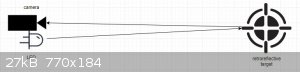
How about a passive beacon with an active camera?
The beacon is made using retroreflectors - either moulded plastic like you find on the back of a bicycle or retroreflective sheet as used on street
signs.
The camera has a light source right beside the lens, that is controlled by your rpi.
The magic of retroreflectors is that they send light back where it came from (look up 'corner cube prism' if you want to know how this works). So it
only looks bright to the camera if the camera's light is turned on. Snap two pics ms apart, one with the light on, one with it off, and the retro
target should stick out like a dog's proverbial.
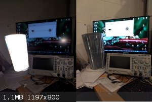
Below is a diagram of the camera/light/target setup. And a photo of a roll of retroreflective sheet that I got from my days doing optical touchscreens
- shot with and without flash. With the flash the image is completely saturated - and if I let the camera pick the exposure the background is black
and all you can see is the retroreflector.
Surprisingly you dont need that bright a light for this to work. We were using a single IR LED to light up an entire whiteboard sized touchscreen with
this technique.
Ands thats another trick: use IR and an IR pass filter over the camera lens to remove even more of the ambient mess - unless you need the camera for
something else? Though you will need to make sure the camera doesn't have a built in IR blocking filter - if it can see the LED of an IR remote then
there's no filter.
[Edited on 1-6-2018 by Twospoons]
[Edited on 2-6-2018 by Twospoons]
[Edited on 2-6-2018 by Twospoons]
Helicopter: "helico" -> spiral, "pter" -> with wings
|
|
|
woelen
Super Administrator
Posts: 7977
Registered: 20-8-2005
Location: Netherlands
Member Is Offline
Mood: interested
|
|
I'm quite limited with choice of hardware. We have to use a Raspberry PI with a standard 5 MP camera (V1.3). It is mounted on a small wheeled robot.
The robot and cameras are fixed and already exist.
The retroreflectors are very nice though. I never have thought about that at all and it certainly is on option if I have this kind of project again
and have to select hardware as well. Some traffic signs also use this kind of reflector technique. They look very bright, regardless of viewing angle.
In the meantime I solved the problem. I have written a small Java program. It is simpler than I expected and it actually is quite robust. Here follows
the code:
Attachment: Beacon.java (337B)
This file has been downloaded 667 times
Attachment: BeaconMatch.java (8kB)
This file has been downloaded 666 times
Attachment: BeaconTest.java (3kB)
This file has been downloaded 652 times
Beacon.java just holds the beacon info (9 points).
BeaconMatch.java is the pattern matcher.
BeaconTest.java is the test code, using data I posted earlier.
I added lots of comments, so it should be easy for others to understand the code. The code also is small, just a little more than 100 lines of actual
code, the total file, including comments and empty lines is less than 200 lines.
The code has to be cleaned up a little, the matcher should return some info on the image of the beacon, it now just prints it and return null, but
that kind of bookkeeping is trivial and that I will fix lateron. The main algorithm and a robust implementation now exist and that's my main goal for
now.
[Edited on 2-6-18 by woelen]
|
|
|
aga
Forum Drunkard
Posts: 7030
Registered: 25-3-2014
Member Is Offline
|
|
Brilliant work on solving the problem woelen !
Unfortunately it's way past beer-o'clock so a look at your work will have to be a tomorrow-thing.
A Pi is a huge amount of processing power, despite it's small size/low cost.
|
|
|
|


