| Pages:
1
2
3
4 |
WGTR
National Hazard

Posts: 971
Registered: 29-9-2013
Location: Online
Member Is Offline
Mood: Outline
|
|
Here's an update:
The quartz tubing arrived, and I selected the 7mm x 9mm tube for the reaction tube. I had thought of holding the catalyst in place with a smaller
piece of quartz tubing, but I think I will instead borrow an idea from Heptylene, and use some silica wick.
I checked around town today at some "Vape" shops, but it seems that no one locally carries silica wick. eBay it is, then. I can get several feet for
a few bucks including shipping. The idea is to make a loose knot at the end of the wick and fluff it out (or something) to support the catalyst
directly on the end of the wick. The rest of the wick will be kept clean (no catalytic activity wanted there) and will be threaded through the
reaction tube all the way through the hot zone to the inlet port for the ammonia/air mixture. The wick could be tucked under the tubing just a bit,
to clamp it in place.
I put together the condenser and got some deionized water running through it. I made a short video demonstrating its operation. I decided to try a
horizontal configuration instead of a vertical one.
Attachment: Condensor.MOV (2.3MB)
This file has been downloaded 774 times
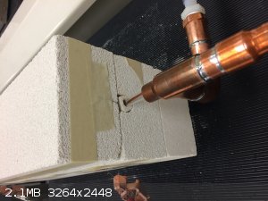
Water comes in through the 3/8" barb fitting at the right rear side and flows left through the PVC tube to the copper fittings. There is a short
copper transition from 3/4" to 1/2" tubing. At the left end of this 1/2" piece of tubing the inside diameter is necked down with a length of copper
wire, formed into a ring that fits inside the tube. This wittles down the clearance between the quartz reaction tube and the copper pipe to about
1/32". This leaves just enough clearance for water to flow through, keeping the copper piping cool. Any water that squeezes through here goes
through the 3/4" "drain" at the bottom of the copper tee fitting. It may be difficult to see from the video, but there is a bit of cotton towel
stuffed inside the open end of the copper tubing, wrapped around the quartz tube. As the water squeezes through the small 1/32" clearance in the 1/2"
coupling, it tends to travel further along the tube towards the open end, where it can possibly drip everywhere. The bit of cotton towel merely
interrupts this flow of water and strongly encourages it to go down the drain instead.
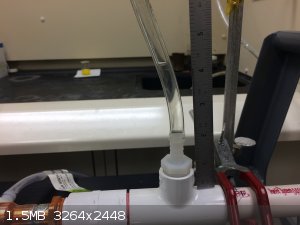
There is another plastic 3/8" barb fitting pointing up from the top of the tube. This has a short piece of tubing connected to it. This serves two
purposes:
1. It allows air to bleed completely from the top of the condenser.
2. It allows one to measure pressure at the end of the condenser, and by extension, maintain a given water flow rate through the condenser. The
pressure in the video is about 6" of water.
I have a tube furnace already assembled from a previous project that I'll use to preheat the gas flow. Some of the next things that I plan to do are:
1. Remove the reaction tube from the condenser and hook up the inlet to dry N2 and adjust the flow for a rate that is determined by the
tube diameter and some existing ammonia oxidation literature. Flow rate can be measured by water displacement vs. time.
2. Insert the tube into the furnace, such that the end of the tube protrudes slightly from the furnace. Outlet temperature can be measured with a
thermocouple, and power input for a given flow rate and preheat temperature can be determined.
3. Insert the tube fully through the furnace, and through the condenser. With the furnace active and cooling water flowing, measure the N2
temperature as it leaves the condenser, to determine if heat rejection is sufficient.
If anyone's interested, I intend to document things better as I go. I just sort-of threw everything together right now, on a brain-storming session.
Perhaps I can rebuild the condenser from scratch, showing how everything is assembled. All of it's parts come from either Lowe's or Home Depot, and
the hose clamps come from Napa.
|
|
|
j_sum1
|
Thread Split
5-8-2018 at 22:59 |
WGTR
National Hazard
Posts: 971
Registered: 29-9-2013
Location: Online
Member Is Offline
Mood: Outline
|
|
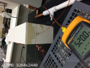
I inserted the quartz tube into the furnace and ran some brief tests today.
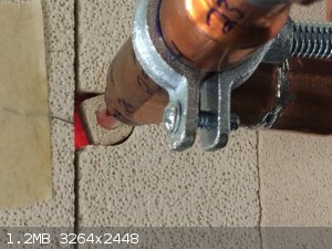
I calibrated a flow of nitrogen to be 1L/min by measuring water displacement from an inverted beaker vs. time. The 9mm quartz tube was inserted into
the furnace just enough so that the hot end barely protruded from the brick. A thermocouple junction was inserted about 2" into the tube to measure
nitrogen temperature as it exited the furnace. The nitrogen flow was connected to the inlet of the quartz tube, and the connection secured with a
fuel injection hose clamp.
After 30 minutes of running the furnace at 200-250W, a temperature of 520°C was measured by the thermocouple. This temperature seemed to be stable.
Power was removed from the furnace, and the tube allowed to cool down. Then, the tube was inserted fully through the furnace so that the condenser
could be installed. Deionized water of about 2" of water pressure (measured at the top nylon barb fitting) was used to provide cooling. Water came
in from the right rear end of the condenser, and left through the copper drain on the bottom left. The waste water was just run to a floor drain for
this test.
With a flow of 1L/min of nitrogen and the furnace operating at 200W, the temperature of the quartz tube after the condenser never deviated from
23.8°C, during the 10 minutes that measurements were taken. With this type of gas flow rate the condenser is more than adequate for the job.
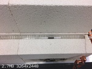
Here's a photo of the cover removed from the tube furnace:
|
|
|
Heptylene
Hazard to Others
Posts: 319
Registered: 22-10-2016
Member Is Offline
Mood: No Mood
|
|
Wow! Impressive work WGTR! I must say that furnace look just perfect for heating the reaction tube.
Do you have any concern that the quartz tube might shatter from the high temperature differential (about 500 °C difference between the furnace and
the cooling water)? I know quartz/fused silica possess very low thermal expansion coefficients and I heard that a red hot quartz piece can be plunged
in water without shattering, although I haven't tested this myself.
At any rate I am blown away by your design and the care and precision with which you report your results!
|
|
|
WGTR
National Hazard
Posts: 971
Registered: 29-9-2013
Location: Online
Member Is Offline
Mood: Outline
|
|
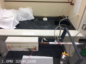
Thanks for the compliments Heptylene. I don't think there is any problem with that temperature differential on the tubing. The temperature doesn't
drop from 500°C to 25°C all at once; there is a transition that occurs once the tubing leaves the furnace. I discovered that I can measure
temperature at various points in the tubing by merely inserting the temperature probe after everything is already installed and operational, like
this:
The probe is inserted from the condenser end, to protect the wire insulation. For some reason the thermocouple insulation seems to hold up to the
output temperature of the furnace, at least for the few seconds needed to take a measurement. I noticed that there is a considerable temperature
gradient from the furnace output to the condenser input.
After thinking about it for a bit, I'd like to go back and measure the temperature at regular intervals inside the tubing, so that I can get an idea
of how quickly the furnace heats up the air, and how quickly it cools down again in the condenser. I could plot tube temperature vs. position. I'll
have to strip some more insulation off the thermocouple wire for that, so that I can push the junction further into the furnace. Do you think that
kind of data would be useful?
Here's another data point after further testing:
Flow rate, air: 3.3L/min
Input power, furnace: 250W
Temperature at furnace output: 526.5°C
Temperature at condenser output: 31.8°C
Condenser water temperature, input: 25.7°C
Water pressure: 4"
I think that I have some quartz wool in another lab, so I'll borrow a page from your book, and try soaking some of it in my hexachloroplatinic acid.
Some quick back-of-the-envelope calculations seem to show that a 3-4% ammonia solution should give a 3% concentration in air if air is bubbled through
it at room temperature. I should get some results out of that, I would think.
|
|
|
Heptylene
Hazard to Others
Posts: 319
Registered: 22-10-2016
Member Is Offline
Mood: No Mood
|
|
If measuring the temperature of the gradient is not too much of a hassle I would be interested in the results. I will probably use a similar heating
design for my reaction tube (wrapping nichrome wire coil/sleeve around the silica tube with some rock wool insulation) but I don't know how long the
heating sleeve should be.
|
|
|
WGTR
National Hazard
Posts: 971
Registered: 29-9-2013
Location: Online
Member Is Offline
Mood: Outline
|
|
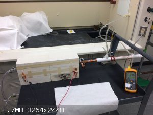
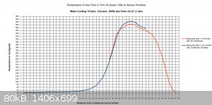
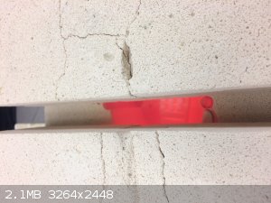
I added graduated marks to the side of the condenser and furnace for reference, and photographed the setup with a tape measure for clarity.
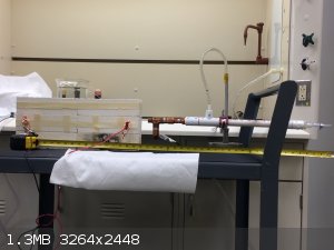
My thermocouple could only reach three feet into the tube, and the tube is four feet long. This means that I was able to reach only halfway into the
furnace with the thermocouple junction. I could go back later and gather some more data, but I'll have to remove the condenser and slide the quartz
tube back through the furnace a foot or so to be able to measure temperatures in the first half of the furnace. Anyway, you can still see the
temperature at the halfway point in the furnace, and that it is still rising until about 2/3 of the way through the furnace, then it starts to drop.
With 150W to furnace:
With 250W to furnace:
I figure that with 200W input, the temperature would max out around 500C.
Right at the 26 inch mark the temperature drops noticeably. This is because there is a cloth ring that is stuffed around the reaction tube at this
location. Its purpose is to divert water into the drain that is flowing along the reaction tube, and it remains wet constantly. The temperature is
going to vary a bit within the tube, and the gas flow may or may not be a different temperature than the walls of the tubing. The thermocouple
junction is generally touching the tubing, not directly sampling the air temperature. This also explains why the tube seems to be getting hotter as
it exists the bottom end of the condenser; the gas flow is about 40C as it exits the condenser, and there is no water flowing on the tubing right at
that point to cool down the walls of the tubing. The temperature drops off near the end of the furnace. I think this can be attributed to air
leakage from the furnace.
I set the air flow on this test to 4L/min, as this seems to approximate the conditions recorded in industry, considering the size of the tubing. It's
a starting point anyway.
If a 10% ammonia gas feed is utilized, then a 300C preheat will probably be all that is needed. If ammonia feeds drop to 1-3%, then it may be
necessary to raise the preheat temperature to 500-600C.
[Edited on 8-11-2018 by WGTR]
|
|
|
Heptylene
Hazard to Others
Posts: 319
Registered: 22-10-2016
Member Is Offline
Mood: No Mood
|
|
Thank you for the measurements, I might get away with using a 10-20 cm furnace then, although my tube is 18 mm outside diameter so extrapolating like
is probably not quite correct.
|
|
|
WGTR
National Hazard
Posts: 971
Registered: 29-9-2013
Location: Online
Member Is Offline
Mood: Outline
|
|
OK, I'm going to go back and make another set of measurements with a slower flow rate. In the references uploaded in this post for some reason I had understood that the flow rates mentioned there were for ammonia only, not the total ammonia/air mixture. Not sure why
I thought that.
I was re-reading the references again as a sanity check, because I'm getting ready to order a flow meter. It's time consuming to calculate flow rate
iteratively by measuring air displacement over water. If it's sized correctly it will be more accurate, as these meters are most accurate the closer
you are to their maximum capacity. Anyway, the measurements that I took at 4 lpm were for a flow rate that is around 3 times too much under the most
optimistic conditions.
A 7mm ID tube (9mm OD) should correspond to an internal area of 0.385 cm2. For a flow rate of 0.636 lpm/cm2, this corresponds
to a total flow rate of 0.385*0.636 = 0.245 lpm.
For the fastest flow rate of 3.51 lpm/cm2, this corresponds to a total flow rate of 0.385*3.51 = 1.35 lpm.
Realistically, I think that I'll keep the flow rate around 0.5 to 1.0 lpm. The condenser seems to handle a 1 lpm flow rate easily, and the air
exiting the condenser under that condition was practically room temperature.
I'm considering bubbling air though an ammonia solution in water to formulate the correct gas feed. If I'm understanding this correctly, a roughly
2.5-3.0% solution of ammonia in water will give a partial pressure of ammonia that is equal to that of water at 20C. The idea is that as air is
bubbled through the ammonia solution, the ammonia concentration in the solution will hopefully remain the same. This would provide a consistent gas
composition over several hours if the solution temperature can be maintained.
I pulled some data from the Wikipedia pages (not exactly an authoritative source, I know) to create a chart. I looked at the curve for ammonia, and
extrapolated the 2.5% data point.

The idea is that air would be dried with a desiccant and measured with a flow meter, then bubbled through the ammonia solution. If desired, the
ammonia/air mixture could be dried with calcium oxide before sending it to the furnace.
Assuming 24.5 liters of gas per mole at 25C and 1 atm, that corresponds to 0.0408 moles per liter. With a 2.25% ammonia concentration in air, this
gives 0.000918 moles per liter of gas feed. If the yield is 100%, this gives 3.47g of nitric acid per hour at 1 lpm gas flow. This also would
consume 0.980g of ammonia during the same time. Feel free to check my math.
[Edited on 8-11-2018 by WGTR]
|
|
|
WGTR
National Hazard
Posts: 971
Registered: 29-9-2013
Location: Online
Member Is Offline
Mood: Outline
|
|
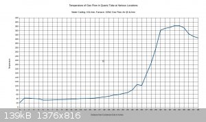
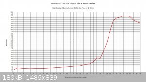
I managed to get a full temperature profile of the furnace and the condenser together, but not at the exact same time. The first set of readings was
taken of the furnace itself without the condenser installed, after the furnace operated for 1.5 hours. It was necessary to remove the condenser for
these measurements, as the temperature probe was not long enough to fit all the way through the furnace with the condenser installed. The next set of
measurements was taken after 2.5 hours, after re-installing the condenser. Part of the furnace was re-profiled, in addition to the full length of the
condenser.
These measurements were rather difficult and time consuming to do correctly, but as can be seen, the temperatures along the two curves still do not
match up exactly. This is because even after 1.5 hours the furnace continued to heat up during the following hour.
From looking at all three charts, I think it is apparent where the hottest zone is located in the furnace, and also that the condenser parameters are
adequate. After completing this one full temperature profile I don't think it is necessary to record other ones, even when other parameters such as
air flow or furnace wattage change. It should be sufficient to measure the temperature at one location in the middle of the hot zone.
Unfortunately, I think it is necessary to add a PID controller to the furnace. I already have one so this is no problem for me. It is an added
expense for others, though. At the same time it simplifies control of the furnace. I am currently providing power via an adjustable DC power supply,
and most people do not have one of these high power units. In contrast a PID controller with an SSR can run directly from the AC outlet.
I currently have a flow meter on order for the gas supply. I am getting one of these for development purposes, but I don't think it is necessary for
everyone to get one of these. It is possible to measure air flow by measuring how fast the air can push water out of an inverted beaker. If it
pushes out 1 liter in one minute, then that is 1 lpm air flow.
One additional point is that I managed to center the thermocouple junction within the tube, so it's measuring actual air temperature, and there isn't
that characteristic "hump" right there at the end of the condenser that was seen in previous charts.
That is all for now, probably until next weekend.
[Edited on 8-13-2018 by WGTR]
|
|
|
WGTR
National Hazard
Posts: 971
Registered: 29-9-2013
Location: Online
Member Is Offline
Mood: Outline
|
|
Quote: Originally posted by Heptylene  | Thank you for the measurements, I might get away with using a 10-20 cm furnace then, although my tube is 18 mm outside diameter so extrapolating like
is probably not quite correct.
|
Keep in mind that the internal area of the tube increases approximately twice as fast as its external surface area. Heat transfer becomes more
difficult for a given length of tubing the larger its diameter becomes. The inverse is also true, internal area decreases twice as fast as the
circumference, when going to smaller tubing. I know that 48" tubing carries a hefty shipping charge because of the length. That's unfortunate. Off
the top of my head I think I paid $30 or $40 for shipping, so I bought $50 worth of quartz just to make it worthwhile. If you want to stick with 18"
long tubing, I'd suggest going to a smaller diameter, maybe 4 or 5mm ID.
If you look over my chart with the full temperature profile, you can get an idea how fast the temperature comes up, and how quickly heat is rejected
to the condenser. That is for 7mm ID tubing (9mm OD). Hopefully this will get you started.
Referring to the graduations marked on the condenser (in the picture), the quartz tube is submerged fully in water from 3" to the 23" position. From
23" to the 26" position, water trickles along the underside of the tubing until it gets diverted to the copper drain by a piece of paper towel wrapped
around the tube.
[Edited on 8-13-2018 by WGTR]
|
|
|
WGTR
National Hazard
Posts: 971
Registered: 29-9-2013
Location: Online
Member Is Offline
Mood: Outline
|
|
It may be possible to use borosilicate tubing instead of quartz, if that is a more available option to some people. Quartz will of course, be the
best option for thermal shock resistance and temperature rating, but I don't think that the temperature is yet too high to use boro if it's being
preheated to around 400-500°C. That is for a straight piece of tubing, nothing fancy. I wouldn't go significantly higher in temperature though,
hence the use of a PID controller.
Whenever I've seen someone use preheating for an Ostwald process, the heat always seems to be concentrated in a small area of the tube. Naturally, in
that case it will be necessary to use quartz since the localized temperatures need to be high to get enough preheating. At the same time, if the
heating is spread over a long length of the tubing, then this may not be an issue. With an 18" long furnace, I noticed that the preheating was
gradual enough that even when operating around 500°C, the interior of the furnace wasn't even glowing. In fact, it was necessary to turn off the
lights and get acclimated to the dark to even see a faint, dark red glow.
I happen to have a piece of 9mm borosilicate laying around, the same size as my quartz tubing. It's not a full length piece, but at 3.5' it's long
enough to bring up to temperature and check for suitability.
|
|
|
Chemetix
Hazard to Others
Posts: 375
Registered: 23-9-2016
Location: Oztrayleeyah
Member Is Offline
Mood: Wavering between lucidity and madness
|
|
Just a heads up with boro, it goes soggy very quickly as an oxidiser chamber. The catalyst will get to 700C easily. Boro starts getting a bit mushy at
this stage. Quartz, aluminosilicate, or ceramic are going to be the materials of choice.
I'm appreciating your ever precise building style. I am anticipating your first couple of runs.
[Edited on 15-8-2018 by Chemetix]
|
|
|
WGTR
National Hazard
Posts: 971
Registered: 29-9-2013
Location: Online
Member Is Offline
Mood: Outline
|
|
| Quote: Originally posted by Chemetix | Just a heads up with boro, it goes soggy very quickly as an oxidiser chamber. The catalyst will get to 700C easily. Boro starts getting a bit mushy at
this stage. Quartz, aluminosilicate, or ceramic are going to be the materials of choice.
I'm appreciating your ever precise building style. I am anticipating your first couple of runs.
[Edited on 15-8-2018 by Chemetix] |
Thanks for the compliments there, you and VSEPR_VOID. It’s much easier for me to pursue something like this when I know that others are interested
in it as well.
I think that your words of caution are well-placed about the use of borosilicate tubing for this type of application, and they are probably prophetic.
I don’t plan on trying out the boro right away since I have other points of investigation that are more pressing, and already have a good tube made
of quartz to play with. However, I have a number of different ideas floating around back there in my head (too many to try and list), and it seems
slightly possible with the right combination of variables that boro might actually work. If it did work it would be marginal for sure, but it would
be cool, because I can buy 4’ borosilicate tubing on the way into work every morning if I wanted to, with no shipping charges. The same store
doesn’t sell quartz.
Here’s my thought process on this: I’m not thinking of using a 10% ammonia feed. Referring to a chart from this reference https://www.sciencemadness.org/whisper/files.php?pid=525953&...
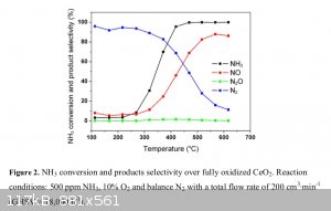
selectivity to nitric oxide over nitrogen gas begins to be noticeable around 400C with a ceria catalyst. At 500C it’s at 70-80% already. This is
with only a 0.05% (500ppm) ammonia feed, so in this case I don’t think the temperature rise is very measurable during that oxidation. Using such a
diluted feed would be impractical in our case, since with a 3% feed I think that yields would be around 3g per hour of acid if everything goes more or
less correctly. It would be interesting to see how high I can get the ammonia feed % without getting much temperature rise from the oxidation.
Diluted ammonia feeds also give diluted nitric oxide products. These oxidize much more slowly to nitrogen dioxide as the dilution increases. This
might seem to be a bug, but really I think it’s a feature. With a 7mm tube ID and, let’s say, a 600ml/min flow rate, that should translate to a
flow rate of 10” per second through the tube. I’m already flowing more air than that through the condenser, and the condenser is still overkill.
It cools down the air almost immediately. Anyway, the dilute nitric oxide would simply not have enough time to oxidize to a noticeable degree in the
condenser due to the matter of seconds spent in the tube.
The output gasses could then be bubbled through a very cold (below freezing) nitrate salt solution in order to remove most moisture from the gasses.
Some nitric oxide may be lost as nitrate in this solution, but the idea is that the losses would be very minimal. Silica gel can be used to both
remove moisture, and also catalyze the oxidation of nitric oxide to nitrogen dioxide. The former reaction is much faster than the latter, however,
and the overall effect is a matter of residence time. Also, moist silica gel does not catalyze nitric oxide oxidation. The first stage of silca gel
would be located in a short tube to remove any residual moisture not captured by the chilled salt solution. Gasses would pass very quickly through
this. Following a void space for oxidation, the following stage of silica gel would serve to catalyze the oxidation of the dry nitric oxide, and also
to capture the resulting nitrogen dioxide. Gasses would pass very slowly through this catalyst bed. Practically I plan to use indicating silica gel
for moisture adsorption, and non-indicating for nitrogen dioxide adsorption (it is it’s own indicator).
To measure yield, before and after weights of the second silica gel stage will be taken, and yields will be based on the weight of dry nitrogen
dioxide.
|
|
|
WGTR
National Hazard
Posts: 971
Registered: 29-9-2013
Location: Online
Member Is Offline
Mood: Outline
|
|
I was hoping to find an ammonia concentration in solution that would allow me to maintain a constant concentration as the solution was evaporated by
the air that I would be bubbling through it. Due to excessive brain flatulence (how else can I describe it?) I completely misinterpreted my carefully
plotted ammonia chart, and thought that ammonia and water would form an azeotrope at low concentration. Technically it may form one at 0.001% or
something, but the main point is that I need way more ammonia than this, on the order of a few percent concentration in air.
Since I can’t rely on the solution remaining at the same concentration during the course of the experiment, I had to decide just how much variation
in concentration that I could tolerate during the course of the experiment. Given a certain experiment duration, this in turn would determine how
much ammonia solution that I need of a given starting concentration.
This problem requires a bit of calculus, something that I haven’t done in quite a while. I enjoy math, but find it time-consuming, and it makes my
head hurt. Also, many times math does not enjoy my company so much, and will fight me by giving stupid answers and mistakes. Hopefully this time
will be better. Check my math please! Anyway, although my brain cells were crying, I dusted them off and forced them to wake up.
I’m planning to start with an air flow of 0.6L/min, bubbling through the ammonia solution. It may change a bit one way or the other, but this seems
like a good starting point. I also figured to start the experiment with a 4% ammonia concentration in air, and could tolerate a drop down to 3%
during the course of the experiment.
Using data pulled from this chart the corresponding values of ammonia concentration in air were plugged in:
For a 4.5% solution (by mass) of ammonia in water:
\[\frac{4.5\%\, NH_3\, sol'n\, mass}{1} * \frac{4.0\%\, NH_3\, vol\, air}{4.5\%\, NH_3\, sol'n\, mass} *\frac{1}{100\% \, NH_3\, vol\,
air}*\frac{1mol}{24.5L} *\frac{17.034g\, NH_3}{1mol}* \frac{0.600L}{1min} *\frac{17.034g}{17.034g + 18.06g}*\frac{100\%}{50\%} = \frac{0.0162g\,
NH_3}{min}\]
For a 3.5% solution (by mass) of ammonia in water:
\[\frac{3.5\%\, NH_3\, sol'n\, mass}{1} * \frac{3.0\%\, NH_3\, vol\, air}{3.5\%\, NH_3\, sol'n\, mass} *\frac{1}{100\% \, NH_3\, vol\,
air}*\frac{1mol}{24.5L} *\frac{17.034g\, NH_3}{1mol}* \frac{0.600L}{1min} *\frac{17.034g}{17.034g + 18.06g}*\frac{100\%}{50\%} = \frac{0.0122g\,
NH_3}{min}\]
So at the start of the experiment, 0.0162g of ammonia is stripped from the solution every minute. At the end of the experiment, the ammonia removal
rate has dropped to 0.0122g per minute, since the solution concentration has decreased. These values are assuming that I can maintain a constant
solution temperature of 20°C. Estimating the slope to a straight line equation:
\[\frac{-\left ( 0.0162 -0.0122 \right )x}{t}+0.0162 = \frac{-0.00400x}{t}+0.0162 \,,\: \: t = total\, time\, in\, minutes\]
Let’s say that we want the experiment to run for 240 minutes, to give time for experimental conditions to reach steady state. We want to be able to
get good yield data, and want to minimize the amount of time that the experiment is either ramping up or down. We want to know how much ammonia will
be used during the course of the experiment, so we can calculate how much 4.5% solution we need:
\[\frac{-0.00400x}{240}+0.0162 = -0.000016667x+0.0162\]
\[\int_{0}^{240}\left ( -0.000016667x+0.0162\right )dx\]
\[\left | \left [ -0.000008333x^2+0.0162x + C\right ]_{0}^{240}\right |\]
\[\left | -0.000008333\left ( 0\right )^2+0.0162\left ( 0 \right ) + C + 0.000008333\left ( 240 \right )^2-0.0162\left ( 240 \right ) - C \right |\]
\[\left | 0.480-3.89 \right |= 3.41g\,NH_3\]
For a sanity check, we take the starting value for the concentration and plug in the rate for the full 240 minutes: \[0.0162 * 240 = 3.89g\,NH_3\]
Good, the absolute value is greater than our answer. Now plugging in the minimum rate for 240 minutes: \[0.0122 * 240 = 2.93g\,NH_3\]
This also looks good, as the absolute value is less than our answer, and the final answer is reasonably between these two limits. From there we want
to determine how much ammonia solution that we need.
\[\frac{3.41g\,NH_3}{1} * \frac{100\%\, NH_3\,sol'n}{\left ( 4.5\%-3.5\%\right )\,NH_3}=341g\,NH_3\, sol'n\]
Checking out this number:
\[\left ( \frac{341g}{1} * \frac{4.5\%}{100\%}\right )- \left ( \frac{341g}{1} * \frac{3.5\%}{100\%}\right ) = 3.41g\]
This is a useful online LaTex equation editor:
https://www.codecogs.com/latex/eqneditor.php
[Edited on 8-20-2018 by WGTR]
|
|
|
WGTR
National Hazard
Posts: 971
Registered: 29-9-2013
Location: Online
Member Is Offline
Mood: Outline
|
|
Platinum Loaded Ceramic Beads
I made some ceramic beads and infused them with platinum.
20ml of deionized water was warmed gently in a 25ml glass beaker on a hot plate, and stirred vigorously using a magnetic stir bar. A glass cover was
placed over the beaker to keep evaporation to a minimum. 2.00g of bentonite clay was carefully added to the beaker under heavy stirring.
Eventually, all of the clumps dissolved into a brown suspension, and the solution was allowed to stir for an additional 30 minutes. Then, 18.00g of
alumina was stirred in as well, and 30 more minutes were allowed for the bentonite and alumina to thoroughly mix together, and for the bentonite to
fully hydrate.
The resulting suspension had low viscosity, and much extra water. The clay was de-watered by carefully pouring the contents of the beaker onto
absorbent paper towels. After standing for several minutes excess water floated to the top of the clay and ran off, or was soaked into the towels. A
metal spatula was then used to scrape the clay together from the towels.
With much care, small pieces of the clay were rolled by hand into round beads and pills. The clay seemed plastic enough to form, so long as the
moisture remained sufficient. A bit too much moisture caused the clay to become very gooey and soft, and too little caused the clay to become stiff
and non-cohesive. The right amount gave a firm clay that could still be gently shaped.
The resulting clay bodies seemed porous enough to dry rapidly, and they seemed dry under warm air after only an hour. Still, they were allowed to dry
in ambient room air overnight before firing. In their green state the clay seemed fairly strong and could be easily handled, but no attempt was made
to try to test the strength by crushing samples.
The beads were placed in a small kiln (linked in signature) and ramped slowly up to 1200°C over a period of about 3 hours. One half hour was spent
at 100°C to make sure that everything was dry, then the kiln was ramped to 1200°C. The kiln spent 20 minutes soaking between 1200°C and 1210°C.
The kiln was allowed to cool down naturally to 1000°C, and then the lid was opened partially. Cool-down was rapid at this point.
|
|
|
WGTR
National Hazard
Posts: 971
Registered: 29-9-2013
Location: Online
Member Is Offline
Mood: Outline
|
|
The sintered clay samples were quite strong after firing. One piece was dropped from a height of 1 foot, and it just bounced on the table top. They
all gave a characteristic sharp “tap” when dropped into a glass dish.
Previously prepared 5mM hexachloroplatinic acid in ethanol was used to prepare the catalyst. I prepared this solution some years ago, and if I
labeled it correctly, there is only 10mg of platinum in this 100ml of ethanol solution. If I labeled it incorrectly, then it’s about 100mg of
platinum in 100ml of ethanol. I found the reference that I used to prepare the solution, and it specified 5mM. Anyway, it is less than $5 of
platinum in the entire container.
One ceramic bead was introduced carefully to a single drop of water. Once touched, the water was immediately adsorbed. The beads appeared to be
finely porous, though mechanically strong. Generally, the ceramic beads were gripped with stainless steel tweezers, and heated with a heat gun to
make sure they were dry. They were cooled down briefly in cool air and then dipped into the ethanol solution. Vigorous bubbling was evident right
when the beads were submerged into the ethanol. The bubbles appeared to be trapped air, as they ascended completely to the top of the ethanol without
being reabsorbed.
In the following video, you can see how the bead that is wet with ethanol solution is dried with a heat gun. Upon further heating, the chloroplatinic
acid decomposes and platinum appears on the bead.
Attachment: Pt_loaded_ceramic_support.mpg (5.9MB)
This file has been downloaded 676 times
Old video replaced with new one
[Edited on 8-25-2018 by WGTR]
|
|
|
WGTR
National Hazard
Posts: 971
Registered: 29-9-2013
Location: Online
Member Is Offline
Mood: Outline
|
|
Once the ceramic bead was heated to the decomposition point of the platinum salt, the bead was cooled down and reintroduced back into the ethanol
solution, and this cycle was completed four times in totality. The following video shows the fourth cycle in progress. Note how dark the bead is by
this point. Practically none of the ethanol solution has been used, and it’s probably less than a few cents of platinum for each bead.
Attachment: Pt_loaded_ceramic_support_4th_cycle.mpg (4.9MB)
This file has been downloaded 678 times
Can you see the difference between coated and uncoated samples?

If you look closely you can see that there are some small pinholes that are not covered well with platinum. Looking under high mag with an optical
microscope, it appears that those small areas are relatively non-porous. The ethanol solution was simply not able to soak into those areas very well.
Video file updated
[Edited on 8-25-2018 by WGTR]
|
|
|
WGTR
National Hazard
Posts: 971
Registered: 29-9-2013
Location: Online
Member Is Offline
Mood: Outline
|
|
The last video for tonight briefly shows how the beads bubble when initially placed under the ethanol solution. This bead was a bit warm before being
submerged.
Attachment: Pt_loading.mpg (5.8MB)
This file has been downloaded 690 times
Video updated
[Edited on 8-25-2018 by WGTR]
|
|
|
WGTR
National Hazard
Posts: 971
Registered: 29-9-2013
Location: Online
Member Is Offline
Mood: Outline
|
|
I just updated the videos in the last few posts. I wasn't too happy with the previous ones. From now on, I plan to use a normal DVD recorder instead
of the phone. Too many complications trying to get good video off the phone to a Linux machine.
|
|
|
WGTR
National Hazard
Posts: 971
Registered: 29-9-2013
Location: Online
Member Is Offline
Mood: Outline
|
|
I decided to measure the platinum loading % on a ceramic bead, just so i could present a measurable result that is hopefully duplicable by others. I
picked out a fresh ceramic ball from my recently fired batch, and weighed it on a microbalance. This was a bit tricky, as I was unsure whether or not
the ceramic was picking up room moisture, and if so, how quickly. One additional complication is that the ceramic bead is heated as part of the
loading procedure, and heat will cause the microbalance to drift slightly during the measurement. Finally I decided on a procedure that involved
setting the bead out in ambient conditions for a fixed amount of time between each weighing cycle, and to make several mass measurements and zero out
the balance each time until a stable reading was obtained. The following results were obtained for one bead:
-bare ceramic bead: 0.310291g
-after 1st coat: 0.310301g
-after 2nd coat: 0.310392g
-after 3rd coat: 0.310451g
-after 4th coat: 0.310520g
I should mention, that these measurements were obtained after each successive coating, after the bead was heated enough to decompose the Pt salt.
According to these measurements there are only 229 micrograms of platinum loaded onto the bead. That equates to roughly $0.006 of platinum on the
single bead at a loading of 0.074%.
|
|
|
Heptylene
Hazard to Others
Posts: 319
Registered: 22-10-2016
Member Is Offline
Mood: No Mood
|
|
Incredible! That's a nice catalyst support, I'm guessing the beads fit in the reaction tube right? They seem quite porous from their bubbling in
water.
How did you get access to a microbalance? I can't imagine those are common outside very specialized research labs. The best I've seen was at my uni
had 10 micrograms resolution.
The coating with platinum by thermal decomposition seems to be a better method than that by reduction with hydrazine which I've been using. The
problem with hydrazine reduction is that most of the platinum just forms a suspension in the solution (which I recycle of course) and doesn't stick to
the substrate. I'll try thermal decomposition if I need to make more catalyst.
Btw I haven't been able to reply to your U2U, I'm having problems sending messages. I hope this will be fixed soon.
|
|
|
WGTR
National Hazard
Posts: 971
Registered: 29-9-2013
Location: Online
Member Is Offline
Mood: Outline
|
|
| Quote: Originally posted by Heptylene | Incredible! That's a nice catalyst support, I'm guessing the beads fit in the reaction tube right? They seem quite porous from their bubbling in
water.
How did you get access to a microbalance? I can't imagine those are common outside very specialized research labs. The best I've seen was at my uni
had 10 micrograms resolution.
The coating with platinum by thermal decomposition seems to be a better method than that by reduction with hydrazine which I've been using. The
problem with hydrazine reduction is that most of the platinum just forms a suspension in the solution (which I recycle of course) and doesn't stick to
the substrate. I'll try thermal decomposition if I need to make more catalyst.
Btw I haven't been able to reply to your U2U, I'm having problems sending messages. I hope this will be fixed soon.
|
Yes, the beads just roll right into the tube...and like bad chili, come rolling right out the other end. But I also have some pill-shaped pieces of
ceramic that are heavy enough to hold the catalyst in place. At least this arrangement seems to work at room temperature, with 0.6 liters per minute
air flow. I'm hoping that will be sufficient.
I do work in a lab, one that I won't name publicly to respect both its and my respective privacies. But yes, I do have access to a microbalance, as
well as an XRAY system, SEM, high res optical microscopes, etc. It's enough to get by. But this is nothing compared to a well-funded public
university, who has government grants full of crazy money. A local one has equipment that is so far advanced and expensive that I could only dream of
it.
The solution in the video isn't water actually, but ethanol. Hexachloroplatinic acid is soluble enough in it to dissolve completely at these minute
concentrations. I originally made the solution so that I could dip coat a platinum coating onto a glass slide, back when I was making counter
electrodes for dye-sensitized solar cells (see link in signature). The original journal article that I was following actually specified 100%
isopropanol, but the ethanol was more readily available to me at the time. After thinking about it overnight, I really do need to verify the platinum
concentration in the solution that I was using. There's little usefulness to the amateur community in taking such care to weigh samples if we don't
know how much platinum was in the solution to begin with, right? Like you say, not everybody has a microbalance. Presumably if we know the starting
concentration of the platinum solution, and exactly how the ceramic beads were made (mentioned in a previous post), then it should be possible for
anyone to get a similar Pt loading that I did. Being able to weigh the results would just be an added bonus. While I'm thinking about it, the
bentonite and aluminum oxide are all pottery grade, and came from a local pottery store.
Even if I was confident that my bottle label was correct, over the years some of the platinum has precipitated out as a very fine powder in the
ethanol, presumably reduced very slowly at room temperature by the ethanol. This precipitate is quite dense, and sits contently at the bottom of the
container. I suppose that I could take 1 ml of the Pt solution and evaporate it in a weighing bottle, reduce it to metallic Pt, dry it, and see what
kind of results that I get. If I have to, I can keep evaporating several ml's of solution in the same bottle, until I get enough to weigh reliably.
I'm starting to get a bit impatient (probably like everyone else), and am thinking of running some ammonia vapor through the reactor today, just to do
a qualitative test to answer some basic questions, like "Is the catalyst active enough?", "Is it too active?", "Is the catalyst geometry sufficient?",
and most importantly, "how does pH paper respond to the gases coming from the condenser?". I'm not planning on taking any real measurements at this
point.
I was honestly not expecting the platinum to be that visible on the ceramic. That was a bit of a surprise. In regards to the bubbling observed when
inserting the ceramic beads into the ethanol, I'm a bit undecided on what the gas is. I initially decided that it was trapped air, and it may be. As
I mentioned before, however, the beads were still warm from being heated by the heat gun. When the beads are at room temperature they still bubble,
but very slowly and not as much, I think. While it's possible that the faster bubbling when the beads are warm is due to a change in surface tension
of the alcohol at the localized higher temperatures, it's also possible that the gases contain carbon dioxide from the decomposition of ethanol. When
the beads are very warm, it's conceivable that platinum metal internal to the bead is quite hot, and catalyzes the decomposition of ethanol with the
air that's trapped internally. Some water or acetic acid or something would be produced as by-products. If you look carefully at the video, you can
see that something is floating off of the bead other than just gas, maybe some product is dissolving into the alcohol. It's not something I intend to
investigate carefully, anyway.
[Edited on 8-26-2018 by WGTR]
|
|
|
WGTR
National Hazard
Posts: 971
Registered: 29-9-2013
Location: Online
Member Is Offline
Mood: Outline
|
|
I checked the mass of platinum per ml for my Pt/ethanol solution, and came up with some reasonable results. I tared the measuring vial at 2.230,588g.
0.5ml of the solution was evaporated in the vial, and then the remaining Pt salt was decomposed with heat to leave a black residue in the vial.
After cooling, the total mass of 2.231,227g was obtained.
\[\frac{1\, mol\, Pt}{195.08g\, Pt} *\frac{\left ( 2.231227g-2.230588g\right )}{1}*\frac{1}{0.5\, ml}=\frac{0.000,006,551\, mol}{1\, ml}\]
or, 0.000,655 mol/100ml.
This is neither the expected 0.005 mol/100 ml or 0.000,5 mol/100 ml, but the results are fairly close to the latter. Some measurement error is likely
in all the different steps that I performed from synthesis to final mass measurement. Over the years, it's possible that some alcohol evaporated from
the bottle. Anyway I think that the original label reads correctly, "5 milli-molarity H2PtCl6 in 100ml ethyl alcohol". The
measurements are giving roughly 1mg Pt per ml ethanol.
In reality, any rough concentration of platinum in alcohol similar to 0.5-1mg per ml should give you results similar to what I got. You can buy 1
grain of platinum on eBay for less than $7 including shipping. This is about 67mg of Pt, enough to make between 50 and 100ml of solution. I used ethanol, but
isopropanol should work also as the solvent.
,
Edit: You know, I just checked the molar mass of PtCl2, and it is about 266 g/mol. Platinum is about 195 g/mol. The difference in molar
weights is about the same as the error that I'm seeing in the measurements. So maybe my measurements are only a few % off, and I'm just not heating
the platinum salt hot enough to achieve pure platinum, but rather platinum (II) chloride. The next task is to check the catalyst for activity.
[Edited on 8-27-2018 by WGTR]
|
|
|
WGTR
National Hazard
Posts: 971
Registered: 29-9-2013
Location: Online
Member Is Offline
Mood: Outline
|
|
Tonight, I joined the Ostwald club...
I’ll have wait for the weekend to say much due to time constraints. This was just a qualitative go/no-go test. However, I bubbled 150ml/min of air
through a 2-3% solution of ammonia using one of those fish tank air stones, with 300W input to the furnace. Three catalyst beads were used, placed in
between two bare ceramic pills to hold them in place. I started with 600ml/min but found that it was way too much air flow; ammonia was getting
through and forming a cloud of ammonium nitrate after the condenser. It’s not a surprise, really. The catalyst beads block most of the tube, and I
was calculating air flow based on the old figures related to platinum mesh.
I had to bump up the furnace temperature a bit. Unfortunately Chemetix is right, borosilicate isn’t going to work in this application. In room
light the furnace was glowing dull orange; in the dark it was more of a bright orange. I’ll have to measure the exact temperature when I have the
chance, but it’s probably around 800°C.
I put a bit of water in a 2l vacuum flask and bubbled the brown gas through that. There was still some faint yellow coloration in the flask, but a
lot of it seemed to be absorbing into the water. The clear tubing leading to the flask was noticeably colored light brown/yellow.
After a couple of hours I ended up with about 50ml of acid, but I need to titrate it. The pH measured at 1, which doesn’t mean a whole lot. I’ll
dilute a bit of it out 10:1 and recheck the pH as a quick test. I’d be surprised if I had more than 0.5g of acid in there, with all of the
different flow rates, temperatures, and everything else that I was trying. I originally calculated my anticipated yield based on a 600ml/min flow
rate and a 3-4% ammonia concentration in air. With a slower flow rate, inefficient gas absorption, and some acid left in the condenser, well, I’m
not expecting too much.
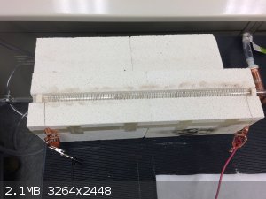
I looked at the catalyst beads after the experiment, and they look just like the day they were born, no apparent change. The air flow didn't push
them down the tube; they stayed put. There was no staining or damage on the quartz tubing that I could see. The clear PVC tubing seemed to hold up
to the cool exit gases and acid vapor, but it remains to be seen how long it will last.
|
|
|
WGTR
National Hazard
Posts: 971
Registered: 29-9-2013
Location: Online
Member Is Offline
Mood: Outline
|
|
For now, some pictures...
Furnace glowing:
Catalyst beads after furnace cool-down:
Jar full of NO2:

[Edited on 8-30-2018 by WGTR]
|
|
|
| Pages:
1
2
3
4 |
|


