| Pages:
1
2
3
4 |
WGTR
National Hazard

Posts: 971
Registered: 29-9-2013
Location: Online
Member Is Offline
Mood: Outline
|
|
I've let the reactor run for a few hours, and it looks like right now I'm getting around 0.5-1 gram of acid per hour. Those numbers resulted from
some quick tests. If those numbers hold during later tests, then conversion % of ammonia to nitric oxide is not bad. I really need to let it run a
full day to get a better idea, as a certain amount of acid gets held up in the condenser and tubing. Once the concentration of acid gets high in
those areas, the acid starts breaking down back to nitrogen dioxide, and that gas gets pushed closer towards my absorption system. Right now I'm
getting about 0.5 grams per hour absorbed into a 250ml graduated cylinder. I'm probably losing quite a bit of nitric oxide from there, as my
absorption system isn't even close to being large enough.
It's not a phenomenal amount of acid production by any means, but I wonder what people here really hope for. A liter of acid per month? Per week?
Or...per day? For me, I have a large 4 liter beaker that had stubborn carbonate stains all over it. I cleaned it with some diluted acid from an
earlier run and the whole beaker shined right up. But I don't have any real needs for large amounts of nitric.
Right now I'm using about 300W in the furnace, which is too much $. I'm considering rebuilding the furnace to be a bit tighter and smaller, and will
hopefully get the power down to about 1/3 what it is now.
|
|
|
WGTR
National Hazard
Posts: 971
Registered: 29-9-2013
Location: Online
Member Is Offline
Mood: Outline
|
|
PVC Tubing and 800°C Ceramic Beads have Compatibility Issues
That is an important lesson that I learned tonight. This may seem obvious, of course, but sometimes the tired or the stupid need to be reminded of
such things.
Tired and in a hurry, I wanted to leave the lab quickly. Usually I will pull the air tube out of the acid in the graduated cylinder, and then switch
the gas feed to dry nitrogen for 15 minutes, to let the reactor, condenser, tubing, etc., dry out completely. During this time I'll run cooling water
through the condenser, because the reactor is still very hot, and the nitrogen is carrying that heat through the tube to the condenser. I'll lift the
top off the furnace so it will cool down faster. Once things are fairly cool, I turn off the nitrogen flow, shut off the water supply, and take off.
This time I decided to do things a little quicker, and shut off the air flow immediately. This way, no extra heat would be carried from the furnace
to the condenser, and I could shut off the water supply right away. The first problem was that I didn't pull the tube out of the graduated cylinder
(that was full of acid) first. Second, instead of shutting off the air valve to the reactor, I simply popped the hose off the fitting. This allowed
water to rise abruptly through the tubing in the graduated cylinder, and the sudden change in pressure ejected the catalyst right out the front of the
reactor, right into the blissfully unaware PVC tubing.
Sooooo anyway....I have a bit of a cleanup job to do. Aside from the melted tubing there is a layer of dark soot inside the reactor that I have to
clean out somehow. Maybe I can burn it out. Also, the catalyst beads are fairly well-covered in burnt PVC.
I could burn all the crud off the beads in the kiln and probably reuse them, but then again I could take this opportunity to made a new catalyst
support with a bit better geometry. The round beads are easy to make and they do work, but I'd like to get much better air flow rates than what I'm
currently getting with the spherical geometry. I have been entertaining the idea of making a ceramic disk that is carefully drilled full of 0.010"
holes, and then loading that with platinum. I'm hoping with that, I'll have significantly better porosity and higher allowable flow rates, before
ammonia starts slipping past the catalyst unconverted.
|
|
|
WGTR
National Hazard
Posts: 971
Registered: 29-9-2013
Location: Online
Member Is Offline
Mood: Outline
|
|
I have a couple of hours of video from the last batch of experiments, but have to edit it down before posting anything. Also, there is some more
video that I'd like to shoot using what I've learned from this latest go-around.
I made another catalyst support, but instead of making beads this time, I made a ceramic screen. Using the same alumina clay composition as last
time, I pressed some clay into a 0.25" hole drilled through aluminum plate. The plate was used as a mold. The clay dried in the mold will
practically no noticeable shrinkage. When dry, small 0.031" holes were drilled in the clay using a diamond burr bit. I used a small high speed drill
press made for small work like this, but it was still very hard. Some of the hole walls are only 7 mils thick, but they did not break when drilling
or handling. A previous one that I tried to make using a handheld Dremel tool was a mess. I simply was unable to hold the tool steady enough.
After successfully (!) drilling all the holes, I had to find a way to remove the fragile piece of dried clay from the mold without breaking it. It
was too tight a fit to be pressed out without destroying the piece. Next time around I could make a 2 piece mold and simply take it out that way, but
this time, I decided to dissolve the mold with HCl. The clay would also break apart in this solution, so I first made it waterproof by melting
microcrystalline wax into the clay body. The wax soaked in like a sponge.
After this wax treatment the mold was dissolved away, and the clay piece survived with minimal cosmetic damage. The clay was then fired to 1200C,
which at the same time burned away all the wax. After cooling down the ceramic screen, I accidentally gave it a drop test, and it simply bounced on
the tabletop. I thought for sure it would break, but it didn't.
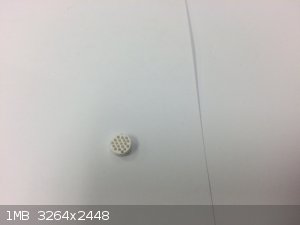
I used the same firing schedule that I did for the beads, and due to the very thin wall features, I think I overfired the piece a little bit. It
wasn't quite as porous as the beads, but still soaked up enough platinum solution to give a good coating.
|
|
|
wg48
National Hazard
Posts: 821
Registered: 21-11-2015
Member Is Offline
Mood: No Mood
|
|
That’s impressive work given its 0.25in dia.
Borosilicate glass:
Good temperature resistance and good thermal shock resistance but finite.
For normal, standard service typically 200-230°C, for short-term (minutes) service max 400°C
Maximum thermal shock resistance is 160°C
|
|
|
Heptylene
Hazard to Others
Posts: 319
Registered: 22-10-2016
Member Is Offline
Mood: No Mood
|
|
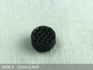
I find it impressive how dark the catalyst is colored given the small amount of platinum that is present.
After your success with the catalyst beads, I'm sure this new catalyst will work great!
I ran a quick test this afternoon at a much reduced flowrate compared to my previous attempt to see if air cooling would be sufficient to cool the
tube.
I bubbled air through about 10 % commercial ammonia solution at an air flowrate of 0.6 liters per minute. The resulting gas mixture, which should
consist of about 10 % ammonia by volume, was passed through the tube (18 mm OD, 16 mm ID) where the catalyst is located. I used a blowtorch to heat
the catalyst to red heat. The gasses coming out of the tube were brown from nitrogen oxides and after a few minutes the tube was still cool to touch
about 15 cm downstream from the catalyst. The gasses in the tube move at about 5 cm per second.
A sample of the gas was collected in flask with some water and was found to be acidic, showing that a large portion of the ammonia was converted.
Btw this 0.6 LPM flowrate is just what my cheap aquarium air pump outputs. Assuming a 100 % conversion, this should consume a few moles of ammonia per
day.
So my next step will be building a heating element for the tube to replace the blowtorch. Using a cheap lights dimmer seems to be the most cost
effective way to regulate the power going through the element. Those can be bought on ebay for $2 apparently.
|
|
|
WGTR
National Hazard
Posts: 971
Registered: 29-9-2013
Location: Online
Member Is Offline
Mood: Outline
|
|
Quote: Originally posted by Heptylene  | | So my next step will be building a heating element for the tube to replace the blowtorch. Using a cheap lights dimmer seems to be the most cost
effective way to regulate the power going through the element. Those can be bought on ebay for $2 apparently. |
I think you have an excellent idea. I recently bought both 24 and 16 gauge Kanthal heating wire from Temco Industrial. I originally used 24 gauge
wire for the tube furnace. While it works fine, it's rather flimsy when wound into a 1" diameter. I was thinking of migrating to the heavier 16
gauge wire for the added structural stability and durability. The catch is that the 16 gauge wire has very low resistance, about 0.324Ω per foot. I
figured that with a few feet I could get to 1Ω, and then use a 12V transformer for power. This would work for sure, but would require a 150W+
transformer. If I also wanted to use a dimmer, it would have to be one rated for inductive loads. Those types are several times more expensive than
the usual ones that are used to control simple resistive loads like light bulbs (or heating elements).
After thinking about it some more, it would be so much easier to just drive the heating element directly from 120VAC through a generic dimmer, and
just deal with the flimsy, higher resistance, wire. I'm being too much of a perfectionist; the current wire selection is not a problem, really. It's
not like the wire is being over-worked, or is going to fail any time soon, and you can see from the pictures that it holds its shape fairly well.
| Quote: Originally posted by Heptylene | I find it impressive how dark the catalyst is colored given the small amount of platinum that is present.
After your success with the catalyst beads, I'm sure this new catalyst will work great! |
I'm hopeful. I've got the open area of the catalyst up to about 40% of the tubing ID. That's still less than the 60% or so obtained in industry when
using platinum/rhodium wire mesh, but it's better than the 10-20% that I was getting before with the bead-shaped geometry. Hopefully this translates
into a higher maximum flow rate through the reactor, before ammonia starts passing through unconverted. Fingers crossed...
| Quote: Originally posted by Heptylene | I ran a quick test this afternoon at a much reduced flowrate compared to my previous attempt to see if air cooling would be sufficient to cool the
tube.
I bubbled air through about 10 % commercial ammonia solution at an air flowrate of 0.6 liters per minute. The resulting gas mixture, which should
consist of about 10 % ammonia by volume, was passed through the tube (18 mm OD, 16 mm ID) where the catalyst is located. I used a blowtorch to heat
the catalyst to red heat. The gasses coming out of the tube were brown from nitrogen oxides and after a few minutes the tube was still cool to touch
about 15 cm downstream from the catalyst. The gasses in the tube move at about 5 cm per second.
A sample of the gas was collected in flask with some water and was found to be acidic, showing that a large portion of the ammonia was converted.
Btw this 0.6 LPM flowrate is just what my cheap aquarium air pump outputs. Assuming a 100 % conversion, this should consume a few moles of ammonia per
day. |
That is very cool. So I suppose that you're not having any trouble with the tubing melting anymore? Are you noticing any ammonia getting past the
catalyst at that flow rate? It seems that moisture condensing on the tubing is normal, but the tell-tale evidence of ammonia is if there is a fog of
ammonium nitrate at the output. Air cooling would certainly be preferable over water cooling if for no other reason than simplicity. I may try that
as well, although with a condenser I can manipulate the temperature at will for testing purposes.
I did notice from my temperature measurements that both my furnace and condenser are considerably larger than they need to be. I'm going to try
shortening the furnace by half, and the condenser down to about 20cm (8") or so. Hopefully that would allow a tubing length of 2' or so, allowing
much lower shipping costs, etc.
[Edited on 9-5-2018 by WGTR]
|
|
|
WGTR
National Hazard
Posts: 971
Registered: 29-9-2013
Location: Online
Member Is Offline
Mood: Outline
|
|
Wow
I went from running a maximum of 150ml/min of air with three round catalyst beads, to 600ml/min with one honeycomb bead! And still no magic ammonia
smoke in sight! I'm pleasantly--no, ecstatically--surprised!
I stopped at 600ml/min, primarily because I didn't want to blow the catalyst down the tube. I need to think about a good way to fix it into place.
I'm reluctant to use the pill shaped pieces of ceramic that I have, because I don't want to obstruct the gas flow through the center of the catalyst.
Perhaps if I have an appropriately-sized piece of quartz tubing that will fit around the edge of the catalyst, I can use a short piece to hold it into
place that way.
I need to find some of that 10% janitorial ammonia. I think ACE carries it. Right now I'm using about 3% concentrated ammonia, and don't want to use
my ACS graded ammonia to bring it up to 9-10%...too expensive that way.
[Edited on 9-6-2018 by WGTR]
|
|
|
WGTR
National Hazard
Posts: 971
Registered: 29-9-2013
Location: Online
Member Is Offline
Mood: Outline
|
|
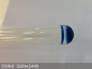
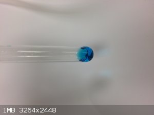
The Blue Color of Dinitrogen Trioxide
No, the solution isn't gravity-defying, for some reason the picture just loaded sideways.
One thing that I’ve noticed when running my Ostwald reactor, is that a lot of moisture is produced:
4 NH3 + 5 O2 → 4 NO + 6 H2O [1]
That’s to be expected with so much hydrogen being present in the ammonia. This may seem desirable; after all, we need water to produce the acid.
One problem is that more water is produced in the reaction than we really need for this overall reaction:
4 NO2 + O2 + 2 H2O → 4 HNO3 [2]
Basically we have three times more water than needed.
A second problem is that the overall reaction to nitric acid doesn’t occur in one step. First nitric oxide is oxidized to nitrogen dioxide in air:
2 NO + O2 → 2 NO2 [3]
This is a relatively slow reaction, taking seconds, minutes, or days depending on concentration. At extremely dilute concentrations this reaction may
effectively never complete. The reaction with water is somewhat complicated, but is
3 NO2 + H2O → 2 HNO3 + NO [4]
overall under the conditions of bubbling the dilute gases through warm water or concentrated nitric acid. This reaction is reversible, and by
bubbling nitric oxide through concentrated acid, nitrogen dioxide can be reformed and stripped away, diluting the acid with water. Thus it is
important to ensure that ample time is given for [2] to occur in order to obtain the maximum concentration of nitric acid. Nitrous acid is an
intermediate that forms during the overall reaction of [4]:
2 NO2 + H2O → HNO3 + HNO2 [5]
Nitrous acid can either disproportionate and form nitric oxide and more nitric acid:
3 HNO2 → HNO3 + 2 NO + H2O [6]
or under very cold conditions can form the anhydrous dinitrogen trioxide:
2HNO2→ N2O3 + H2O [7]
The same compound can be formed directly from partially oxidized nitric oxide below 0°C:
NO + NO2 ⇌ N2O3 [8]
The chemistry of nitrogen oxides and water is quite complicated, and I’m not doing it justice. The book “Absorption of Nitrous Gases” is in the
Sciencemadness library, and dedicates a generous number of pages to the topic.
Anyway, armed with the previous information, I plan to make some changes to the reactor design, and borrow some ideas from Heptylene in the process.
Recently I ran some clear PVC tubing from the condenser output to a container filled with ice, with the intention of lowering the vapor pressure of
water enough to remove most of it from the product gases. This kind of thing has to be done quickly after the ammonia oxidation reaction takes place,
so that most of the NO does not have enough time to oxidize to NO2. NO does not react with water by itself, while NO2 does.
Without removing moisture with this ice bath condenser, moisture gradually reacts in [5] downstream. One byproduct of this reaction is the generation
of heat, which in turn causes the acid product to vaporize. This mist gets carried along, where it deposits as a thin film on pretty much everything
downstream.
Even with my overly-long condenser, I was still able to remove almost all of the moisture just in a couple loops of PVC tubing submerged in ice,
without losing much NO. The gases in the downstream NO oxidation chamber remained clear and brown, with no cloudiness or traces of moisture showing
up on the glass walls. Any NO that was already oxidized before hitting the ice bath was simply trapped in the tubing as dilute nitric acid.
The resultant NO2 was then led into a “cold finger”, basically just a test tube that was partially submerged in liquid nitrogen. I
happen to have large quantities of liquid nitrogen just sitting around so it’s handy to me, but dry ice, a freezing salt mixture, or running a tube
through a cold freezer might work just as well. The result was a frozen mixture of N2O4 and N2O3, a
rather pale greenish solid. Letting it warm up somewhere below 0°C allowed a rather pale-green liquid to gather at the bottom of the test tube.
Slowly adding a few drops of water (this is exothermic, so this has to be done gradually, and with cooling, to keep the mixture around 0°C), caused
the formation of two layers, one clear, and another one deep blue. The deep blue layer is quite dense and is primarily N2O3,
whereas the upper layer is concentrated nitric, up to 60-70%, with possibly some N2O4 still dissolved in it. It is not possible
to obtain greater than 60-70% nitric by only adding water to cold N2O4, because of the equilibrium that is established between
nitric acid and N2O3. If 100% acid is desired, oxygen gas can be introduced to the mixture, and the blue
N2O3 layer will slowly disappear as it oxidizes and forms more nitric acid. If red fuming acid is desired, less water is added
than theoretically required, while adding oxygen.
Getting back to my planned design changes, I think that Heptylene has a good idea, and that a water condenser isn’t needed on the quartz reactor
tube itself. The tube cools down below 300°C in air before even 15-20 cm or so. Kapton tape is usable up to 300°C, and I think that it’s
possible to join the quartz tube to a length of borosilicate or soda-lime tubing while the gases are still fairly hot, by wrapping the joint with
Kapton. The advantage to this is that even borosilicate tubing is pretty easy to shape over a propane torch, and can be shaped into a “U” or
something that can be submerged in ice. An additional advantage is that I would feel more comfortable turning my back to something like this while
it’s running, because I wouldn’t have to worry about the drain backing up in the condenser and running water out under the door into the hallway,
if you know what I mean. Finally, it would allow a pretty short tubing length after the reactor, allowing minimal loss of NO to oxidation in the ice
bath. Further design details need to be worked out in the lab.
|
|
|
Morgan
International Hazard
Posts: 1660
Registered: 28-12-2010
Member Is Offline
Mood: No Mood
|
|
Some tibits in the link maybe of interest .. perfecting the industrial process.
"Under the strongly oxidizing conditions of the Ostwald process, considerable quantities of volatile platinum oxides, primarily platinum dioxide, are
formed which are carried off by the gas flow and thus can lead to high precious metal losses during the course of typical process campaigns lasting
several months. In the 1960s it was found that palladium gauzes installed beneath the platinum gauzes (gas stream from above) can catch, i.e. reclaim,
a large proportion of the platinum. Initially, palladium-gold alloys were used for the catchment gauzes, in particular PdAu80/20. However, since the
1980s the alloy PdNi95/5 has been used almost exclusively. The catchment of platinum is presumably achieved via an exchange reaction between the
platinum dioxide in the gas phase and metallic palladium resulting in the formation of palladium oxide. The value of the palladium lost in this way is
normally considerably less than the value of the reclaimed platinum."
http://www.chemgapedia.de/vsengine/vlu/vsc/en/ch/25/heraeus/...
|
|
|
Heptylene
Hazard to Others
Posts: 319
Registered: 22-10-2016
Member Is Offline
Mood: No Mood
|
|
@WGTR
Kapton tape! I knew that some gas chromatography columns (which are heated in an oven) were made of polyimide, but I had no idea that there existed
polyimide tape! Since I have 3 pieces of quartz tube (18x500 mm) I could always join them if needed in the future. Or join a borosilicate condenser
for that matter.
I should take a look at that book on nitrous gasses, looks interesting and directly relevant to what we're doing.
@Morgan
I had always thought of the catalyst as something that would not deteriorate. Let's hope this loss of platinum will not be too significant for an
amateur reactor. Depositing additional platinum won't be expensive given the small quantities needed, but might be time-consuming if it has to be done
too often.
|
|
|
Chemetix
Hazard to Others
Posts: 375
Registered: 23-9-2016
Location: Oztrayleeyah
Member Is Offline
Mood: Wavering between lucidity and madness
|
|
"Basically we have three times more water than needed.
A second problem is that the overall reaction to nitric acid doesn’t occur in one step. First nitric oxide is oxidized to nitrogen dioxide in air: "
This was what I found to be the limit of the concentration available from a simple NH3 oxidation, I was getting a crude value of 8M from the first
condensation. The answer I suspect is a long length of black irrigation tube 30 or 60 meters long in a coil, and about 25mm dia for long residence
times for the oxidation to NO2 and the subsequent reaction with water to re-emit NO in a iterative sequence towards full absorption.
As for concentrating the acid once made, does a distillation from calcium nitrate seem a reasonable way to break the azeotrope with water? Seems a
little easier than working with semi cryogenic oxidations with oxygen and N2O3 with water. Although the chemistry has always fascinated me since
reading about N2O4 as a rocket oxidant, The image of blue N2O3 is really amazing.
|
|
|
WGTR
National Hazard
Posts: 971
Registered: 29-9-2013
Location: Online
Member Is Offline
Mood: Outline
|
|
| Quote: Originally posted by Chemetix | This was what I found to be the limit of the concentration available from a simple NH3 oxidation, I was getting a crude value of 8M from the first
condensation. The answer I suspect is a long length of black irrigation tube 30 or 60 meters long in a coil, and about 25mm dia for long residence
times for the oxidation to NO2 and the subsequent reaction with water to re-emit NO in a iterative sequence towards full absorption.
As for concentrating the acid once made, does a distillation from calcium nitrate seem a reasonable way to break the azeotrope with water? Seems a
little easier than working with semi cryogenic oxidations with oxygen and N2O3 with water. Although the chemistry has always fascinated me since
reading about N2O4 as a rocket oxidant, The image of blue N2O3 is really amazing.
|
The idea of using irrigation tubing is an interesting one. I wonder if it would hold up OK to the acid? I think that for it to work right, pure
water would have to be added at one end, and the nitrous gases would have to be piped in at the other, such that both were flowing in opposing
directions. That way the most concentrated nitrogen dioxide meets the most concentrated acid just before it leaves the tube, and the weakest acid
interacts with the weakest leftover gas concentration. That's how it's done in industry, and should give the highest acid concentration.
It sounds like you were getting about 50% acid, if my brain is working correctly at this time of the night. That's not bad at all. I'm not prepared
to say much about distillation with nitrate salts, as I've never tried it.
While I'm thinking about it, I'd like to mention some thoughts on running the reactor continuously, rather than loading fresh ammonia solution as a
batch process. I'm currently bubbling air through ammonia of a specific concentration and temperature in order to obtain a specific ammonia/air
mixture. This seems to work fine over a period of several hours. Ammonia is gradually stripped out of solution as time goes on however. In order to
replenish what is removed, I'm thinking of an ammonia generator with urea and sodium hydroxide, with the ammonia output mixed directly with the air
feed. Of course, under these conditions the ammonia/air mixture is unknown, as it proves difficult to control the exact parameters of the ammonia
generator. What I suggest, is then taking this gas mixture and bubbling it through the ammonia solution as is already being done. The ammonia
solution then acts as an ammonia reservoir. The generator can run for a few hours, during which the ammonia solution slowly increases in
concentration as the gases bubble through it. When the generator is turned off, the ammonia concentration slowly decreases as the air strips it from
solution and carries it to the reactor. Momentary surges or interruptions in ammonia production would have no affect on the operation of the reactor
with this type of setup. An added benefit is that with the generated ammonia being mixed directly with air before bubbling it through ammonia
solution, suck-back is prevented.
| Quote: Originally posted by Heptylene | @WGTR
Kapton tape! I knew that some gas chromatography columns (which are heated in an oven) were made of polyimide, but I had no idea that there existed
polyimide tape! Since I have 3 pieces of quartz tube (18x500 mm) I could always join them if needed in the future. Or join a borosilicate condenser
for that matter.
I should take a look at that book on nitrous gasses, looks interesting and directly relevant to what we're doing.
@Morgan
I had always thought of the catalyst as something that would not deteriorate. Let's hope this loss of platinum will not be too significant for an
amateur reactor. Depositing additional platinum won't be expensive given the small quantities needed, but might be time-consuming if it has to be done
too often. |
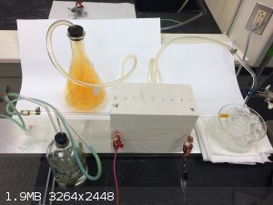
Yes, Kapton is like some kind of miracle tape! Here, I made some changes to the reactor design this evening. The furnace was cut in half (9" long
now), and the water condenser was removed and replaced with some borosilicate tubing in an ice bath. The quartz reactor tube is joined to the
borosilicate tubing with Kapton tape. The boro was wound into a spiral condenser by hand (easy with a propane torch). Power input to the furnace was
cut from 300W to 150W, saving energy. It could probably be less than half of this if I insulated things better. I keep the furnace running at bright
red. Right now the catalyst is the honeycomb type, with a 300ml/min air flow rate, and an ammonia solution of 6% concentration. The tubing has 7mm
ID, the same as before. I believe it is possible for someone to use a 12" long quartz tube in this application, meaning that it should not be so
expensive for people to obtain this.
I looked at my earlier temperature profile measurements to determine how much quartz tubing length I needed outside of the furnace before the Kapton
joint. Right now I have it at about 4" of spacing, and the joint stays barely warm to the touch. The Kapton seems to be holding up OK.
Unfortunately, I didn't realize that I've been working on this project for a month and a half now. I'm getting very behind on some other stuff, and
need to move on after the end of this weekend. Are there any questions about my current setup, requests for better pictures, etc? I'm hoping that
there is enough information in our posts at this point, between you, Chemetix, others, and myself, for someone else to put something together and get
it working.
Here's some home-made copper nitrate:
|
|
|
Chemetix
Hazard to Others
Posts: 375
Registered: 23-9-2016
Location: Oztrayleeyah
Member Is Offline
Mood: Wavering between lucidity and madness
|
|
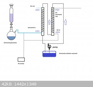
The Ammonia generator has been one of those things that roll around in my mind as I come up with a better way of doing it. You are getting close to
my idea of running an absorption tower and stripping tower with some sort of reservoir of fluid to keep the fluctuation of concentrations to a
minimum.
Two towers with a vigreaux style mixing surface running vertically with a fluid pumped from the bottom of the first tower to the top of the second
tower and back via the reservoir to the first tower again in a closed loop.
Gas from an ammonia generator gets directed into the bottom of the first tower and and absorbed. Air gets pumped into the bottom of the second tower
where a constant stream of dilute ammonia exits the top of the second tower to be fed into the oxidiser.
This was going be a way of bypassing the CO2 from the urea decomposition reaction and still keep the reactor running fairly constantly even when a
urea batch gets changed. But any ammonia generating reaction could feed the scrubbing column.
|
|
|
Morgan
International Hazard
Posts: 1660
Registered: 28-12-2010
Member Is Offline
Mood: No Mood
|
|
I was wondering if you etched the inside of a quartz tube with bifluoride if you could get the platinum catalyst to stick to it, as a way to increase
the output or yields?
As an aside, it might be fun to construct a Döbereiner lighter with the platinized ceramic or a lighter using the ceramic beads and fine platinum
wire ignited using methanol vapor.
"Humphry’s cousin Edmund Davy, working at the Cork Institution, was then carrying out a series of researches on the chemistry of platinum. In the
course of this he found that platinum sulphate could be reduced by alcohol to platinum in finely divided form. The platinum powder, Davy observed,
reacted strongly with alcohol vapour at room temperature, remaining white hot until all the alcohol was consumed. “This mode of igniting metal”,
he remarked, “seems to be quite a new fact in the history of chemistry; but the means of keeping it in a state of ignition is only another
illustration of the facts previously pointed out by Sir H Davy” (2).
"On 3rd August Döbereiner produced an even more striking version of his experiment. Instead of the previous static arrangement, he directed a fine
jet of hydrogen at the platinum from a distance of 4 cm, so that it was mixed with air before reaching its target. This had the effect of making the
platinum immediately white hot and igniting the hydrogen jet. More excited letters were dispatched, commenting that “this experiment is most
surprising and amazes every observer when one tells him that it is the result of a dynamic interaction between two types of matter, one of which is
the lightest and the other the heaviest of all known bodies” (4).
"The warmth of this appraisal becomes all the greater when one considers Berzelius’ earlier low opinion of Döbereiner. In July 1821 he had
commented to Gaspard de la Rive, professor of chemistry in Geneva, “I do not know whether he (Thomas Thomson) or Döbereiner in Germany is the worst
chemist in existence at the moment” (12). On 30th October 1823, however de la Rive found himself grudgingly writing to Berzelius: “We have had
nothing new here since Döbereiner’s experiment with his platinum; in view of the reputation of the said Döbereiner we were sceptical of it; it is,
nonetheless, true” (13).
"By 1828 some 20,000 Döbereiner lighters were in use in England and Germany alone, and it eventually found its way into most European countries. In
spite of the invention of the safety match in 1848 by one of his former students, R. C. Böttger, the Döbereiner lighter was still in use at the
beginning of the First World War. Part of its attraction lay in the scope it offered to the imaginative decorator: Döbereiner himself suggested that
one could “embellish it with two alchemical symbols, namely the lion and the snake, and so arrange it that the snake takes the place of the
capillary tube for the stream of hydrogen and the open jaws of the lion sitting opposite the snake hold the platinum” (15).
The Pivotal Role of Platinum in the Discovery of CatalysisThe Pioneering Work of Johann Wolfgang DÖbereiner During the 1820s
https://www.technology.matthey.com/article/30/3/141-146/
|
|
|
Heptylene
Hazard to Others
Posts: 319
Registered: 22-10-2016
Member Is Offline
Mood: No Mood
|
|
I just ordered some nichrome wire and a very cheap light dimmer on ebay. This should become a high temperature pre-heating sleeve for the reaction
tube.
I've tried to make more catalyst by the method you used WGTR: pyrolysis of hexachloroplatinic acid. However I only have potassium hexachloroplatinate,
which doesn't decompose below about 500 °C from what I've seen. This is not a careful measurement because I don't have a high temperature furnace nor
a high temperature thermometer. Rather I dipped a piece of silica in a solution of the salt and placed it inside a beaker on my hotplate. I oberseved
almost no decomposition at the max temperature of my hotplate: 500 °C.
In a propane flame the decomposition is much more complete (dark deposit of Pt), but this has the side-effect of weakening the silica fiber and making
it brittle.
So I'm currently making some hexachloroplatinic acid, which should be easier to decompose.
@Chemetix I'm not sure I understand the setup you propose for generating the ammonia/air mixture. Are the two columns on top of each other or are they
separate? Could you provide a drawing?
|
|
|
WGTR
National Hazard
Posts: 971
Registered: 29-9-2013
Location: Online
Member Is Offline
Mood: Outline
|
|
Yeah, the ammonium salt has the advantage that there's no leftover residue other than platinum itself. It's worth the extra effort to make it, and a
100ml bottle of the weak solution should last you forever. I used ethyl alcohol as a solvent. I don't know how much effect that has on how easy the
salt is to reduce later since I didn't try using water as a solvent, and my catalyst support was also quite absorbent.
I did find some high silica content wool in the lab, but I personally wasn't too happy with it. It felt like fiberglass, and after being heated with
a propane torch became very brittle and friable. The stuff just broke into pieces just the right size to make hands and lungs itchy.  If you don't mind me asking, what country are you located in? If you don't mind me asking, what country are you located in?
If you can't get some insulative firebrick, then perhaps some ceramic wool would work. You could ask Chemetix what he was using. I think you'll need
some kind of insulation, although you could compensate by using lots of power in the heater.
Chemetix, I'm not sure that I understand your idea either, but it's probably because I'm either making or not making certain assumptions about it.
Could you describe the theory behind how it should work?
For the benefit of people reading, be careful handling platinum salts. The cautions about platinum salts being strongly sensitizing for people are no
joke. Gloves are recommended. This stuff can sensitize people to various skin ailments at any time in their lives. Certain people are genetically
predisposed towards skin sensitivities. I've known people who lived a good part of their lives with no problems, and then got some cleaning chemicals
under a ring one day, developed a rash on the entire hand, and now randomly battle severe skin rashes than can only be mitigated with strong topical
steroids, years later. Just practice good lab hygiene and one should be fine.
|
|
|
Heptylene
Hazard to Others
Posts: 319
Registered: 22-10-2016
Member Is Offline
Mood: No Mood
|
|
Yes the silica has a tendency to make very fine fibrous particles, I think much like those of asbestos. Those fibers are pretty damaging to the skin.
I tried to break down a piece of silica wick into separate strands and my fingers had a "fibrous" sensation at the end, like I had a lot of very small
cuts. Now I always handle silica with gloves and outside for this reason. Once the catalyst is installed this should not be a problem.
The heating element I'm going to build will be about 2 meters of 0.25 mm (30 AWG) nichrome wire coiled around the quartz tube over a distance of 10 cm
(about 33 turns). Around this I'll wrap some ceramic fiber cloth (ebay) for insulation. I must say deciding which wire gauge to use was pretty difficult. Not too fragile, but not too conductive either. 2 meters
should draw about 4-5 amps at 240 V, hence the need for a dimmer. And/or I might make the heating element longer. I'm hoping I can get high enough
temperatures without making this prohibitively expensive in electricity.
I've read about platinum being toxic by ingestion (side effect of chemotherapy and such), but after doing a bit of research it seems I had
underestimated what chloroplatinate salts can do even upon skin contact. I don't usually wear gloves, but maybe I should with this.
I live in Switzerland. A bit of a nanny state chemistry-wise, but a nice place nevertheless. WGTR I assume you are in the US?
I finished the hexachloroplatinic acid btw. I'm now to proud owner of an expensive orange solution containing 0.49 g Pt/100 ml water.
The acid decomposes much more readily than the potassium salt. Heating a piece of silica wick soaked in the solution to 500 °C on my hotplate, the
decomposition is evident by the appearence of a black deposit of platinum on the silica.
|
|
|
Chemetix
Hazard to Others
Posts: 375
Registered: 23-9-2016
Location: Oztrayleeyah
Member Is Offline
Mood: Wavering between lucidity and madness
|
|
I'll get a schematic up describing the scrubbing tower idea, but first, a note with fibers. They were my first attempt and they just melt into a lump.
They lose their surface area almost instantly and they don't hang onto the metals very well. I hope you have more success but I'm not optimistic.
|
|
|
Chemetix
Hazard to Others
Posts: 375
Registered: 23-9-2016
Location: Oztrayleeyah
Member Is Offline
Mood: Wavering between lucidity and madness
|
|
The ammonia scrubbing tower idea needed a bit of a diagram it seemed. So, have a look at the schematic and tell me what you think.
|
|
|
Heptylene
Hazard to Others
Posts: 319
Registered: 22-10-2016
Member Is Offline
Mood: No Mood
|
|
Thanks for the schematic, the absorption and stripping towers make sense now. So what happens is the tower to the right removes most of the ammonia
from the solution dripping downward, and this "stripped" solution is replenished by absorption of the ammonia coming from the gas generator through
the left tower, correct?
And I'm guessing the absorption would be very efficient given the counter-flow of ammonia gas and dilute ammonia. Really nice design, although
probably a whole project on its own.
I'd like to start from 25 % ammonia solution because I could get 20 liters easily. As stupid as it sounds, I can't find a cheap source of urea where I
live. Local gardening shops don't have it it in large bags it seems, or they sell it for some ridiculous price for a small quantity.
Now the problem with ammonia solution is that bubbling air through it lowers the concentration progressively, and therefore changes to the composition
of the ammonia/air feed to the reactor. In fact for solutions of ammonia below 10 %, the vapor pressure of ammonia above the solution is almost
proportional to the concentration of the solution (ammonia data page). So what I'd like to find a way to strip the solution while keeping a constant gas feed composition.
One way to do this would be to simply drip ammonia solution inside a hot kettle at a controlled rate (peristaltic pump) and with a controlled air
flowrate removing the vapor from the kettle. The gas coming out of the kettle would have a constant composition but would also contain a lot of water.
Furthermore this might tend to condense later before entering the reactor. Just my thoughts.
|
|
|
Morgan
International Hazard
Posts: 1660
Registered: 28-12-2010
Member Is Offline
Mood: No Mood
|
|
| Quote: Originally posted by WGTR | Yeah, the ammonium salt has the advantage that there's no leftover residue other than platinum itself. It's worth the extra effort to make it, and a
100ml bottle of the weak solution should last you forever. I used ethyl alcohol as a solvent. I don't know how much effect that has on how easy the
salt is to reduce later since I didn't try using water as a solvent, and my catalyst support was also quite absorbent.
I did find some high silica content wool in the lab, but I personally wasn't too happy with it. It felt like fiberglass, and after being heated with
a propane torch became very brittle and friable. The stuff just broke into pieces just the right size to make hands and lungs itchy. If you don't mind me asking, what country are you located in?
If you can't get some insulative firebrick, then perhaps some ceramic wool would work. You could ask Chemetix what he was using. I think you'll need
some kind of insulation, although you could compensate by using lots of power in the heater.
Chemetix, I'm not sure that I understand your idea either, but it's probably because I'm either making or not making certain assumptions about it.
Could you describe the theory behind how it should work?
For the benefit of people reading, be careful handling platinum salts. The cautions about platinum salts being strongly sensitizing for people are no
joke. Gloves are recommended. This stuff can sensitize people to various skin ailments at any time in their lives. Certain people are genetically
predisposed towards skin sensitivities. I've known people who lived a good part of their lives with no problems, and then got some cleaning chemicals
under a ring one day, developed a rash on the entire hand, and now randomly battle severe skin rashes than can only be mitigated with strong topical
steroids, years later. Just practice good lab hygiene and one should be fine.
|
Platinosis from Wiki
"Halogeno-platinum compounds are among the most potent respiratory and skin sensitisers known, therefore it is vital that exposure via the skin and by
breathing contaminated air is carefully controlled."
"In practice, the compounds mainly responsible for platinum sensitisation are typically the soluble, ionic, platinum-chloro compounds such as ammonium
hexachloroplatinate and tetrachloroplatinate, and hexachloroplatinic acid. Other ionic halogeno compounds are also sensitisers, the order of
allergenicity being Cl > Br > I."
|
|
|
WGTR
National Hazard
Posts: 971
Registered: 29-9-2013
Location: Online
Member Is Offline
Mood: Outline
|
|
| Quote: Originally posted by Heptylene | | The resulting gas mixture, which should consist of about 10 % ammonia by volume, was passed through the tube (18 mm OD, 16 mm ID) where the catalyst
is located. |
Can you measure the inside of the tube, and make sure that it's 16mm? 16mm should be 0.630", and 5/8" is 0.625". If you have a 5/8" bit, can you see
if it slides (care)fully through the quartz tube? Sorry for the cryptic question. I'm going to be in the lab this weekend, and I may try
"something".
| Quote: Originally posted by Heptylene | | I live in Switzerland. A bit of a nanny state chemistry-wise, but a nice place nevertheless. WGTR I assume you are in the US?
|
Yes, in Texas.
Congratulations on your proud new ownership of some hexachloroplatinic acid. Yours is about 5 times more concentrated than mine. A little bit goes a
long way.
Chemetix, what did you use to draw that illustration? It looks pretty neat.
I'm thinking of an ammonia generator that is probably not very fancy by comparison: An ammonia solution drips slowly into a stoppered bottle that is
partially full of dry calcium oxide. The quicklime removes the water and produces dry ammonia gas, which is then led out through a glass tube into a
second bottle that is empty. The air supply is also led into this second bottle (or "T" fitting, etc.) where the two gas feeds mix together (they
don't have to mix particularly well at all). A third tube exits from this second bottle, and is led into a third bottle where the gases are bubbled
with an air stone through an ammonia solution. The gases that leave the third bottle can be led into a fourth bottle, which can either be empty or
full of calcium oxide. After enough air has been bubbled through the ammonia solution, I've noticed that water droplets can start building up inside
the tube that is leaving the bottle. If enough water gets in the wrong place, it's possible for a water droplet to get pushed into the hot reactor.
The fourth bottle would simply collect these droplets, and keep them from proceeding further.
The first bottle produces dry ammonia gas under its own vapor pressure. The second bottle is only for mixing of the air and ammonia. The third
bottle absorbs the ammonia produced in the first bottle, and releases a fixed ammonia/air mixture that is dependent upon its own ammonia solution
concentration. The fourth bottle is a water trap and/or a drying train.
Basically (no pun intended), the reactor can be run for several hours without the ammonia generator running. Only when the concentration in the third
bottle starts dropping off, is it necessary to "recharge" it by turning on the ammonia generator.
|
|
|
Chemetix
Hazard to Others
Posts: 375
Registered: 23-9-2016
Location: Oztrayleeyah
Member Is Offline
Mood: Wavering between lucidity and madness
|
|
"Chemetix, what did you use to draw that illustration? It looks pretty neat."
Good ol' MS paint. It's quick, light and easy to use.
"The first bottle produces dry ammonia gas under its own vapor pressure. The second bottle is only for mixing of the air and ammonia. The third bottle
absorbs the ammonia produced in the first bottle, and releases a fixed ammonia/air mixture that is dependent upon its own ammonia solution
concentration. The fourth bottle is a water trap and/or a drying train."
Such a simple solution really, I like it. I think the third bottle just needs a hydrometer to show the density of the solution in real time. My set up
could ultimately change the flow rate down the ammonia stripping tower to keep the output of ammonia pretty constant. But it is semi industrial in
terms of the amount of variables that need controlling and the amount of setup. But it would be a nice way of absorbing ammonia formed by a low
pressure Haber system. N2 and H2 cycling around once the ammonia has been stripped out.
I think this would be an amazing achievement to have a bench top Haber to nitric acid system working.
|
|
|
Heptylene
Hazard to Others
Posts: 319
Registered: 22-10-2016
Member Is Offline
Mood: No Mood
|
|
@Chemetix: I like the idea of an hydrometer, I'll keep that in mind when building the ammonia generator.
@WGTR: I don't have a caliper to measure the ID of the tube, but using a ruler I can say its at least close to 16 mm. Not 15 nor 17 mm. Why do you
need a precise measurement of the ID?
The setup you propose would be useful to regulate the composition of the gas feed. One thing I don't like about it is the use of calcium oxide, which
is consummed and has to be bought, or regenerated by heating Ca(OH)2 in a furnace. This could get expensive in the long run. But for testing purposes
this should be a pretty stable source of gas.
The same idea could be used if, for instance, the gas generator is a 25 % ammonia solution.
I had originally intended to dilute 20 liters of 25 % ammonia to 50 liters of (approx.) 10 % solution and use that directly. But this would be
wasteful as the solution would become too dilute at some point, wasting the remaining ammonia unless there was a way to concentrate it. If "too
dilute" is a concentration below say 5%, then half the ammonia would go to waste. Fractional distillation could be used,but this would be
time-consuming.
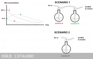
Instead ammonia gas could be stripped from the 25 % solution (call it "A") with air and absorbed through 10 % solution (call it "B") and fed into the
reactor. If solutions A and B have about the same volumes, solution A should be progressively depleted and solution B should be enriched in ammonia
and then be depelted too.
I made a drawing of the concentration curves vs time for both solutions (A and B). This is scenario 1. The drawing isn't pretty but should get the
point across. The curves are only intended to show the general trend.
If instead one uses a 10 % solution only, the depletion should be much more rapid (Scenario 2 , solution B*).
I hope this makes sense, its late and my mind a bit foggy.
|
|
|
WGTR
National Hazard
Posts: 971
Registered: 29-9-2013
Location: Online
Member Is Offline
Mood: Outline
|
|
I like the idea of a hydrometer as well; I hadn't thought of that yet. It's certainly much more practical than monitoring it with other means, and
should be very robust. If one wanted to, it would seem possible to make one with a float switch of sorts, that would turn on or turn off the ammonia
generator automatically as needed.
OK, I agree that using calcium oxide is an unnecessary added materials cost. Looking at your illustration, one way to improve it would be to add heat
to solution "A". This will lower the partial pressure of air, and raise the partial pressures of ammonia and water. Referring to Wikipedia's ammonia data page, the ammonia vapor pressure of a 10% solution at 20°C is roughly the same as a 3% solution at 50°C.
A 3% solution at 50°C has roughly equal amounts of ammonia and water vapor. Since ammonia and water are roughly equal in molecular weight, if
condensed at a cold enough temperature would give a roughly 50% ammonia solution (not accounting for a density of less than 1), way more than 10%.
The idea is, that a hydrometer could be used with some kind of float switch, that would turn on a heater for solution "A". The ammonia and water
vapor would be absorbed in solution "B" at 20°C until the density was low enough, at which point the heater would turn off. Every now and then some
solution would have to be removed from solution "B" and put into solution "A" to account for water migrating from "A" to "B".
I'm asking about the tubing ID because I'm entertaining the idea of making a catalyst support for you. I want to make sure that I don't make it
unnecessarily small, but I want to account for thermal expansion of the ceramic as well, since silica doesn't expand much when heated. I had a rough
weekend and didn't have time to try anything yesterday, but I have some new ideas for making the support, and may be able to shape the green clay with
a CNC mill.
|
|
|
| Pages:
1
2
3
4 |
|


