| Pages:
1
2 |
yobbo II
National Hazard

Posts: 709
Registered: 28-3-2016
Member Is Offline
Mood: No Mood
|
|
Balance repair
I obtained a 0.0001g resolution balance that is not working.
There seems to be something wrong with the electrics (internal computer or display electronics).
The physical end seems to be ok.
I thought I might simply put an input to the sensor and read output using an instrumentation amplifier?
What sort of input do these things take for the sensor?
Anyone any info. thoughts or leads?
TIA,
Yob
|
|
|
unionised
International Hazard
Posts: 5102
Registered: 1-11-2003
Location: UK
Member Is Offline
Mood: No Mood
|
|
It's possible that the balance uses an electromagnet to lift the weight until a "flag" is moved out of the gap between the photodiode and the LED.
The current needed to do that is proportional to the force needed.
A bit like this
https://ua-channel.com/vision/measure-the-mass-of-an-eyelash...
Do you have a compass? Is there a magnet in the balance ?
|
|
|
yobbo II
National Hazard
Posts: 709
Registered: 28-3-2016
Member Is Offline
Mood: No Mood
|
|
Thanks for reply Unionised.
Yes there are magnets according to the compass.
I have four wires going into the unit with the magnets. Where would I start?
Yob
|
|
|
yobbo II
National Hazard
Posts: 709
Registered: 28-3-2016
Member Is Offline
Mood: No Mood
|
|
Got back to this:
Got back to this as I think I need it for some density measurements. The old triple beam ohaus .1 gram resolution is not up to the job.
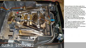
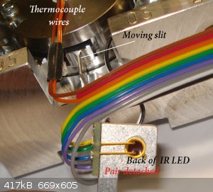
The orange and brown wires going into the top of the 'round thing' (a coil/force tranducer I presume). is just a thermocouple so I will be ignoring
that for the time being.
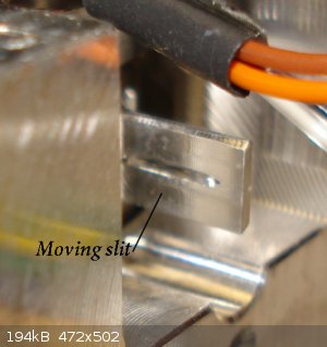
The other two wires going into the coil (it has magnets in it according to a compass) move the scales tray (where you put the stuff to be weighed) up
against the spring. I presume the scales works by putting a current into the coil to line up a moving slit that is between an IR LED and a photosensor
and then reads the current needed to keep it there.
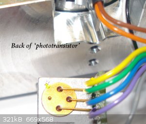
The LED/PHOTOSENSOR at the back is the mystery.
Two wires (yellow and grey) go to a IR LED which produces IR light when 10mA or so passes through it. I can see the IR with a camera.
The 'phototransistor' or photosensor is the problem. I don't actually know if it is a phototransistor. It has quite a large glass front (as far as I
can see). I cannot get a good look at it because it is inside its holder very close to the LED. I am reluctant to unsolder and try to prise it out.
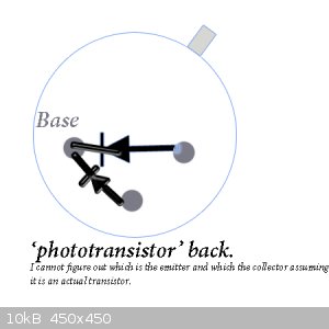
With a diode meter I can get two diodes as per the picture so it looks like a an PNP transistor. But I thought the 'base' in photo transistors did not
come to the outside but that photons falling on it did the job of the base input (from the outside connection) current.
When it is connected to a multimeter that has a 'hfe' tester it gives an output when the LED lights but I cannot figure out if its npn or pnp or were
is the collector or emitter. It's all a bit up in the air.
I am assuming that the middle connection is the base? so the middle wire stays put in the base connection on the meter.
Lets call the emitter the connection nearest the tab on the 'transistor'. I don't know which is or is not the collecctor or emitter or if I even have
a simple transistor.
When the 'transistor' is connected with the emmiter (wire nearest the tab) and collector connected 'properly' into the hfe meter I get a reading of 0
with the LED off and 5 when it is on when the NPN setting selected.
With PNP setting selected I get 1 with the LED off and 6 when the LED is on.
(I now swap the emitter and collector leads in the tester)
When 'transistor' is connected 'the wrong way around', the emitter (wire beside the tab) is in the collector socket and the collector is in the
emitter socket I get a reading of
0 with the LED off and 4 with the LED on when the NPN setting is selected and a reading of 1 with the LED off and 6 with the LED on when the PNP
setting is selected.
Anyone able to decipher that dambdable ramble!
Perhaps I need to desolder and see can I push/prise out the photosensor to see if there is any writing on it. It is a very shallow packaging. It would
have less height than a BC 109 but is larger in diameter and the front is all glass (its looks delicate).
I could perhaps measure the voltages going to the sensor/LED pair assuming the boards driving them are not defunct. I had not thought of this before.
Perhpas I should get a new sensor pair or could I just observe the position of the slit and read weight that way. The sensor pair has not got a
position of absolute precision as you can tell from the screws that hold them is position. Once positioned and screwed down they would of course have
to stay put and not move around.
Yobbo
|
|
|
Sulaiman
International Hazard
Posts: 3558
Registered: 8-2-2015
Location: 3rd rock from the sun
Member Is Offline
|
|
Try metering the three terminals vs. the case (yellow wire) to see if anything interesting.
also, maybe the detector is a dual photodiode ? (analogue balance of photocurrent, not just on/off)
CAUTION : Hobby Chemist, not Professional or even Amateur
|
|
|
unionised
International Hazard
Posts: 5102
Registered: 1-11-2003
Location: UK
Member Is Offline
Mood: No Mood
|
|
I suspect that, as Sulaiman has suggested, the"phototransistor" is actually two photodiodes in the same package.
can you get a picture of it from the "front"?
Or can you measure the voltages across the pairs of pins, both in the dark, and in the light?
Don't risk"forcing " it to get it out of its position. It's very hard to replace a component if you don't know what it is.
A double photodiode has the advantage that you can move the balance beam until the light shining on the two diodes is equal.
That's easier to maintain than a fixed level of light- less dependent temperature and the current through the LED etc.
|
|
|
yobbo II
National Hazard
Posts: 709
Registered: 28-3-2016
Member Is Offline
Mood: No Mood
|
|
Will try with a tiny mirror to get picture of front.
The scales in question are a p-114 Denver
It measures up to 100g at 0.0001g resolution.
Thanks,
Yob
|
|
|
OldNubbins
Hazard to Others
Posts: 136
Registered: 2-2-2017
Location: CA
Member Is Offline
Mood: Comfortably Numb
|
|
The photodiodes/transistor are probably working with the load cell and thermocouple for temperature compensation and position verification in order to
achieve the higher accuracy. I would actually be checking those components last. The first thing I would do is take a very close look at the circuit
board for anything suspicious, burnt components, cracked or cold solder joints, solder whiskers, discoloration on any IC's. It could be something as
simple as the LCD/LED display output. Follow the circuit with a magnifying glass or loupe from the power input and just look for anything out of
place.
edit: have you tried adjusting the brightness or contrast of the display? I have torn things apart only to find the display needed adjustment....
[Edited on 11-16-2020 by OldNubbins]
|
|
|
yobbo II
National Hazard
Posts: 709
Registered: 28-3-2016
Member Is Offline
Mood: No Mood
|
|
The display shows garbled stuff. Nothing sensible.
There is no load cell, it is a coil of some sort that when you put about one mA into it, it moves a pivot to its position that is opposite of where
it usually sits. It moves very very little to go from one 'extreme' to the other. It moves the 'slit' that we are talking about (between the LED and
Photosensor) over the LED and sensor.
I do not think I can repair the device. There are a number of very complicated multilayer boards. I could be lucky and will have a look.
I thought I could get a working balance with a precision current supply going into the coil and the LED/Phototransister (if it is) functioning. The
weight is simply the current needed to put the balance pivit in the 'middle'. The slit positioned where the Photosensor sees the LED. I believe I
could actually do away with the LED/Photosensor and visually monitor the position of the pivot. The only thing IMO that you need to measure is the
current going into the coil.
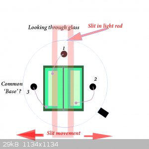
To get back to the photosensor a picture is attached.
Not a hope of getting a picture.
The diagram above is what I see when I magnify and look in at an angle. The slit and slit movement is superimposed on the diagram.
There is no connection to the case of the device not even to earth. It must be insulated with a sleve. There are only three connections to the photo
device. All five wires coming from the PCB are accounted for. Two the LED, three the photo sensor device (the 'phototransistor').
From the diagram above looking through the front of the device (at an angle) the 'diodes' go from pin 1 to 3 and from pin 2 to 3.
Using a multimeter diode checker, with each diode, I get around 520 on the display when forward biased and zero when reverse biased. It does not
matter if the LED is on or off I still get these values (ie. no response from the 'diodes' to the LED). I can see the LED working OK with a camera. I
keep ambient light away from the photosensor.
I check one diode at a time, perhaps I should wire up the two at the same time?
Might there actually be electronics in the device? I mean would/could the wires be something like 1 = minus 2 = + and 3 = output (or something like
that).
I will wire up the 'diodes', both at the same time in series with a resistor and see what happens as opposed to 'testing' them one at a time with the
diode tester of the multimeter.
If I could get the thing to weigh things to three decimall places (as opposed to four which it is made to do) that would be great.
Thanks for you time.
Yob
[Edited on 17-11-2020 by yobbo II]
|
|
|
Sulaiman
International Hazard
Posts: 3558
Registered: 8-2-2015
Location: 3rd rock from the sun
Member Is Offline
|
|
Don't be too quick to hack the balance ;
The electromechanical parts seem ok and there is cpu activity.
Q1) Does the display behave the same way each time you power up the balance?
As above, look carefully for signs of failed pcb tracks, overheated or leaking components, loose connectors etc.
If any ICs are in sockets, remove and replace them to ensure good contacts.
In order, my suspects would be:
'dry' electrolytic capacitors, especially in the power supply section
failed eeprom, lcd controller ic, power management ic and rarely the cpu itself.
Try to find the reset pin for the cpu and Briefly connect to 0v
Q2) does the lcd display similarly each time you reset the cpu?
Try the above, then we can go further
................................
100 +/-0.0001 is 1ppm resolution,
100 +/-0.001 is 10ppm - which is already non-trivial electronics for EE undergraduates and most graduates,
given that temperature changes have to be compensated for.
.................
Contact the manufacturer for a repair cost estimate
CAUTION : Hobby Chemist, not Professional or even Amateur
|
|
|
OldNubbins
Hazard to Others
Posts: 136
Registered: 2-2-2017
Location: CA
Member Is Offline
Mood: Comfortably Numb
|
|
Quote: Originally posted by yobbo II  |
The display shows garbled stuff. Nothing sensible.
There is no load cell,...
[Edited on 17-11-2020 by yobbo II] |
There is, it is called a force restorative load cell and is technically a mass comparator using an EM coil and internal mass as a standard reference.
The slit and phototransistor are feedback mechanisms and are probably the least likely component to fail. If you are getting something on the display,
even if its garbage, it is most likely something on the board like Sulaiman mentioned. All it takes is some wonky voltages at the output display
driver and you can get all sorts of randomness.
|
|
|
yobbo II
National Hazard
Posts: 709
Registered: 28-3-2016
Member Is Offline
Mood: No Mood
|
|
I meant by load cell one with strain gauges.
There is no onboard power supply it is external + 5v -15 and + 15
I have checked with a loop. The three boards are multilayer, stuff both sides and complicated . There are quite a lot of electronics on each.
When 20g (roughly the weight of the pan I presume, which is absent) is placed on the mechanism it goes down to the bottom position (about one mm). It
takes 0.5mA to return the mechanism to its top position. The mechanism where the pan is located moves about 1mm and the slit moves about 2mm.
When 80 grams is placed on the mechanism it takes 5mA DC to return it to its original position (top position). I would assume that a proper
measurement of the current needed to return the mechanism to its middle position (assuming it started at its middle position, ie. the slit lined up so
that the diode(s) got equal light) would be a measurement of the weight.
It does not matter the polarity of the DC, either polarity makes the mechanism go in the up direction. I presume AC would do the job OK too?
So what is needed is a precision current supply and a readout?
Is it easier to have a precision, temp. compensated current supply and readout for AC or DC?
I would imagine it will be DC.
Connecting the photo diodes up to a power supply 10 Volts or so and a 1k resistor and reverse biasing them, I still can see no output from them with
the LED turned on and off.
Not actually hacking the scales as I can put it back to gether any time. But I do not think it will be practical sending it for repair. A cheaper one
could be had off ebay .
Yob
|
|
|
andy1988
Hazard to Others
Posts: 135
Registered: 11-2-2018
Location: NW Americus ([i]in re[/i] Amerigo Vespucci)
Member Is Offline
Mood: No Mood
|
|
I can see your preferred approach would be to re-use the sensors/housing, bypassing the dysfunctional electronics.
Since you said the display is garbled, personally I'd look for the dot matrix driver IC. Search for the model by looking at the package and writings
on the chip. I'd then read the datasheet, and determine the configuration used by measuring the voltage on power supply pins and configuration pins
(i.e. if high or low), then use that to determine how the circuit should be designed per the datasheet (expected capacitors/resistors on each pin) and
then verify those components. From this ST7565R chip for example:
| Quote: | | 8-bit parallel or 4-line SPI display data sent from the microprocessor is stored in the internal display data RAM and the chip generates a LCD drive
signal independent of the microprocessor. Because the chips in the ST7565R contain 65x132 bits of display data RAM and there is a 1-to-1
correspondence between the LCD panel pixels and the internal RAM bits... |
Edit: And if you have a logic analyzer or oscilloscope, you can verify stuff is being sent via SPI or whatever from the
microprocessor to the display chip.
Safety precautions off the top of my head: Consider using an ESD wrist strap to reduce risk of static discharge damaging chips (metal wrist strap, not
a cloth one, the cloth ones don't work well). Don't touch multiple IC pins at the same time with your multi-meter probe. And consider plugging the
things into an GFCI outlet or isolation transformer if you have one. IIRC an isolation transformer would be necessary if you're working on the
device's power supply side of things to protect both you and the scope, but I think not necessary if working on the low voltage side. The GFCI outlet
will reduce risk of hazardous shock (sometimes things happen, e.g. device chassis or other things are not isolated properly).
[Edited on 18-11-2020 by andy1988]
|
|
|
yobbo II
National Hazard
Posts: 709
Registered: 28-3-2016
Member Is Offline
Mood: No Mood
|
|
There are no electrolytic or tantanul caps.
The display board (one of three boards in the scales) has 3 T6A39 ic's, two T6A40 ic's and one T6963CFG ic all large ic's (at least 40 pins) +
some other smaller chips.
It's a bit beyond me.
The power supply is external to the scales. only + - 15 and 5 volts in scales.
The device I need to run the 'guts' of the scales is a current supply with a digital output to tell me what current is being supplied that goes from 0
to 5mA and has a resolution of (min) 5nA.
It's a talll order. Are there any 'high end' op amps that will do that kind of thing with a few external components?
I am not an EE !
Would this do + an actual stable current source?
https://www.electronicsforu.com/electronics-projects/nano-am...
I think the proper way to describe these types of scales is
https://patents.google.com/patent/US20130161103
Weighing cell based on the principle of electromagnetic force compensation with optoelectronic position sensor
Yob
[Edited on 19-11-2020 by yobbo II]
|
|
|
andy1988
Hazard to Others
Posts: 135
Registered: 11-2-2018
Location: NW Americus ([i]in re[/i] Amerigo Vespucci)
Member Is Offline
Mood: No Mood
|
|
Oh I'm not an EE either, just an amateur who dabbled in some areas.
I suppose I'd look at T6963CFG. I'd guess the multiple row and column drivers are for a larger dot matrix (than a single of each could handle).
On the T6963CFG you can visually inspect the board to see if the 'XO' pin is 'open' to determine if an external clock source is being used or not.
Aside from the voltages being out of tolerance somewhere, this capacitor would be among the first things I'd check/replace. An aged capacitor may be
out of tolerance, with an unsuitable clock resulting (i.e. not a nice square wave of required frequency).
I suppose you might want some SMT Test Hooks suitable for 0.8 pitch pins to connect the multimeter to relevant pins to see if the voltages are in
within specification.
As for your other questions/ideas I'm afraid I don't have the knowledge/experience to help.
[Edited on 19-11-2020 by andy1988]
|
|
|
unionised
International Hazard
Posts: 5102
Registered: 1-11-2003
Location: UK
Member Is Offline
Mood: No Mood
|
|
It may not matter much, but how is someone trying to patent an idea that has been around since the 1980s (and arguably, the 60s)?
I'd be tempted to look at replacing the nice, but incomprehensible. electronics with an arduino and as good an A to D converter as I could find.
|
|
|
yobbo II
National Hazard
Posts: 709
Registered: 28-3-2016
Member Is Offline
Mood: No Mood
|
|
Thanks for replys.
The 'dual photodiodes' (assuming thats what the sensor at the slit is) is in itself quite involved. I was thinking is was just a yes/no type of
position sensor. You can use them to measure to withing micro meters as per the the attached (and as alluded to my some above).
EDIT: Make that nano meters according to below.
I shall keep looking for that one chip solution (that does not exist!).
From elsewhere:
Balances according to the principle of EFC are
commercially used for high-precision mass determination
with a resolution in the range of 10 million steps. The
deviation of the zero point of the lever of these systems is
determined by a position sensor. The zero position has to be
kept constant in the range of some nanometers due to the
spring constant of the weighing system. Deviations from the
zero position can be reflected as an error component to the
measuring force.
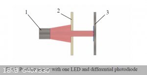
Commercial position sensors which are used in balances
with EFC are mainly operating with one IR-LED and one
differential photodiode.
An IR-LED (1)
illuminates adifferential photodiode (3)
via a narrow movable rectangularaperture (2),
see figure 1.
The difference of the two signals
of the differential photodiode is directly proportional to the
position of the aperture.
A disadvantage of this arrangement is the fabrication of
the narrow rectangular aperture and the large resulting
blockage of the light. Furthermore this requires an
appropriately high current of the LED. Besides this
differential photodiodes are comparatively expensive.
Attachment: an-position-sensing-photodiodes.pdf (322kB)
This file has been downloaded 246 times
[Edited on 19-11-2020 by yobbo II]
|
|
|
yobbo II
National Hazard
Posts: 709
Registered: 28-3-2016
Member Is Offline
Mood: No Mood
|
|
I am beginning to think it is not feasable to build a power supply that will supply a current from 1 to 5mA and be accurate to the nearest 5nA.
As alluded to above.
Looking the attached it appears that the way these are worked is that a chopped supply is fed to the compensation element (force coil) and the
frequency is counted?
Yob
|
|
|
unionised
International Hazard
Posts: 5102
Registered: 1-11-2003
Location: UK
Member Is Offline
Mood: No Mood
|
|
"Looking the attached it appears that the way these are worked is that a chopped supply is fed to the compensation element (force coil) and the
frequency is counted?"
I doubt it.
I think that's a diagram of one of these
https://en.wikipedia.org/wiki/Integrating_ADC
I'd not consider making one; I'd buy it.
|
|
|
unionised
International Hazard
Posts: 5102
Registered: 1-11-2003
Location: UK
Member Is Offline
Mood: No Mood
|
|
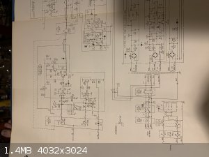
Some while ago... I used to work with a rather old (1975) microbalance which used this principle.
I have the service/instruction manual.
It was only good to 4 1/2 digits; but that isn't bad when it worked down to 2 mg fsd with a resolution of 100 ng.
It has a copy of the circuit diagram which is complicated but not impossible.
I will try to get pictures.
|
|
|
yobbo II
National Hazard
Posts: 709
Registered: 28-3-2016
Member Is Offline
Mood: No Mood
|
|
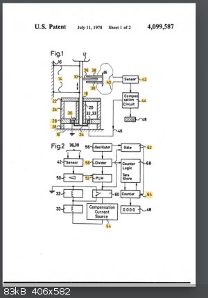
The pat. here definately uses current pulses to 'greatly improve'* the balance.
US US3786678A
.A primary object of the present invention is to provide an improved force-measuring apparatus of the electromagnetic load compensating type, wherein
the load compensating current comprises pulses of uniform amplitude, the lengths of said pulses corresponding with the extent of displacement of the
force responsive movable member from its no-load position. Measuring means are provided for indicating the magnitude of the force to be measured, said
measuring means including oscillator means for supplying high fequency counting pulses, and means for supplying said counting .pulses to a counter
only during periods that correspond with the length of the load compensating current pulses.
I willl put a scope in my balance and see if it is a DC or pulsed going to the coil.
I am convinced that a 0 to 5mA with 5nA resolution power supply would be impossible to build (within reason).
The board of the scales has some sort of oven as there is a polystyrene insulation cup over two unmarked 4 legged components.
*as per usual!
[Edited on 24-11-2020 by yobbo II]
|
|
|
unionised
International Hazard
Posts: 5102
Registered: 1-11-2003
Location: UK
Member Is Offline
Mood: No Mood
|
|
You don't need to build a power supply with that precision.
You use a feedback loop to hold the beam of light in the middle of the two photodiodes.
You put a resistor in series with the coil.
And you measure the voltage across the resistor with a 20 bit (or more) A to D converter.
If you are prepared to put up with a lower resolution, you can just use a voltmeter across the resistor.
If you use a 200 ohm resistor then you turn the problem into measuring 1 volt to a precision of a microvolt.
Difficult- but perfectly possible. A "cop out" solution would be to buy a good voltmeter.
I'm very old-school, so I'd look at something like this
https://www.ti.com/lit/ds/symlink/ads1211.pdf
|
|
|
unionised
International Hazard
Posts: 5102
Registered: 1-11-2003
Location: UK
Member Is Offline
Mood: No Mood
|
|
Let's see if I can get the pictures to upload.
|
|
|
unionised
International Hazard
Posts: 5102
Registered: 1-11-2003
Location: UK
Member Is Offline
Mood: No Mood
|
|
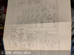
The diagram is a stupid shape; it needed 3 pictures
|
|
|
unionised
International Hazard
Posts: 5102
Registered: 1-11-2003
Location: UK
Member Is Offline
Mood: No Mood
|
|
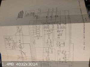
Part 3
|
|
|
| Pages:
1
2 |


