| Pages:
1
2 |
aa1881
Harmless

Posts: 14
Registered: 13-10-2021
Member Is Offline
|
|
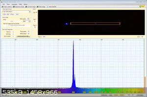
This is a 450 nm laser (having trouble callibrating so ignore the wavelength values)
|
|
|
Sulaiman
International Hazard
Posts: 3558
Registered: 8-2-2015
Location: 3rd rock from the sun
Member Is Offline
|
|
The top image shows some of your challenges,
. not a clear/sharp/focused image of the slit
. haze/bloom around the image (often caused by surface contamination, eg condensation.vs.telescopes)
. strange artefact that I do not recognise down to right of the main image.
(could be lens internal reflections, and is the grating flat?)
Hopefully someone with optics experience can diagnose better?
CAUTION : Hobby Chemist, not Professional or even Amateur
|
|
|
Twospoons
International Hazard
Posts: 1282
Registered: 26-7-2004
Location: Middle Earth
Member Is Offline
Mood: A trace of hope...
|
|
I would not expect to see that little secondary peak coming from a laser. If you change the angle of the grating does the spacing of those two peaks
change?
Helicopter: "helico" -> spiral, "pter" -> with wings
|
|
|
Sulaiman
International Hazard
Posts: 3558
Registered: 8-2-2015
Location: 3rd rock from the sun
Member Is Offline
|
|
The second peak seems to be due to the optical abberation artefact down and right of the main image,
not from the laser.
CAUTION : Hobby Chemist, not Professional or even Amateur
|
|
|
aa1881
Harmless
Posts: 14
Registered: 13-10-2021
Member Is Offline
|
|
The abberations might be from imperfections in the grating, I cleaned it with some isopropyl alcohol to make sure it wasn't dirty but it didn't seem
to help. The focus seems good when remove the lid and focus in the slit. I am now designing a new box for a setup with a reflective grating (a broken
CD). I'll post it when I get it all set up.
|
|
|
aa1881
Harmless
Posts: 14
Registered: 13-10-2021
Member Is Offline
|
|
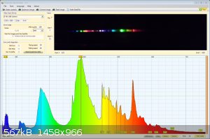
After much trial and error I finally have a setup with clear spectal lines. My only problem now is that the first and second diffraction order are
overlapping. Is this something I can resolve?
Once I'm fully satisfied with the setup I'l post a link to the CAD files for my spectrometer for those interested.
Attached is an image of the spectrum of a CFL for reference.
|
|
|
aa1881
Harmless
Posts: 14
Registered: 13-10-2021
Member Is Offline
|
|
I increased the angle between the light entrance and camera a bit and it has helped somewhat. I am now waiting on a new lens to be able too zoom more
onto the spectrum, so that I can use the primary diffraction instead of the secondary, which overlaps with the tertiary.
I uploaded the files to Thingiverse for those interested:
https://www.thingiverse.com/thing:6573462
|
|
|
Twospoons
International Hazard
Posts: 1282
Registered: 26-7-2004
Location: Middle Earth
Member Is Offline
Mood: A trace of hope...
|
|
Quote: Originally posted by aa1881  | | My only problem now is that the first and second diffraction order are overlapping. Is this something I can resolve? |
Pretty sure this is a fundamental limitation of diffraction gratings, and a good reason to use a prism instead if you want a really wide-band
spectrometer.
The only way around this is to add wavelength filters to the camera sensor eg if the 2nd order red/IR is overlapping the first order UV/blue you
could add a short pass filter over that part of the sensor (blocking red and passing blue)
[Edited on 11-4-2024 by Twospoons]
Helicopter: "helico" -> spiral, "pter" -> with wings
|
|
|
Ubya
International Hazard
Posts: 1232
Registered: 23-11-2017
Location: Rome-Italy
Member Is Offline
Mood: I'm a maddo scientisto!!!
|
|
| Quote: Originally posted by aa1881 | After much trial and error I finally have a setup with clear spectal lines. My only problem now is that the first and second diffraction order are
overlapping. Is this something I can resolve?
Once I'm fully satisfied with the setup I'l post a link to the CAD files for my spectrometer for those interested.
Attached is an image of the spectrum of a CFL for reference. |
are you using here the CD?
you can get more angular distance between diffraction orders by increasing the line density of the diffraction grating.
a CD has about 625 lines/mm, if you use instead a diffraction grating with 1000 lines/mm you shouldn't have any issues.
I use a diffraction grating with 1000 lines/mm and I see an overlap only in the first order near IR
https://ibsen.com/resources/calculators/grating-order-calcul...
use this to play around
[Edited on 13-4-2024 by Ubya]
[Edited on 13-4-2024 by Ubya]
---------------------------------------------------------------------
feel free to correct my grammar, or any mistakes i make
---------------------------------------------------------------------
|
|
|
Twospoons
International Hazard
Posts: 1282
Registered: 26-7-2004
Location: Middle Earth
Member Is Offline
Mood: A trace of hope...
|
|
A better explanation (Pictures!), and the solution to order overlap
https://deltaopticalthinfilm.com/products/continuously-varia...
Helicopter: "helico" -> spiral, "pter" -> with wings
|
|
|
Ubya
International Hazard
Posts: 1232
Registered: 23-11-2017
Location: Rome-Italy
Member Is Offline
Mood: I'm a maddo scientisto!!!
|
|
ohh i had no clue something like that actually existed. pretty dope!
---------------------------------------------------------------------
feel free to correct my grammar, or any mistakes i make
---------------------------------------------------------------------
|
|
|
Twospoons
International Hazard
Posts: 1282
Registered: 26-7-2004
Location: Middle Earth
Member Is Offline
Mood: A trace of hope...
|
|
It occurs to me that a second grating oriented 90 degrees to the first grating could be used as an order sorting filter. Imagine the first grating
spreads horizontally: 1st order IR at 900nm would overlap 2nd order 450nm. The second grating would then vertically separate the 900nm 1st order light
from the 450nm 2nd order light. Not sure how the optics would be set up for this - maybe like running two spectrometers in series, with the second
grating where the image plane would be in the first spectrometer, with another lens following to focus onto the sensor. hard to describe in words and
I dont have a good drawing tool handy. In essence: slit - grating - lens - grating - lens - sensor.
There's probably some reason why this doesn't work though.
[Edited on 15-4-2024 by Twospoons]
Helicopter: "helico" -> spiral, "pter" -> with wings
|
|
|
| Pages:
1
2 |


