Kloberth
Harmless

Posts: 29
Registered: 2-6-2023
Member Is Offline
|
|
Neon sign transformer circuit
Well I know its the wrong forum here but every other forum has not respomded to my question so ill try it here.
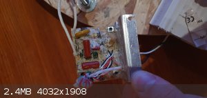
I have a Solid state chinese neon sign transformer and I am trying to remove the ground fault protection from it has anyone experiece with such
transformers or do i need to trace back the circuit?
 
|
|
|
Kloberth
Harmless
Posts: 29
Registered: 2-6-2023
Member Is Offline
|
|
After looking further at the circuit it is a zvs circuit driving a flyback. Just need to figure out what on this is responsible for ground fault
protection
[Edited on 29-3-2024 by Kloberth]
|
|
|
Rainwater
National Hazard
Posts: 800
Registered: 22-12-2021
Member Is Offline
Mood: indisposition to activity
|
|
I would advise against running the circuit without the potting material, at those voltages arcs can form within 1/2in(14mm) or more
To help, we will need a schematic or netlist. There are many different topologies that can produce ground fault detection.
For that small of a driver, im betting on a dual "current mirror" acting as a different pair. Anytime the dif pair is not zero, you have a ground fault.
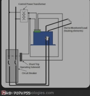
Another common but less accurate method is to wind a untapped transformer to your output.
By winding both output leads together in opposite directions, their currents cancel out. The secondary only produces a current under unbalanced load
conditions
"You can't do that" - challenge accepted
|
|
|


