RNaseH
Harmless

Posts: 1
Registered: 22-4-2019
Member Is Offline
|
|
Revive PE Paragon 1000 FTIR
Hello fellow experimenters,
recently I got my hands on a Perkin Elmer Paragon 1000 FTIR spectrometer in largely useable condition. Switching it on and putting in the reference
polystyrene sample resulted in an immidiate spectrum that closely resembled literature, some minor deviations excluded.
Of course, luck comes to an end, and after it sat for some days (in a dry room), switching it on resulted in an error "erratic laser values" and no
more spectra.
Well, idiotic me quickly googled, got something about slight laser misadjustment in the comparably built FTIR 1600, and of course, I got to work
screwing around with the laser alignment, instead of researching more and using the auto gain feature which would probably have solved the issue right
away.
Now, a few days later, I gained some insight into the device, scored a (mostly useless) manual which was surprisingly hard to come by, and having
fucked up the alignment beyond self-repair.
Today, after inspecting the salt windows and beamsplitter, finding them pretty corroded, I polished them back to translucency using my limited means
(optic wipes as "abrasive" and varying mixtures of water (to get rid of crusts), methanol and acetone. They won't win an award but at least now the
laser dot is pretty much a dot again.
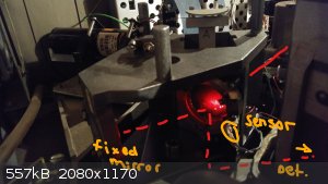
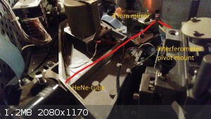
Alas, my question of adjustment. The HeNe-Laser is apparently reflected by an very small mirror (~3 mm) on the optical bench. It is then directed into
the interferometer and onto the beam-splitter, which has a reflective (aluminium?) part with a clear smaller window.
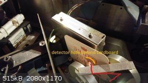
It is my understanding that the coated part is for the IR, and the clear window is for the laser. Behind the window, there is a sensor for the laser,
which gives a reading in the laser-gain adjusting menu. So far, all I do leads the sensor to do nothing, the intensity at maximum gain is somewhere at
0.35 (which is the lowest value, covering the sensor doesn't reduce this value).
And here is where I need help. By screwing around (immensely dumb, I know) I misaligned laser and mirror to a point where I cant fine tune it to
maximum gain value, I first need to know where the laser even needs to go.
By aiming it into the window, I can get a beam into one fixed mirror, get a beam through the parabolic mirrors all the way to the IR detector, but
dont get any increase in signal. Also, the reflection on the splitter aims the laser to the arm of the periscopic mirror.
If I want to get the laser into the periscopic mirror, it invariably goes onto the coated part which leads to almost no light for the fixed mirror and
no more visible dot for the detector.
So, I'm clueless here. Do I really aim for the window? Is there some magic angle that will allow the laser to shine directly onto the sensor? Or is
there some reflection I, so far, "skip" which will make all good again?
Alternatively, considering my repair of the salt materials isn't perfect (but I know it worked even pre-polish) there might be some issue, or the
laser sensor in the interferometer is broken (it seems to react to daylight and a flashlight, but im not perfectly sure of the value range here), or
the board is broken (but self test shows no issue).
Any help to get this godsent tool working again is greatly appreciated.
|
|
|
ftirinih
Harmless
Posts: 27
Registered: 28-10-2007
Member Is Offline
Mood: No Mood
|
|
Congratulations, you are one of a very few hobbyists who get inside an FTIR. It is hard going because there are generally no 'user serviceable parts'
inside. I don't own a Perkin Elmer FTIR, but have Bomem and Nicolet FTIRs.
There is a book that describes FTIRs in great detail, "Fourier Transform Infrared Spectrometry" by Peter Griffiths. On page 119-20 it talks briefly
about the Perkin Elmer design. Figure 5.20 shows how the interferometer works. The two mirrors in your last picture are the moving parts.
Did you remove the beamsplitter to polish the substrates? Did you adjust any of the mirrors? If you did, then the alignment of the interferometer
has been lost. It can be recovered, but I don't know how to do it for your instrument.
Look on YouTube and view videos about Michelson interferometers and they show how to align that type of interferometer, which is similar to what you
have. Its a two beam interferometer.
I wonder if someone who worked at Perkin Elmer in the past could help you.
|
|
|
|


