Trifluoroacetic
Hazard to Others

Posts: 128
Registered: 6-8-2008
Member Is Offline
Mood: No Mood
|
|
DC Power supply
Hi,
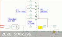
I built a large DC power supply around a large 120v in/50v out transformer. The transformer puts out 10-25 amps. I have rectified the 50v AC and
turned it into DC. I placed 4(4,000MFD capacitors in parallel) and a large constant current regulator that contains an LM317HV regulator with a max
input of 60vdc. The regulator has 12 TIP2955 pass transistors mounted on it to pass high currents.
My question is that when a load is applied I get about 50volts at the capacitors and about 0-45volts out at the regulator which is what I expected
to get but; when the load is not attatched to it I get 70vDC at the filter capacitors and 0-28.8 vdc out from the regulator board. Why does this
happen and how can I prevent it. I'm afraid that the 70volts that are present when no load is attatched could damage the voltage regulator and destroy
the board.
My goal is to use this to supply power to large electromagnets once the supply is re-wired for 220vAC by wiring two transformers primaries in series
and the secondaries in parrallell for increased current.
I have posted a copy of the schematic before it was modified for an LM317HV regulator. The only changes are a 5k potentiometer for voltage control on
the regulator and transient capacitors at the chip terminals.
|
|
|
woelen
Super Administrator
Posts: 7977
Registered: 20-8-2005
Location: Netherlands
Member Is Offline
Mood: interested
|
|
I think that the transformer is somewhat too high rated and the filter capacitors are too low rated. If you use a 50 V AC output, then the DC output
at no load is sqrt(2)*50, which is a little over 70 V DC. The rectifier strips off appr. 1.2 volts, so indeed that you get 70 V DC across the
capacitors is what I expected.
Now suppose there is a load of 15 A (somewhere halfway your rated load). You have 16000 uF capacity. At 15 A current, there is a voltage drop of
15/(16000*1e-6) volts per second, which is 900 volts per second, or 9 V per cycle (100 Hz). Recharging of the capacitors only can be done when the AC
voltage is at the peaks of its amplitude. So, recharging can only be done for a small amount of time. I think that 20 volts drop at the capacitors is
realistic and there will a large ripple of almost 10 V at high load. This is too much. You need a bigger capacitor.
What happens if you slowly increase the load? Start with the unloaded circuit and increase the load from 1 A to 10 A and measure voltage output.
Could you also provide the schematic with the LM317HV? How did you connect the 5 K pot? And what resistor is accross the 1.2 V reference of the
LM317HV?
|
|
|
not_important
International Hazard
Posts: 3873
Registered: 21-7-2006
Member Is Offline
Mood: No Mood
|
|
http://www.national.com/ds/LM/LM117HV.pdf
|
|
|
Trifluoroacetic
Hazard to Others
Posts: 128
Registered: 6-8-2008
Member Is Offline
Mood: No Mood
|
|
Quote: Originally posted by woelen  | I think that the transformer is somewhat too high rated and the filter capacitors are too low rated. If you use a 50 V AC output, then the DC output
at no load is sqrt(2)*50, which is a little over 70 V DC. The rectifier strips off appr. 1.2 volts, so indeed that you get 70 V DC across the
capacitors is what I expected.
Now suppose there is a load of 15 A (somewhere halfway your rated load). You have 16000 uF capacity. At 15 A current, there is a voltage drop of
15/(16000*1e-6) volts per second, which is 900 volts per second, or 9 V per cycle (100 Hz). Recharging of the capacitors only can be done when the AC
voltage is at the peaks of its amplitude. So, recharging can only be done for a small amount of time. I think that 20 volts drop at the capacitors is
realistic and there will a large ripple of almost 10 V at high load. This is too much. You need a bigger capacitor.
What happens if you slowly increase the load? Start with the unloaded circuit and increase the load from 1 A to 10 A and measure voltage output.
Could you also provide the schematic with the LM317HV? How did you connect the 5 K pot? And what resistor is accross the 1.2 V reference of the
LM317HV? |
Thanks Woelen
I only had four 4,000 MFD capacitors on hand when I built this thing but I plan on replacing them. Should i go with a couple 40,000 MFD capacitors
in parrallel? How would I calculate the needed capacitance values?
I just got a 50 AMP meter and shunt so I will be able to measure the actual current output today.
I'm using a factory recomended 240 ohm resistor that is attatched at the regulators output and it's voltage adjust pin. A 5K potentiometer is then
attached to the voltage adjust pin and the ground (negative side of the supply).
I'll post an updated schematic sometime today.
|
|
|
Trifluoroacetic
Hazard to Others
Posts: 128
Registered: 6-8-2008
Member Is Offline
Mood: No Mood
|
|
So even after I replace the capacitors with a larger bank I assume I will still get 70v at th capacitors with no load. Is there any way this voltage
could be clamped to 50v dc?
|
|
|
merrlin
Hazard to Others
Posts: 110
Registered: 3-4-2009
Member Is Offline
Mood: No Mood
|
|
| Quote: Originally posted by Trifluoroacetic | | So even after I replace the capacitors with a larger bank I assume I will still get 70v at th capacitors with no load. Is there any way this voltage
could be clamped to 50v dc? |
You will be forced to dump current any time the rectifier input AC waveform exceeds 50 volts (plus diode drop). Diode clamping in effect adds a
periodic load. If you have a large operating voltage drop across the regulator and transistors, you might consider using a variac in front of your
transformer. Although I've never used SCRs, they might work.
|
|
|
woelen
Super Administrator
Posts: 7977
Registered: 20-8-2005
Location: Netherlands
Member Is Offline
Mood: interested
|
|
| Quote: Originally posted by Trifluoroacetic | | So even after I replace the capacitors with a larger bank I assume I will still get 70v at th capacitors with no load. Is there any way this voltage
could be clamped to 50v dc? |
Yes, replacing the capacitor bank by a larger one only solves the problem of excessive ripple. You can follow merrlin's advice, another option is to
take a series of high-current power diodes and put this in series with the transformer. Each diode will 'consume' appr. 0.6 volts. The advantage of
that solution is price (it is much cheaper), but the disadvantage is that the entire power cycle is shifted downwards and a smaller portion of the
recified sine wave is used for recharging the capacitor bank.
You also could assure that the output of the LM317HV does not go below 22 V. Look at the schematic. None of the terminals of the LM317HV is directly
connected to GND. So, at 70 V input, the LM317HV never sees more than 48 V across any pair of its terminals. Only the difference between the voltage
at the terminals counts. With suitable resistors, you even could get a 100 V regulated output from an LM317!
You also can combine things, like a few power diodes between the capacitor bank and the LM317 and assuring that output voltage does not drop below 20
V.
|
|
|
JohnWW
International Hazard
Posts: 2849
Registered: 27-7-2004
Location: New Zealand
Member Is Offline
Mood: No Mood
|
|
That reminds me - I have several large-capacity condensers on hand, which I bought as a boxed lot with some other things at an auction. I am going to
use some of them in designing an emergency offline power storage and supply system, but I may have some surplus to my requirements and available for
sale. If anyone is interested, please let me know.
|
|
|
Trifluoroacetic
Hazard to Others
Posts: 128
Registered: 6-8-2008
Member Is Offline
Mood: No Mood
|
|
Really? I didn't realize this would be capable of regulating about a 100v in this configuration. That's cool. I just might make an attempt to purchase
a much larger transformer with a higher current and voltage output. I might have to replace my air cooled heat sink with a water cooled heat sink
though.
| Quote: Originally posted by woelen | | Quote: Originally posted by Trifluoroacetic | | So even after I replace the capacitors with a larger bank I assume I will still get 70v at th capacitors with no load. Is there any way this voltage
could be clamped to 50v dc? |
Yes, replacing the capacitor bank by a larger one only solves the problem of excessive ripple. You can follow merrlin's advice, another option is to
take a series of high-current power diodes and put this in series with the transformer. Each diode will 'consume' appr. 0.6 volts. The advantage of
that solution is price (it is much cheaper), but the disadvantage is that the entire power cycle is shifted downwards and a smaller portion of the
recified sine wave is used for recharging the capacitor bank.
You also could assure that the output of the LM317HV does not go below 22 V. Look at the schematic. None of the terminals of the LM317HV is directly
connected to GND. So, at 70 V input, the LM317HV never sees more than 48 V across any pair of its terminals. Only the difference between the voltage
at the terminals counts. With suitable resistors, you even could get a 100 V regulated output from an LM317!
You also can combine things, like a few power diodes between the capacitor bank and the LM317 and assuring that output voltage does not drop below 20
V. |
|
|
|
Trifluoroacetic
Hazard to Others
Posts: 128
Registered: 6-8-2008
Member Is Offline
Mood: No Mood
|
|
Here's a picture of the regulator board in case anyone has an interest in seeing it. All of the 12 pass transistors are located on the back side and
directly mounted to the heat sink which makes up the high current connection for the collectors of the transistors.
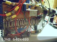
[Edited on 15-6-2009 by Trifluoroacetic]
|
|
|
Trifluoroacetic
Hazard to Others
Posts: 128
Registered: 6-8-2008
Member Is Offline
Mood: No Mood
|
|
Just out of curiosity what would happen if the output dropped below 22 volts and how do you calculate the max voltage seen across the regulator pins?
Thanks.
| Quote: Originally posted by woelen | | Quote: Originally posted by Trifluoroacetic | | So even after I replace the capacitors with a larger bank I assume I will still get 70v at th capacitors with no load. Is there any way this voltage
could be clamped to 50v dc? |
Yes, replacing the capacitor bank by a larger one only solves the problem of excessive ripple. You can follow merrlin's advice, another option is to
take a series of high-current power diodes and put this in series with the transformer. Each diode will 'consume' appr. 0.6 volts. The advantage of
that solution is price (it is much cheaper), but the disadvantage is that the entire power cycle is shifted downwards and a smaller portion of the
recified sine wave is used for recharging the capacitor bank.
You also could assure that the output of the LM317HV does not go below 22 V. Look at the schematic. None of the terminals of the LM317HV is directly
connected to GND. So, at 70 V input, the LM317HV never sees more than 48 V across any pair of its terminals. Only the difference between the voltage
at the terminals counts. With suitable resistors, you even could get a 100 V regulated output from an LM317!
You also can combine things, like a few power diodes between the capacitor bank and the LM317 and assuring that output voltage does not drop below 20
V. |
|
|
|
woelen
Super Administrator
Posts: 7977
Registered: 20-8-2005
Location: Netherlands
Member Is Offline
Mood: interested
|
|
The LM317 has 1.2 ... 1.25 volts across the output pin and the regulator pin. This chip does its best to keep the voltage across these two pins
constant. If you place a resistor R between these pins and a resistor nR between the regulator pin and ground, then the output voltage (assuming the
regulator pin does not draw nor supply any current) must be (n+1)R. The input voltage is the voltage across the capacitor bank.
So, based on this you must be able to compute the voltage different between any of the terminals. You must assure that the voltage across any two pair
of terminals must remain below 48 V. If it goes above this value then the component may say POOF  Most likely there is a certain tolerance and most actual LM317's can withstand somewhat more than 48 V, but the
manufacturer of the chips guarantees correct operation up to 48 V. Be sure not to sit on the edge, it makes your board less reliable. Most likely there is a certain tolerance and most actual LM317's can withstand somewhat more than 48 V, but the
manufacturer of the chips guarantees correct operation up to 48 V. Be sure not to sit on the edge, it makes your board less reliable.
If e.g. you want 100 V regulated output, then you could take a capacitor bank which has 125 V across it, take R = 250 Ohm and take nR = 20 kOhm +
5KOhm pot for fine adjustment to adjust to exactly 100 V. If you do such a thing, then always assure that you cannot adjust the output voltage to such
a low value that it drops below e.g. 80 V, otherwise again your LM317 may go POOF. With the values described above, however, this cannot occur.
[Edited on 15-6-09 by woelen]
|
|
|
Trifluoroacetic
Hazard to Others
Posts: 128
Registered: 6-8-2008
Member Is Offline
Mood: No Mood
|
|
Thankyou for the info.
I just might make an attempt to build a board that can regulate 100v but at an extremely high current using pass transistors like I've done with this
one.
| Quote: Originally posted by woelen | The LM317 has 1.2 ... 1.25 volts across the output pin and the regulator pin. This chip does its best to keep the voltage across these two pins
constant. If you place a resistor R between these pins and a resistor nR between the regulator pin and ground, then the output voltage (assuming the
regulator pin does not draw nor supply any current) must be (n+1)R. The input voltage is the voltage across the capacitor bank.
So, based on this you must be able to compute the voltage different between any of the terminals. You must assure that the voltage across any two pair
of terminals must remain below 48 V. If it goes above this value then the component may say POOF Most likely there is a certain tolerance and most actual LM317's can withstand somewhat more than 48 V, but the
manufacturer of the chips guarantees correct operation up to 48 V. Be sure not to sit on the edge, it makes your board less reliable.
If e.g. you want 100 V regulated output, then you could take a capacitor bank which has 125 V across it, take R = 250 Ohm and take nR = 20 kOhm +
5KOhm pot for fine adjustment to adjust to exactly 100 V. If you do such a thing, then always assure that you cannot adjust the output voltage to such
a low value that it drops below e.g. 80 V, otherwise again your LM317 may go POOF. With the values described above, however, this cannot occur.
[Edited on 15-6-09 by woelen] |
|
|
|
Trifluoroacetic
Hazard to Others
Posts: 128
Registered: 6-8-2008
Member Is Offline
Mood: No Mood
|
|
Hi folks I just installed two 100,000 MFD capacitors at 100VDC in series to filter the DC ripple out of this unit. I also installed a new transformer
that puts out 35 volts DC at 40 amps. I installed two sets of (4) 200v capacitors at 2900MFD in a voltage doubling configuration. The output at the
voltage doubler should be at 70vDC. That voltage will be fed into the two 100,000MFD capacitors.
My question is do you feel that this will provide enough capacitance?
Will the output current be reduced by the voltage multiplier circuit. If so by how much and how do you determine what the current drop is? I'm
thinking the voltage multiplier capacitors should have voltage equalizing/ bleeding resistors. What ratings would you recomend I use. The same goes
for the two 100,000MFD caps.

|
|
|


