bearbot22
Harmless

Posts: 16
Registered: 10-4-2018
Member Is Offline
Mood: No Mood
|
|
DIY Divided electrochemical cell with stirring and cooling
I'm proud to present the design of an Electro-Chemical cell that has been developed and improved over a long period of time, with the aim of
developing a DIY electrolysis cell that is reliable, features membrane aka diaphragm, stirrer and cooling but also is made from inexpensive and
readily available parts.
Blueprint with parts list of the cell can be found in the attached file.
Wondering what to make with such a cell? Well - a lot of chemicals. Take a look in sciencemadness' Library: The Manufacture of Chemicals by Electrolysis
What follows now is a rather long "making of"- text with some hopefully useful information for anyone who wants to design or improve an electrolysis
cell.
I started with a beaker-type cell because i had a beaker in my collection. On top of the beaker I put a plastic lid into which I drilled slots and
holes for electrodes.
On the Internet i found a tutorial for a DIY magnetic stirrer made from an old PC: Magnets taken from a HDD glued to a CPU fan and connected to the PC
power supply, and a sandwich box as enclosure. This magnetic stirrer worked really well and for a long time and the PC's power supply also provided 5V
and 12V DC for electrolysis. Of course, I still needed a magnetic bar for the stirrer. I made some out of screws and nuts, wrapped with tape or shrink
tubing or plastic tubes with magnets in them. But because they didn't last and weren't balanced well, I quickly opted for PTFE magnetic stirring bars.
To measure the current, I got a cheap digital multimeter from the hardware store.
Next i went for an an more flexible power supply, which I built from the transformer of an IKEA halogen lamp and an electronic adjustable AC/DC
module. So I was able to adjust voltage and read the flowing current on the multimeter.
Membrane aka diaphragm was a tricky part. I tried many things: Sheep casings and gelatine ... they decomposed. A salt bridge hadn't allowed enough
current to flow.
Gore-Tex, composable plastic film and Fimo haven't allowed electricity to pass at all, nor have porcelain vessels with scraped glaze, unglazed
porcelain or most commercially available flower pots.
AFAIK Ceramics are fired twice to make em firm an waterproof. Suitable as a membranes, are ceramics that are fired only once such as Terracotta or
Blumat water dispensers for flowers. But their thick walls allow only little current to flow.
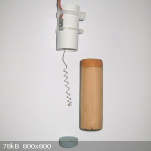
The clay tubes i found are sold in aquarium shops in stacks of six as breeding shelter for shrimp. You 'll need to scrape the tubes off the stack and
also have to grind the glazing off in- and outside. This can be done with a rough round file and a sharp screwdriver.
Similar caves are also offered with a closed bottom, but I haven't found a way to remove the inner glaze without breaking it.
If someone has the opportunity to build a test tube-shape porous ceramics that is fired only once, that would certainly be a pretty cool improvement.
Using the shrimp clay tube i needed to seal the bottom, which is not as easy as i assumed. Stuck a plastic shopping cart chip to it but no glue I know
kept it. So I tried tape, stoppers, etc... nothing lasted. Even a long screw made out of nylon which i stuck through the tube to hold the bottom
decomposed. It seems that during electrolysis, the inside of an anode cell turns into a corrosive hell. That's why I came up with a bracket of cable
ties.
The level of anode electrolyte should be higher than the electrolyte level in the cell. I think this way osmotic pressure prevents redox reactions.
As a supposed further improvement, I bought an quite expensive fuel cell membrane. Building an anode cell for this membrane was complex because seals
were needed and had to hold together with a lot of screws. This finally worked but did not allow more current to flow than the clay tube did. After
the first electrolysis the (dry) membrane broke mechanically. So I decided to stick to the clay tube.
Nafion? I didn't test this. IMHO it's too expensive and difficult to obtain for a DIY cell.
For cooling, I had a double-walled vessel in mind from the beginning. First I put the beaker in a plastic cup to which I hot-glued tubes for inlet and
return. I put a pot with diluted antifreeze and a small pump in a freezer (drilled holes in the Cover for tubing and power supply).
Since the beaker could move inside the cup, the stirring bar smeared off quickly or if the inlet or outlet were not properly free, it cooled too
little or flooded the beaker so this was not particularly reliable.
Using a cylindrical 'Lock-n-Lock' container, I was able to built a much more reliable double-walled vessel. Cut a suitable hole in the plastic lid,
place the beaker in it and fixed it waterproof with hot glue.
When electrolysis ran for several hours or even days, a lot of condensation water formed and finally the magnetic stirrer stood in a puddle. So I put
the beaker and magnetic stirrer rihgt inside the freezer. This turned out to be a good idea and I did a lot of electrolysis successfull with this
setup.
Since there already were holes in the freezer's cover, any hydrogen gas could escape.
Temperature control was done by adjusting the freezer, which was not very accurate. So I ordered a cheap 'STC1000' controller on the Internet. With
this, i had the pump and freezer run only when cooling was needed.
However, the handling of the cell was still a bit fiddly, firstly because the plate with the electrical connections wasn't really fixed to the beaker
and secondly the Lock'n'Lock vessel could slip on the magnetic stirrer and thus cause the stirrer to fail.
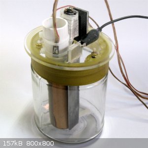
That's why I redesigned an electrolytic cell with everything fastened to a screw-on cap. For this I replaced the beaker with a cylindrical glass jar
with a screw cap made of plastic and found a suitable one in a local shop with 500g of honey in it. This is the reason why I call the cell's design
"Honeypot".
Maybe Honey is sold in these jars only where i live so you might look for a cylindrical glass jar with plastic screw cap filled with peanut-butter,
marshmallow spread or whatever.
Cut out the lid and screwed on a sturdy disc made of acrylic glass to which stirring-motor, cathode, anode-cell and temperature sensor are attached.
The attached drawing shows how its done exactly.
As a stirring drive, I initially used a cheap DIY Robotics motor with plastic gearbox, but unfortunately those fail after a few hours of continuous
operation. A 20D 6V DC motor with metal gearbox plus a USB power supply seems to be much better.
As a power supply for electrolysis, I replaced the IKEA-Transformator+Multimeter- Thing with an adjustable lab power supply (2A/30W) because its
short-circuit-proof and less wiring is needed.
For cooling I use a fridge with icebox. I unscrew the top cover and cut a circular hole in the insulation so i can put the cell right inside the
icebox. After reassembling, this modification of the Fridge is barely visible. During electrolysis, Fridge is set to max cooling and powered via the
STC-1000 controller. A soft cooling pad under the glass jar improves heat dissipation.
Hope this gets your lab a little further - BearBot22
Attachment: honeypot3.pdf (75kB)
This file has been downloaded 401 times
|
|
|
mysteriusbhoice
Hazard to Others
Posts: 476
Registered: 27-1-2016
Member Is Offline
Mood: Became chemistry catboy Vtuber Nyaa
|
|
use ionomer cement if you want a cheap good membrane
cement and cation/anion exchange resin commonly sold in water filter store cement to ionomer cement wt ratio 1:3
you can also use plaster of paris if instead of cation exchange resin.
this mixture is mixed with water and casted across a glass container with 2 dividing walls which will produce a dam (membrane) which is highly
conductive due to the imbedded ion exchange resin or plaster of paris CaSO4 which can also exchange ions.
|
|
|
bearbot22
Harmless
Posts: 16
Registered: 10-4-2018
Member Is Offline
Mood: No Mood
|
|
hi mysteriusbhoice,
the electrolyte used is 7-10% H2SO4 in water/alcohol - i'm not really sure plaster of paris aka gipsum will last.
also i read cement becomes instable when in contact with gipsum before it is totally dry.
i've never heard of ionomer cement before, so i'll give this a try.
|
|
|
mysteriusbhoice
Hazard to Others
Posts: 476
Registered: 27-1-2016
Member Is Offline
Mood: Became chemistry catboy Vtuber Nyaa
|
|
Quote: Originally posted by bearbot22  | hi mysteriusbhoice,
the electrolyte used is 7-10% H2SO4 in water/alcohol - i'm not really sure plaster of paris aka gipsum will last.
also i read cement becomes instable when in contact with gipsum before it is totally dry.
i've never heard of ionomer cement before, so i'll give this a try.
|
Gypsum will last with H2SO4 as I've used it in up to 20% without issues but it will be attacked by NaOH.
Also the gypsum and cement being unstable only matters for construction applications and this membrane won't bear any load and they seem rock solid.
Anyway cation exchange resin with cement is good too and use glass container not plastic because plastic will flex.
|
|
|
mysteriusbhoice
Hazard to Others
Posts: 476
Registered: 27-1-2016
Member Is Offline
Mood: Became chemistry catboy Vtuber Nyaa
|
|
I have a video on my channel about making various ion exchange membranes and the ionomer cement is convenient and allows for a membrane which is both
not as porous but highly conductive to the particular ions of choice depending on the resin you choose.
The current flow is shown in my video and it's quite decent compared to terracotta which only really did decent past 12 volts.
|
|
|
sykronizer
Harmless
Posts: 14
Registered: 16-12-2017
Member Is Offline
Mood: omnivorous
|
|
the membrane is not that hard, just use the plastic separator found inside any lithium ion battery, they conduct great just make sure to not let the
temp get too high otherwise the micropores will close up, less than 50 Celsius is fine.
|
|
|
Hexabromobenzene
Hazard to Self
Posts: 99
Registered: 27-4-2021
Member Is Offline
|
|
I know about separator from li-ion battery, but separator with enough size is rare. Plastic bag is common. They made from polyethylene. Can thin bag
use for electrolysis?
|
|
|
Sulaiman
International Hazard
Posts: 3561
Registered: 8-2-2015
Location: 3rd rock from the sun
Member Is Offline
|
|
I've not tried polyethylene as a membrane because I would be surprised if it works.
I've always considered polyethylene to be an impermeable electrical insulator
PS regarding pots etc. :
they have to be porous enough to allow the pores to fill with electrolyte because dry ceramics are insulators.
If very porous then too much electrolyte mixing occurs
If very fine pores then a long soak is required for the electrolyte(s) to penetrate
(the porous pots that I have add about 1 Ohm to 1M sulphuric acid or copper sulphate solutions)
Cleaning them between uses of different electrolyte can be very difficult
Metallic ions 'plating out' within the bulk of the membrane/pot can be a problem also
There are many reasons why porous pots are rarely used.
But I do like the resemblance to (or imitation of) early batteries.
[Edited on 3-3-2023 by Sulaiman]
CAUTION : Hobby Chemist, not Professional or even Amateur
|
|
|
Hexabromobenzene
Hazard to Self
Posts: 99
Registered: 27-4-2021
Member Is Offline
|
|
You're right. Untreated polyethylene will be an insulator. Here, a method was proposed for making a diaphragm by impregnating a fibrous material with
a polymer solution and dipping it in water. This forms a porous polymer. This can be done with polystyrene and PVC
Probably latex. It is porous in itself due to manufacturing technology. But I have no data on its chemical stability. Is it resistant to 20% alkali or
30% sulfuric acid with chlorine and oxidants sometimes? Polystyrene is resistant to all these conditions
In this case, balloons and condoms can be used as a diaphragm.
But if we do experiments with organic substances, then such a diaphragm can be destroyed. The only option for organic electrochemistry is ceramics and
porous polypropylene from batteries
|
|
|
bearbot22
Harmless
Posts: 16
Registered: 10-4-2018
Member Is Offline
Mood: No Mood
|
|
Improved DIY Electrolytic Cell
I improved the cell-design. Honeypot is now a lot easier to build and to handle.
Whith a current of up to 1,5 Amperes at 8,8 Volts various electrochemical organic syntheses are possible using Honeypot, e.g. reduction of
nitroalkenes to the according oximes and amines.
Diaphragm chamber
Hope you like. Here are complete instructions including cooling and stirring:
Attachment: HONEYPOT_IMPROVED.pdf (150kB)
This file has been downloaded 211 times
|
|
|
mysteriusbhoice
Hazard to Others
Posts: 476
Registered: 27-1-2016
Member Is Offline
Mood: Became chemistry catboy Vtuber Nyaa
|
|
if the cylinder was made of ionomer cement I wonder how much higher the current can be pushed thru.
|
|
|
bearbot22
Harmless
Posts: 16
Registered: 10-4-2018
Member Is Offline
Mood: No Mood
|
|
Hi mysteriusbhoice!
| Quote: Originally posted by mysteriusbhoice | use ionomer cement if you want a cheap good membrane
cement and cation/anion exchange resin commonly sold in water filter store cement to ionomer cement wt ratio 1:3
you can also use plaster of paris if instead of cation exchange resin.
this mixture is mixed with water and casted across a glass container with 2 dividing walls which will produce a dam (membrane) which is highly
conductive due to the imbedded ion exchange resin or plaster of paris CaSO4 which can also exchange ions. |
I tried making this kind of membrane weeks ago.
Ordered some ion exchange resin Purolite MB 400 (looks nice, like amber-golden sand).
Mixed it with cement and water in recommended ratios to cast.
But when i retrieved it from the form the result just crumbled.
Tried other ratios also but did not get anything usable.
|
|
|
mysteriusbhoice
Hazard to Others
Posts: 476
Registered: 27-1-2016
Member Is Offline
Mood: Became chemistry catboy Vtuber Nyaa
|
|
cement takes a few days to cure completely I would let it set for a day and put it underwater for 1 week to fully cure.
|
|
|
khlor
Hazard to Self
Posts: 82
Registered: 4-1-2014
Location: Who knows, really...
Member Is Offline
Mood: No Mood
|
|
| Quote: Originally posted by bearbot22 | I improved the cell-design. Honeypot is now a lot easier to build and to handle.
Whith a current of up to 1,5 Amperes at 8,8 Volts various electrochemical organic syntheses are possible using Honeypot, e.g. reduction of
nitroalkenes to the according oximes and amines.
Diaphragm chamber
Hope you like. Here are complete instructions including cooling and stirring:
|
Very interesting project, I’ve been looking ths thread for a while.
Please allow me to give my contribution, hope it can give you a few ideas on improving your own project.
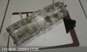
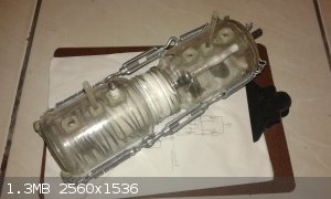
Below there are some pictures of what I can only describe as about 18 months of experimentation and hard work. This one was the latest, never
used(though it is the second and early variations were used to make chlorine with some success) it has been over a year already since I last touched
it before today.
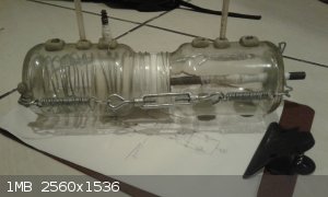
The design consists of two jars with holes drilled with them for gas outlet, electrodes connections and ports for electrode feed and output, both
chambers are divided by a clay/ceramic cup used as diaphragm. I used it successfully for electrodialysis as well.
I’d post the design papers but I would like to avoid having my manuscript on the net, however if you have interest I can make the drawings only.
"NOOOOOO!!! The mixture is all WROOOOOOONG!"
|
|
|
Sulaiman
International Hazard
Posts: 3561
Registered: 8-2-2015
Location: 3rd rock from the sun
Member Is Offline
|
|
Congratulations !
A working finished* product.
very nice work.
* do projects ever really end ?
CAUTION : Hobby Chemist, not Professional or even Amateur
|
|
|
bearbot22
Harmless
Posts: 16
Registered: 10-4-2018
Member Is Offline
Mood: No Mood
|
|
Hi Khlor! Thanks a lot for adding your design here.
| Quote: Originally posted by khlor |
The design consists of two jars with holes drilled with them for gas outlet, electrodes connections and ports for electrode feed and output, both
chambers are divided by a clay/ceramic cup used as diaphragm. I used it successfully for electrodialysis as well.
|
It's a different approach in designing a divided electrochemical cell, but also using household and hardware materials.
That is very inspiring for me to see!
No doubt about this being a lot of hard work - drilling holes in round glass vessels is not a beginner's job. 
I specially like the concept of holding the jars and diaphragm together with springs and turnbuckles so you can adjust pressure.
Do you need additional sealing for the diaphragm?
What material is used for sealing the drilled holes?
Can you tell what current / voltage you could work with?
|
|
|
khlor
Hazard to Self
Posts: 82
Registered: 4-1-2014
Location: Who knows, really...
Member Is Offline
Mood: No Mood
|
|
| Quote: Originally posted by bearbot22 | Hi Khlor! Thanks a lot for adding your design here.
| Quote: Originally posted by khlor |
The design consists of two jars with holes drilled with them for gas outlet, electrodes connections and ports for electrode feed and output, both
chambers are divided by a clay/ceramic cup used as diaphragm. I used it successfully for electrodialysis as well.
|
It's a different approach in designing a divided electrochemical cell, but also using household and hardware materials.
That is very inspiring for me to see!
No doubt about this being a lot of hard work - drilling holes in round glass vessels is not a beginner's job.
I specially like the concept of holding the jars and diaphragm together with springs and turnbuckles so you can adjust pressure.
Do you need additional sealing for the diaphragm?
What material is used for sealing the drilled holes?
Can you tell what current / voltage you could work with? |
Thank you for your words, your praise do me great honor, specially when it comes from someone doing the same thing on a semi professional level. And
yes I do not have access to good tools and materials so I had to use off the shelf parts and a great deal on hard work and imagination to improvise
this.
And the dilling is not as hard as one might imagine but it does take technique and practice to get it right.
It was something that came when I was in the shower, so I bout the turnbuckles and galvanized wire for the springs(yes, hand made springs)
1. Yes, I use PTFE tape(here known as plumbers tape used to seal threaded tubes) to make some sort of O ring to stay in between the mouthsof the jars
and the pressure of the springs keep all in place so it does not leak, I found this design to be the best based on trial and error, so, yes... a lot
of work and angry tears went into this. When working with these things, remember, PTFE is your friend!
2. I used epoxy binary compound. When it cures it looks like some ceramic, it resists well to chlorine and acidc environments, but do not let it in
contact with sodium hydroxide, it will turn it into some weak rubber, I think the composite material used is aluminossilicate and sodium hydroxide
will leach it, plus it loses adherence to the glass.
3. The one in the photos is a revision design built about 18 months ago, never used nor tested so I cannot answer this question honestly but, it is
supped to have better current density based on the original that looks just like what you saw on the photos. With that being said I managed to squeeze
about 1.5A at 5v into this. My main limitation though is electrodes, I use graphite and overtime it exfoliate, but it is cheap to replace which is
good so I put up with it.
Note: my chathode uses galvanizedl wire, not the best material I am gonna change it, I am open to sucgestions. I thought of iron or copper wire.
Edit:
Aditional note, this design is basically the product of my need to collect the gases, in the middle tubes of each jar as you can see, hoses would be
connected to allow for chlorine or whatever gas comes at the anode and hydrogen on the cathode to be collected, true I could make it simpler and not
care about electrolytes but I decided to go all the way and score on the sodium hydroxide I know I can always find a use later. You can later check my
thread on HCl production plant here on technochemistry at the time of the experiments this specific design was the one that allowed to make many grams
of chlorine gas.
Edit2: typos correction
[Edited on 2-9-2023 by khlor]
[Edited on 2-9-2023 by khlor]
"NOOOOOO!!! The mixture is all WROOOOOOONG!"
|
|
|
DXFlatline
Harmless
Posts: 4
Registered: 18-9-2023
Member Is Offline
|
|
Ceramic pots for electrolysis membranes are widely available commercially. The correct term is "porous cup", I bought mine from Amazon.
|
|
|
khlor
Hazard to Self
Posts: 82
Registered: 4-1-2014
Location: Who knows, really...
Member Is Offline
Mood: No Mood
|
|
I wish I knew this way back. Feel so dumb now.
"NOOOOOO!!! The mixture is all WROOOOOOONG!"
|
|
|
DXFlatline
Harmless
Posts: 4
Registered: 18-9-2023
Member Is Offline
|
|
I've started making one based on bearbot's designs:

It's not finished yet needs a stiring paddle and the STG-1000 probe putting in glass. I've got a unique method for cooling but I've not tested it yet
and I need to make a potentiostat circuit.
|
|
|
bearbot22
Harmless
Posts: 16
Registered: 10-4-2018
Member Is Offline
Mood: No Mood
|
|
This looks very nice!
What method of cooling is it?
Potentiostat.. whow!.. this would also require a reference electrode!?
Seems you're up for a more sophisticated cell.
I'd love to hear about your plan, DXFlatline, please keep us updated.
|
|
|
Hexabromobenzene
Hazard to Self
Posts: 99
Registered: 27-4-2021
Member Is Offline
|
|
mysteriusbhoice
I found a new method of manufacturing diaphragm for electrolysis. It looks like your method, but does not needs solvents. This diaphragm is flexible
and chemically resistant. For the manufacture of diaphragm, you will need foam LDPE for packaging. You need to dip it in boiling water. In hot water,
the foam softens and bubbles of gas come out of it forms micro holes. Then the foam WHILE IT HOT is rolled up with a rolling pin to create a denser
structure . You need of thick foam at least 1 cm thick. More thin foam diaphragms noticeably pass water. Thicker LDPE Foam is usually carried out by
welding a few less subtle ones. Look for them. You can also use the LDPE foam for construction
|
|
|
dicyanin
Hazard to Self
Posts: 57
Registered: 29-3-2020
Location: Europe
Member Is Offline
Mood: inquisitive
|
|
Beautiful work  I am tempted to build one according to your design. Is the
resistance across the shrimp breeding tube diaphragm workable? I've used flowerpots succesfully in the past, but resistance is usually high even after
soaking in dilute sulfuric acid, things heat up fast and especially the anode suffers from this. The other downside of flowerpots is their shape &
size and the fact that the setup is open to the atmosphere releasing corrosive vapors. I am tempted to build one according to your design. Is the
resistance across the shrimp breeding tube diaphragm workable? I've used flowerpots succesfully in the past, but resistance is usually high even after
soaking in dilute sulfuric acid, things heat up fast and especially the anode suffers from this. The other downside of flowerpots is their shape &
size and the fact that the setup is open to the atmosphere releasing corrosive vapors.
I have always wondered about Tyvek, which is semipermeable high density polyethylene, it allows for gas/vapour exchange but is waterproof, so I'd assume it would let current pass but not the solvent? Tyvek is said to be quite
resistant against acid and base.
Or perhaps these cylindrical shaped corundum lab crucibles?
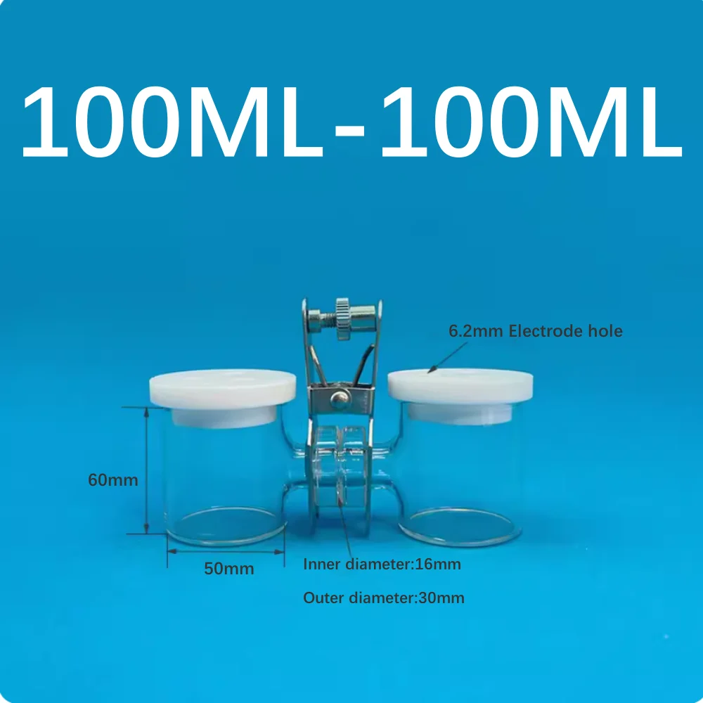
You can buy Nafion perfluorosulfonic acid-PTFE membrane from China but even the cheaper knockoffs are $20 for a 3 x 3 cm size film. I've also seen H-type divided cells for sale but they aren't cheap either, up to $200 for 2x 100ml size with a clamp and Nafion diaphragm included.
To prepare a lead cathode, lead can be finicky regarding surface purity and give inconsistent results. It is best to pre-treat them in a divided cell
with 10% aq. H2SO4 or Na2SO4 electrolyte, use the cathode-to-be as anode (and another piece of lead as
cathode) and run a current through it until it is covered with a thick chocolate-brown layer of lead dioxide. Then switch polarity and run a current
until all oxide is reduced, leaving a gray layer of spongy lead. In this way even roofing sheet grade lead can be used as a reliable high overvoltage
cathode for electroreductions with no other preparation that a light sanding and an acetone rub to clean the surface before pre-treatment.
The only thing I would add to your design, although it is optional, is an extra hole for a reference electrode over the catholyte. I've seen Chinese
calomel and silver-silver chloride reference electrodes sold for about $30 a piece. This allows for fine-tuning the required voltage over the cathode
for a specific reaction, minimizing loss as heat and competing hydrogen evolution.
| Quote: Originally posted by Hexabromobenzene | | I know about separator from li-ion battery, but separator with enough size is rare. Plastic bag is common. They made from polyethylene. Can thin bag
use for electrolysis? |
Back in the day I've used the separator envelopes inside car batteries, which separate the lead electrodes from the lead dioxide wafer electrodes.
They consist of microporous polyethylene, and they work well as diaphragm, but in my experience they tend to be leaky and easily damaged. Also I don't
want to go through the hardship of opening an old car battery again, probably contaminated myself with enough lead for one lifetime during that
ordeal.
I don't think a plastic bag will work. The porous PE separators resemble paper more than plastic bags in how they feel and how easily they tear.
Here's some reading material on the manufacture of microporous battery separators.
[Edited on 4-4-2024 by dicyanin]
sic transit gloria mundi
|
|
|
Hexabromobenzene
Hazard to Self
Posts: 99
Registered: 27-4-2021
Member Is Offline
|
|
See my post above. I made a porous material of LDPE packaging foam. If it works as a diaphragram, it will be a very cheap durable and persistent
material
|
|
|


