yobbo II
National Hazard

Posts: 710
Registered: 28-3-2016
Member Is Offline
Mood: No Mood
|
|
Inductor and capacitor for rectifier output filter
Can anyone point me in the direction of making filter circuits for the output of a 2 or four diode rectifier.
I am having no luck on obtaining information regarding the size of inductor and capacitor required. The inductor needs to be air gapped to deal with
the DC.
I will be using the core of an MOT for the inductor.
The usual advice is that the whole thing will end up being larger and heavier than just simply using a larger transformer at the start but I want to
go the inductor/capacitor(s) route.
Thanks,
Yob
|
|
|
Sulaiman
International Hazard
Posts: 3562
Registered: 8-2-2015
Location: 3rd rock from the sun
Member Is Offline
|
|
Look for PSUD2 by Duncan, windows only I think.
Much easier than a full simulator.
An inductor can really reduce ripple and/or improve efficiency,
best suited to loads that draw a fairly constant current,
remember,
the flyback voltages can be quite high,
when you try to open circuit an inductor that has significant current passing through it,
I've given myself quite a few surprises this way 
PS try C-L-C, eg 1,000uf high ripple - inductor - 10,000uF
Often electrolytic capacitors are sold with a minimum order quantity, eg 5
You can simulate 1cap - inductor - 4caps
Or 2caps - inductor - 3caps etc.
Also, your choice of rectifier can reduce psu heating a lot.
[Edited on 16-2-2024 by Sulaiman]
CAUTION : Hobby Chemist, not Professional or even Amateur
|
|
|
Rainwater
National Hazard
Posts: 800
Registered: 22-12-2021
Member Is Offline
Mood: indisposition to activity
|
|
Depends alot on which type of rectifier you use.
3phase is best, next up is full bridge, and the worst is single diode rectifier.
Basicly your building a low pass filter.
Need a few numbers to provide useful feedback.
| Code: |
Input voltage (ACrms):
Input frequency:
Output voltage DC:
Output current:
Maxium desired ripple:
|
hyperphysics online calculator
[Edited on 16-2-2024 by Rainwater]
"You can't do that" - challenge accepted
|
|
|
semiconductive
Hazard to Others
Posts: 287
Registered: 12-2-2017
Location: Scappoose Oregon, USA.
Member Is Offline
Mood: Explorative
|
|
It usually is larger to have both a transformer and an inductor; because there is wasted space in each. But, a larger transformer doesn't necessarily
cause less ripple in the output; so I'm not sure why people are suggesting a bigger transformer is better.
You're using a two diode rectifier, which is split phase. Therefore, your mains transformer is likely center tapped. You will get pulsing at twice
the frequency of the mains; eg: either 100 or 120 pulses a second for 50 to 60Hz mains.
Sauliman's suggestion of using two capacitors on either side of the inductor is recommended.
There ought to be a capacitor from the center tap of the transformer to both the diodes rectified outputs.
A typical motor winding (MOT?) has a few millihenries of inductance in my experience.
Since you've already chosen the inductor, you should give more information about it since it basically limits what can and can't be done with the
filter circuit.
Do you know the inductance of the motor? Or do you know it's DC resistance, and can you estimate how many winds of copper it has?
Without this information; we'd have to walk you through an experimental way of figuing out what you have; and what you can do with it. I'm not sure
what you are expecting.
Rainwater's questions would be very helpful if you are able to answer them.
|
|
|
Twospoons
International Hazard
Posts: 1282
Registered: 26-7-2004
Location: Middle Earth
Member Is Offline
Mood: A trace of hope...
|
|
Before we can answer your question we need to know how much current you want to supply, and how much voltage ripple is acceptable.
Basic rule of thumb for a full bridge rectifier is to use roughly 1000uF per amp of output current. Use of an inductor is usually not necessary -
there are better ways of producing smooth DC if thats what you need.
Supplying some background info to these questions would be enormously helpful: e.g. what is it you want to power?
Helicopter: "helico" -> spiral, "pter" -> with wings
|
|
|
yobbo II
National Hazard
Posts: 710
Registered: 28-3-2016
Member Is Offline
Mood: No Mood
|
|
Firstly an MOT is a Microwave Oven Transformer!
I will be dismantling the transformer, removing all windings and putting a winding onto the core and gapping the core.
These transformers have a current shunt in them (which will be removed). They are also a gapped core as the E and the I pieces are not interleaved
like you have in a 'more normal' transformer. Found this out when I cut the two weldes that hold on the I lump (all the I's are in one lump, and all
the E's are in another single lump) and seperated the I from the E.
I don't have a detailed specification of a particular power supply that I want to build. I want to know how you would calculate or estimate the
capacitance and inductance needed for this particular type of filter.
I would be using a four diode rectifier. Single phase 50Hz. Output voltage in the region of 5 or six volts DC. The transformer that I intend to use
is another MOT with a output winding wound onto it to supply from a few amps to perhaps 100 amps.
I would probably use two MOT's with the primaries in series on a 240v supply (the mains) as these transformers have a very skimpy number of primary
turns (they run a very high magnetizing current when not connect to a load). This means that you have a center tap sitting there when you wind an
output winding on each transformer so I might use a two diode rectifier (to contradict what I said above!). I would probably have a number of taps on
the secondary's so that I can have different voltages at the output but not that far away from 6 volts DC.
Ripply, I don't really know. As little as possible without breaking the bank on caps. The MOT inductor will not break the bank.
The caps/inductor filter is very simple and rugged (I think).
I have a toroid from a fairly large motor (few horse power single phase) with all the motor windings removed. Perhaps I could try winding some turns
of wire onto it and see what inductance value I get. It is not gapped but is so large it may not saturate?
I went to the PSUD2 by Duncan page but the software does not seem to be available at the moment. I will have another look tomorrow.
A reason to use a bigger transformer that what you might think you need is that the transformer needs to be able to supply the large current pulses
needed to keep the (single capacitor no inductor filter) capacitor topped up. If you use a larger and larger capacitor to get a smoother output, the
current pulses get larger and larger in magnitude and smaller and smaller in duration.
This also leads to lots of harmonics on the input line.
Thanks for your time
Yob.
[Edited on 17-2-2024 by yobbo II]
|
|
|
Twospoons
International Hazard
Posts: 1282
Registered: 26-7-2004
Location: Middle Earth
Member Is Offline
Mood: A trace of hope...
|
|
http://sim.okawa-denshi.jp/en/RLCtool.php
https://www.analog.com/en/resources/design-tools-and-calcula...
Two tools for you. The filter calculator will help get you in the ball park with the L -C filter, and the Spice simulator will let you try it out
without releasing the magic smoke. Modelling the MOT properly will be all but impossible, but you should be able to estimate ripple voltage and the
currents and power loss in the rectifiers.
If you really want to do 100amps I'd start with C in the region of 47,000uf up to 100,000uf. 16V electrolytics of that size are 8 to 20 USD from
Digikey. You wont need a particularly big value inductor, maybe 10uH to 100uH. And for 100amps you dont want a high value or the thing would have to
be enormous in order not to saturate.
You could also look at some passive PFC techniques, such as the passive valley fill PFC.
Are you using MOTs because you have some and are trying to save money? Its a sub-optimal solution. They are not really designed for continuous use -
they use the absolute minimum copper and iron, so losses get pretty high compared to a better built and rated transformer.
Helicopter: "helico" -> spiral, "pter" -> with wings
|
|
|
Rainwater
National Hazard
Posts: 800
Registered: 22-12-2021
Member Is Offline
Mood: indisposition to activity
|
|
If your starting with microwave oven and want to finish with a low voltage dc power supply, your going to have a lot of steps. You have all of the
needed parts, but, they have been configured in a way that is not perfered for your application. The transformer core will be in a
flux shunted configuration. This limites the maxium flux available for use without saturation of the core. Really fancy talk for putting that weld
line across the core plates. Its partly responsible for limiting the power available at the output. And the main reason you'll get a very non
sinusoidal output voltage and input current. Cut the cores plates apart, fix the rough edges and bers, apply a thin film resistive coating( more fancy
talk for rust) then reassemble.
They core will have an air gapped bridge, this to needs to be removed, usually by grinding they other side for a proper fit, as it acts as a flux
limitor under all but the smallest loads
Once you have an isolated, solid core, you have a power transformer.
Your primary current will be greatly increased and the output power waveform stabilized. This will require rewinding the primary coil to match he
increased permeability of the core.
After all that you can focus on rectification.
It should be noted that large industrial scale electrolysis setups do not use filtered DC, but pulsating DC due to the high cost of the filters. It
makes calculating the used current more difficult
[Edited on 17-2-2024 by Rainwater]
"You can't do that" - challenge accepted
|
|
|
semiconductive
Hazard to Others
Posts: 287
Registered: 12-2-2017
Location: Scappoose Oregon, USA.
Member Is Offline
Mood: Explorative
|
|
I see.
Yes, the smoother the supply, the less time a typical transformer actually outputs energy into the capacitor. This does cause harmonics issues in
analog supplies with no switching circuitry.
Switching circuitry tends to cause high frequency noise, and is tricky in a different way.
At the high current end of your range (100 Amps), you're also going to have huge inrush currents into the first capacitor of your filter. The diodes
will take a beating every time the power supply is first plugged in and the capacitors initially charged. I've had several designs fail because the
diodes were not rugged enough to survive a high inrush; and that's something you'll want to consider.
The other (typical) choice is to use a positive coefiicient thermistor (PTC) device to limit current inrush. Calculation will be required, but you're
not close enough yet to work that out. 100Amps is a pretty ambitious goal for low ripple output!
Note:
I'm writing my own simulator, and have been studying transformers for a while; so all the ideas are fresh on my mind for what you are doing:
https://physicsdiscussionforum.org/ohm-s-law-states-relation...
In the thread I linked, I posted some links to core material information at colleges that might be helpful; and am developing formulas after reviewing
online literature (which has mistakes...!).
Note: Spice simulator is *horrible* at simulating inductors, accurately. It will likely crash.
As you develop the design, since it's simple, I don't mind coding up a simulation for you the same as I'm doing for my friend on the other thread.
I'm not fast at this, but I am thorough. I expect to be running more simulations for my friend within a week, after doing a test on a ferrite core
transformer. (I'm FAR better at electronics, than I am at chemistry! )
Do you have an inductance meter?
Are you familiar with/do you have an Oscilloscope?
How about digital multimeters?
|
|
|
Sulaiman
International Hazard
Posts: 3562
Registered: 8-2-2015
Location: 3rd rock from the sun
Member Is Offline
|
|
I think that an MOT core is an excellent base for a dc choke,
no secrets, fill the winding area with as much copper as you can,
high current single-strand copper is difficult to wind,
you can use as many strands of thinner wire as required to carry the required current.
(2 or 3 can be wound neatly in layers,
more than that it's easier to twist them into a cable/rope)
I use 2.5/5/10 A(rms)/mm2 for cool/hot/short-term
Adjust inductance by varying the air gap.
(more inductance = lower saturation current)
Use massively overrated rectifiers, preferably on a fan-cooled heatsink,
(cheap compared to the transformer, capacitors etc)
for a high current psu every millivolt helps so
Simulate, determine Peak rectifier current and use rectifiers
that you have or can get, that have a low (<1V) forward voltage at that peak current.
Saves a lot on heatsink requirements.
I think that PSUD2 could help design, simulate and 'get a feel for' various variables.
Spoiler alert : my summary
I've not found a situation, at 50/60 Hz, where using a
large inductor is the best choice.
(my personal diy supplies are mostly 10A or less)
I normally use power supplies that give a near constant voltage under varying loads.
Smaller inductors are commonly used in simple high current (3-phase) rectifier systems to reduce the peak, and rate of change of, currents.
Just like in chemistry,
an hour of research (simulation) can be worth 10 in the lab.
But I learn more by blowing stuff up!
PS winding is a chore, and copper is not cheap,
but you can make multiple windings almost as easily as a single winding, allowing flexibility.
eg two similar windings (bi-filar or separated)
allows parallel or series connection for higher (2x) current or higher (4x) inductance, etc.
Often multiple lower capacitance units in parallel have lower cost and esr,
and higher life and current rating
than a single larger capacitor.
PPS in place of a normal transformer,
you could use an existing MOT core, shunt and primary winding as-is,
just replace the high voltage secondary (and filament winding) with a diy high current secondary.
Electrically equivalent to a transformer with output inductance.
Almost bomb-proof, especially if two transformers have their primaries in series.
Reduce the shunt to reduce the output inductance/impedance, increasing regulation, and short-circuit current.
As mentioned by others, a switch mode power supply would be cheaper
(and a lot less heavy - more important with an ageing body 
[Edited on 18-2-2024 by Sulaiman]
CAUTION : Hobby Chemist, not Professional or even Amateur
|
|
|
Twospoons
International Hazard
Posts: 1282
Registered: 26-7-2004
Location: Middle Earth
Member Is Offline
Mood: A trace of hope...
|
|
Have you tried Simetrix? They have a saturable/hysteretic inductor in their arsenal that uses the Jiles-Artheron model specifically modified to avoid
convergence issues at the extremes of the B-H loop.
Simetrix is my preferred Spice simulator - I don't like the UI of LTSpice.
Refs:
Theory of Ferromagnetic Hysteresis, DC.Jiles, D.L. Atherton, Journal of Magnetism and Magnetic Materials, 1986 p48-60.
On the Parameter Identification and Application of the Jiles-Atherton Hysteresis Model for Numerical Modelling of Measured Characteristics, D Lederer,
H Igarashi, A Kost and T Honma, IEEE Transactions on Magnetics, Vol. 35, No. 3, May 1999
As has been said, switching supplies are not that expensive. You can buy a Meanwell 500W 5V 100A supply on Aliexpress for around 70-80USD. They are
surprisingly robust - they will shutdown without damage on overload or overtemp.
[Edited on 18-2-2024 by Twospoons]
[Edited on 18-2-2024 by Twospoons]
Helicopter: "helico" -> spiral, "pter" -> with wings
|
|
|
Rainwater
National Hazard
Posts: 800
Registered: 22-12-2021
Member Is Offline
Mood: indisposition to activity
|
|
Modeling non ideal transformers is next to impossible without a phd.
Experimentation would be quicker.
Just remimber that electricity will hurt like hell while it kills you.
You will not be able to let go once you grab it.
Use chassis grounds
Core bonds
gfci
And low current fault protection.
A varable transformer like the ones tomholm has been auctioning off are a must.
Your transformer will work at 1v just as good as 250v, youll just have to change the coefficients in your equations
"You can't do that" - challenge accepted
|
|
|
yobbo II
National Hazard
Posts: 710
Registered: 28-3-2016
Member Is Offline
Mood: No Mood
|
|
"PPS in place of a normal transformer, "
What is a pps?
I have a multi meter, oscilloscope, large variac etc.
When taking an MOT with all windings (except the primary) and magnetic shunt removed I get the following values for inductance.
0.41 H using mains 240v 50Hz
0.98 H using 22 Volts 50Hz
and 0.126H using the Inductance facility on a multimeter
The DC resistance is 2.4 Ohms.
Why is there such variation in the value of H.
Perhpas the core is saturating with the 240 Volts.
I simply connect up the 240volts and the 22 volts TO the primary and measure the current (using a multimeter on AC) to get a value of H
from the formula XL = 2 pie f H
I found this page gives transfer functioins of lcr combinations.
http://sim.okawa-denshi.jp/en/RLClowkeisan.htm
Yob
[Edited on 22-2-2024 by yobbo II]
|
|
|
Sulaiman
International Hazard
Posts: 3562
Registered: 8-2-2015
Location: 3rd rock from the sun
Member Is Offline
|
|
PPS, comes after PS.
So the text is just
'in place of a normal transformer'
..........
At 240Vac 50Hz the core will almost certainly be beginning to saturate, (minimum materials cost)
you will hear it buzzing more than humming.
and the multimeter probably works at kHz where the steel core will be very lossy.
CAUTION : Hobby Chemist, not Professional or even Amateur
|
|
|
Twospoons
International Hazard
Posts: 1282
Registered: 26-7-2004
Location: Middle Earth
Member Is Offline
Mood: A trace of hope...
|
|
Quote: Originally posted by yobbo II  |
Why is there such variation in the value of H.
Perhpas the core is saturating with the 240 Volts.
[Edited on 22-2-2024 by yobbo II] |
Simple: MOTs are built with the absolute minimum iron they can get away with, purely for cost reasons. So they are operating well up the BH loop,
where the inductance drops away and iron losses are much higher. If you are running one more than a minute or two it will need forced air cooling.
This is why MOTs are a poor choice for the primary step-down transformer for building a DC supply - you really need a transformer built for continuous
use, where the primary magnetizing current isn't pushing the core into saturation.
There's a good reason for the proliferation of switching supplies - better regulation, better efficiency, better protection features, smaller size.
Its worth noting that microwave ovens are now available using switching converters instead of chunks of iron - allowing direct regulation of the
magnetron power, instead of the crude on/off control of older generation microwaves.
Helicopter: "helico" -> spiral, "pter" -> with wings
|
|
|
Rainwater
National Hazard
Posts: 800
Registered: 22-12-2021
Member Is Offline
Mood: indisposition to activity
|
|
Another possibility will be your current meter, calculating the impedance of an inductor at mains ac, you will have to use a true rms meter. A sample
rate greater than 2 to 10 times your input frequency is desirable.
If using averaged or apparent readings for voltage or current, your SOL.
For field work I use the ideal 61-765 but there are cheaper options to do what your doing.
"You can't do that" - challenge accepted
|
|
|
wg48temp9
National Hazard
Posts: 761
Registered: 30-12-2018
Location: not so United Kingdom
Member Is Offline
|
|
Below is a set of B-H curves. H is equivalent to voltage and B is equivalent to current density.
A typical MOT from a 800W 204V oven has primary winding that draws about one ampere with the secondaries open circuit or removed. Typically the
primary has about 250 turns with a magnetic path length of about 0.25m . So that is 1,000 At/m (250/0.25). You can see from the curve for silicon
steel, that at 1,000 At/m the core is very saturated (the curve is almost flat). I don't know if that curve corresponds to the core material of the
above MOT but it is probably similar. The inductance of a particular primary winding is approximately proportional the ratio of H to B. So at Higher
primary currents the inductance can be drastically reduced.
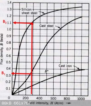
The curve is also useful for understanding why an air gap is required in a choke. Note that in an MOT with the magnetic shuts removed there s no
deliberate air gap between the E and I stacks of laminations. The weld line between the E and I stacks and on other outer faces are there to hold the
stacks together and to reduce noise.
[Edited on 2/25/2024 by wg48temp9]
I am wg48 but not on my usual pc hence the temp handle.
Thank goodness for Fleming and the fungi.
Old codger' lives matters, wear a mask and help save them.
Be aware of demagoguery, keep your frontal lobes fully engaged.
I don't know who invented mRNA vaccines but they should get a fancy medal and I hope they made a shed load of money from it.
|
|
|
wg48temp9
National Hazard
Posts: 761
Registered: 30-12-2018
Location: not so United Kingdom
Member Is Offline
|
|
So below is the B H curve from my previous post with an added curve of an air gap shown in green.
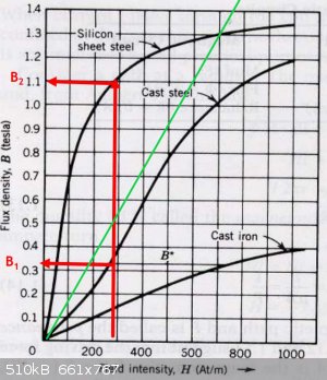
Sorry, I could not add the reluctance of the air gap to the reluctance curve for silicon steel. You have to add the two curves horizontally in your
head. The reluctance of the air is equal to the reluctance of the silicon steel at G2. This significantly reduces then flux and therefore the
saturation, but it also halves the inductance proportional to the flux decease. The inductance can then be restored by increased the number of turns.
So now can I design a 100A air gapped choke using an MOT with the following characteristics:
Original primary
250 turns, 3.2 ohms, inductance 05 H
No load rms current, 1 A
Full load rms current 5 A
Given that the core losses will be greatly reduced because of the reduction in amplitude alternating flux, so I will assume the usually high copper
losses can be the same as the original windings. To keep the same primary copper losses the same as the original winding (5A), with a 100A current the
number of turns must be reduced while keeping the amount of copper unchanged. As current has increased to x 20, so the winding resistance must be
decreased by 400. For a fixed volume of copper, the resistance of a winding is proportional to the square of the number of turns. Therefore, 12.5
turns at 100 A will dissipate the same power as the 5 A did in the original primary winding of 250 turns. The secondary space can also be used, so the
total turns are 25 assuming the original secondary dissipated the same power as the primary. That will have an inductance of 100 time less than the
original primary 0.005 H and halved again to account for the air gap, so the final inductance 0.0025 H.
For full wave rectification of 10 volts...
Sorry, I will have to finish and check this later

[Edited on 3/2/2024 by wg48temp9]
I am wg48 but not on my usual pc hence the temp handle.
Thank goodness for Fleming and the fungi.
Old codger' lives matters, wear a mask and help save them.
Be aware of demagoguery, keep your frontal lobes fully engaged.
I don't know who invented mRNA vaccines but they should get a fancy medal and I hope they made a shed load of money from it.
|
|
|
Sulaiman
International Hazard
Posts: 3562
Registered: 8-2-2015
Location: 3rd rock from the sun
Member Is Offline
|
|
| Quote: Originally posted by yobbo II | . I want to know how you would calculate or estimate the capacitance and inductance needed for this particular type of filter.
Ripply, I don't really know. As little as possible without breaking the bank on caps. The MOT inductor will not break the bank.
|
as a starting point, my quick rule-of-thumb is,
For 1 volt pk-pk ripple using full-wave rectification of a 50Hz supply,
use 4,700 uF per amp dc output.
eg a 100A dc output requires about 0.47 Farad (470,000 uF)
Probably super-caps, or a lot of electrolytics.
An inductor does reduce the value of capacitance required for a given ripple voltage,
and the ripple current requirement of the capacitors.
CAUTION : Hobby Chemist, not Professional or even Amateur
|
|
|
wg48temp9
National Hazard
Posts: 761
Registered: 30-12-2018
Location: not so United Kingdom
Member Is Offline
|
|
| Quote: Originally posted by Sulaiman | | Quote: Originally posted by yobbo II | . I want to know how you would calculate or estimate the capacitance and inductance needed for this particular type of filter.
Ripply, I don't really know. As little as possible without breaking the bank on caps. The MOT inductor will not break the bank.
|
as a starting point, my quick rule-of-thumb is,
For 1 volt pk-pk ripple using full-wave rectification of a 50Hz supply,
use 4,700 uF per amp dc output.
eg a 100A dc output requires about 0.47 Farad (470,000 uF)
Probably super-caps, or a lot of electrolytics.
An inductor does reduce the value of capacitance required for a given ripple voltage,
and the ripple current requirement of the capacitors. |
That looks very optimistic. 100A for 10ms is 1C. 1C into 1 Farad is a change in voltage of 1V ie pk to pk.
I am wg48 but not on my usual pc hence the temp handle.
Thank goodness for Fleming and the fungi.
Old codger' lives matters, wear a mask and help save them.
Be aware of demagoguery, keep your frontal lobes fully engaged.
I don't know who invented mRNA vaccines but they should get a fancy medal and I hope they made a shed load of money from it.
|
|
|
Sulaiman
International Hazard
Posts: 3562
Registered: 8-2-2015
Location: 3rd rock from the sun
Member Is Offline
|
|
you are correct,
I don't remember where I got my rule-of-thumb from but mathematically it is wrong
Sorry all
CAUTION : Hobby Chemist, not Professional or even Amateur
|
|
|
yobbo II
National Hazard
Posts: 710
Registered: 28-3-2016
Member Is Offline
Mood: No Mood
|
|
What would be the incremental permeability (IP) of the steel used in microwave transformers.
The IP is the figure you use (I think) as there is DC present. The usual permeability is not revelant.
Also what would be the saturation flux density of the core?
I am going to use the 'E,s' from two transformer cores. The transformers are cut open, the 'I,s' are discarded and the two E parts are put together
which gives double the space for winding. I will have to put somethig to space the two E parts apart (the gap) put on the windings and then weld the
two E parts together.
Doing calculations I am getting about 1.9mH. Using a gap of 1mm in all three legs, 24 turns, and an (incremental) permeability (a guess) of 200
With a gap of 0.5mm I get 2.63mH.
What a miserable amount of Henry's!
Thanks,
Yob
[Edited on 7-3-2024 by yobbo II]
|
|
|
Twospoons
International Hazard
Posts: 1282
Registered: 26-7-2004
Location: Middle Earth
Member Is Offline
Mood: A trace of hope...
|
|
| Quote: Originally posted by yobbo II |
What would be the incremental permeability (IP) of the steel used in microwave transformers.
The IP is the figure you use (I think) as there is DC present. The usual permeability is not revelant.
|
Since IP is dependent on DC bias there is no single answer to that question.
I suggest you download Femm 4.2 and model your core assuming the use of grain oriented silicon steel.
Thats going to give you better answers than anyone here can give you.
[Edited on 8-3-2024 by Twospoons]
Helicopter: "helico" -> spiral, "pter" -> with wings
|
|
|
yobbo II
National Hazard
Posts: 710
Registered: 28-3-2016
Member Is Offline
Mood: No Mood
|
|
Thanks Twospoons,
Femm may not be too easy to learn? I don't know a whole pile about magnetics.
Yob
|
|
|
Twospoons
International Hazard
Posts: 1282
Registered: 26-7-2004
Location: Middle Earth
Member Is Offline
Mood: A trace of hope...
|
|
Its well documented and there are plenty of examples. It would be well worth your time to learn to use it.
Helicopter: "helico" -> spiral, "pter" -> with wings
|
|
|


