| Pages:
1
2
3
4
5
..
9 |
watson.fawkes
International Hazard

Posts: 2793
Registered: 16-8-2008
Member Is Offline
Mood: No Mood
|
|
Quote: Originally posted by smaerd  | Thanks woelen. Yea it should be a relative reading rather then anything near absolute. That'll help a lot code-wise too. Thanks again seriously.
[...]
I got some 590nm 3500mcd LED's from superbrightleds.com . Have to make a warning that these suckers are bright! Think they'll do much better then the
rinky dinky LEDs I was using in my previous polarimeter(from radioshack). |
It's watson. You're welcome.
As long as you're going to order materials now, make sure to pick up a box of cuvettes. The plastic ones are inexpensive; you should be able to pick
up a box of 100 for less than $20. (Here's the first link I found on Google.) You need these while constructing the apparatus, because you'll want to test-fit the cuvette holder with actual
cuvettes.
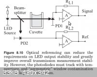
I'd recommend building a cuvette holder into each beam path. One cuvette is empty; the other holds the sample. By this mechanism you null out the
absorption from the cuvette itself. The probably doesn't material affect the accuracy of a version 1.0 device, but it would sure be a pain to put in
after-the-fact. And while this may already be obvious to you, make sure that when the lid is closed that there's no light leakage between the two
optical paths.
Really bright LED's may or may not be the right thing for the device. The photoresistor you're using (or whatever other photodetector) is going to
have both an upper limit and a lower limit of useful sensitivity. At the upper limit, the sensor will saturate, meaning that it doesn't register any
signal difference between different impinging luminosities. At the lower end, there may be a minimum threshold before registering anything at all,
acting much like saturation (but not ordinarily called that). The upshot is that you may need tune the luminosity to match your photosensor. This is
pretty easy to measure once you have your electronics on the breadboard.
|
|
|
smaerd
International Hazard
Posts: 1262
Registered: 23-1-2010
Member Is Offline
Mood: hmm...
|
|
Sorry for the name mixup!
I already ordered a quartz cuvette from ebay for 10 usd for another project I am working on. The cuvettes used in polarimeters are a bit different
they tend to be 10cm long. E-bay has a decent amount of them for about 40USD a piece. The smaller the path-size the smaller the angle of polarization.
For really small path-lengths of sample the farraday modulator type set up is used(applications such as HPLC etc). As it's highly sensitive but has
limitations on how much it can bend light(due to the optical air coil).These types of cuvettes are easy to mount and the way I am designing the device
it will be easy to adjust distances and set up a good optical train with very little hassle. The channel brackets I am using from servocity.com can be
aligned with a 1/2" OD PVC pipe then machine screwed to a board. Learned my lessen about planning ahead for modifications when building the rotary
evaporater the hard way.
The actual absorption of light from these cuvettes should be very small. http://www.almazoptics.com/images/Quartz%20Transmittance.gif , (Transmittance of quartz for 7mm path-length), but you're right this should be
factored in. I also considered the fact that the detector will have an upper limit. I believe LED's typically have a 'relatively' linear luminous
intensity verses forward current relationship, again with upper and lower limits. I'd rather not tinker with that too much. I figured this: I can
always not use these LED's but if the detectors & polarizers I choose works better with more light then it would stink to have to wait a week for
new LED's to arrive to play with and figure it out. I know that in my first design it wasn't very easy to see the polarized light, then again an eye
isn't a detector(at least not one I can interface with a microcontroller).
I figure picking the right detector, polarizer, and light source here will probably be the most critical thing after the rotation is figured out. As
there's a lot of options and I'd hate to settle on something that's just 'Okay' if I can do better without shelling out an entire paycheck.
<!-- bfesser_edit_tag -->[<a href="u2u.php?action=send&username=bfesser">bfesser</a>: fixed
broken link]
[Edited on 31.12.13 by bfesser]
|
|
|
smaerd
International Hazard
Posts: 1262
Registered: 23-1-2010
Member Is Offline
Mood: hmm...
|
|
Alright got a lot of the hard-ware figured out and put together.
Did the PWM circuit and code really basic but it works and I haven't fried my micro-controller *yet*. If anyone is curious about the circuit diagram
or the code for the PWM let me know. Its nothing too intense but it was kind of scary figuring it out.
So up next is the encoder and handling the encoder. Now that the motor is slowed down it should be manage-able though.
I looked into it, and using very bright LED's is probably a good idea after-all. Most dichroic polarizer film only has 80% transmittance in the range
this will be operated from. So two in the optical path is 64% transmittance disregarding anything else put the way. I've been debating not using
dichroic film as its not an ideal polarizer for this application but for version 1.00 it'll be fine and cheap.
Also Watson I was wondering how bad is it to run a TIP type darlington without a heat-sink? It's being used way below its rating(~1/5 voltage) and
ideally won't be run for long lengths of time.
|
|
|
IrC
International Hazard
Posts: 2710
Registered: 7-3-2005
Location: Eureka
Member Is Offline
Mood: Discovering
|
|
The actual absorption of light from these cuvettes should be very small. http://www.almazoptics.com/images/Quartz%20Transmittance.gif...
smaerd not super important but the comma after gif in your link blocks the image. Easy enough to backspace it out and hit reload to see the gif but I
just thought I would mention it. Nice project.
http://www.almazoptics.com/images/Quartz%20Transmittance.gif
Link fixed for you. Also I cannot load the links on the first page, below:
http://projects.markslaboratory.com/polarimeter/
http://projects.markslaboratory.com/wp-content/uploads/2011/...
[Edited on 7-2-2013 by IrC]
"Science is the belief in the ignorance of the experts" Richard Feynman
|
|
|
smaerd
International Hazard
Posts: 1262
Registered: 23-1-2010
Member Is Offline
Mood: hmm...
|
|
It appears this Markslaboratory website has closed down. Shame, the fellow came in here and shared some things with us.
Thanks for fixing that link.
So today I got the encoder on the motor to count pulses over a given span of time with PWM for the motor supply. That's a big chunk down. Now I need
to get a tote or similar to contain all of this in as it's quickly becoming unmanageable with all of the connections and moving parts. Once the
hard-ware is mounted properly I'll be able to focus on the LED's then probably the biggest road-blocks ahead... I'll report back once it gets more
neat to look at  . .
Not too happy about how many power supplies I need for this. I might end up incorporating a cheap computer ATX or SFX(for size) just to deal with all
these. Need 12v, 2x 5v, and an unknown voltage as I haven't hammered out the circuit yet. Don't want to have 3 wall-warts(arduino provides a 5V).
[Edited on 2-7-2013 by smaerd]
|
|
|
watson.fawkes
International Hazard
Posts: 2793
Registered: 16-8-2008
Member Is Offline
Mood: No Mood
|
|
| Quote: Originally posted by smaerd | I looked into it, and using very bright LED's is probably a good idea after-all. Most dichroic polarizer film only has 80% transmittance in the range
this will be operated from. So two in the optical path is 64% transmittance disregarding anything else put the way.
[...]
Also Watson I was wondering how bad is it to run a TIP type darlington without a heat-sink? It's being used way below its rating(~1/5 voltage) and
ideally won't be run for long lengths of time. |
The brightness of your LED can vary by a factor
106 depending on the current you run through it. The sensitivity of even a cheap photoresistor can be 104. You're worrying about
a signal loss of about 100.2, which is unlikely to be your worst problem. Detector saturation is much more likely to be a problem. You're
going to get some absorption in your sample, too.
Experimental techniques to measure the performance of a photoresistor: http://softsolder.com/2009/11/27/measuring-photoresistor-vol...
More that you can handle at present on the physics of photodetectors: http://nanohub.org/resources/9143/download/
If you're worried about power consumption in a part, measure it. Put a voltmeter across the part and an ammeter in line with it. For checking for
conformance to a power dissipation capacity, these don't need to be very accurate, since you want some derating anyway. That means that cheap is fine.
Multiply the voltage drop by the current and you've got your power dissipation. (Or switch a MOSFET, since current-generation devices have on-state
resistances measured in mΩ and not Ω.) | Quote: Originally posted by smaerd |
Not too happy about how many power supplies I need for this. I might end up incorporating a cheap computer ATX or SFX(for size) just to deal with all
these. Need 12v, 2x 5v, and an unknown voltage as I haven't hammered out the circuit yet. Don't want to have 3 wall-warts(arduino provides a 5V).
|
You shouldn't need more than two primary supplies. Using a separate supply for the motor is simply the
easiest way to accomplish some noise isolation. Why do you say you need two 5 V supplies?
|
|
|
smaerd
International Hazard
Posts: 1262
Registered: 23-1-2010
Member Is Offline
Mood: hmm...
|
|
I'm going with a PIN photodiode rather then a photoresistor. I figure I will do an op-amp and feed the data to the Analog pins on the arduino board.
The ATMega chip should do fine for the ADC.
As much as I liked the wheat-stone bridge idea and spent time researching it I came to find out how bad photoresistors can be for measurements and it
scared me off. ( http://www.electronicspoint.com/photodiode-vs-photoresistor-... here there's a discussion about this)
I'm worried about using the 5V pin on the arduino because I don't think it offers much by way of current. Also I will need two detection circuits, two
LEDs, and my motor encoder all on 5V, all on the arduino pin being fed from USB of a computer. I think I'll need to isolate these rather then try and
figure out a way to make that work. Maybe I can get away with running both op-amps on 3.3V. I'll try to hammer that out later I guess...
Here's some simple-ish and cheap shot-noise canceling circuits for lasers, not really LED's but the same principle applies : http://www.electrooptical.net/www/canceller/iodine.pdf
It'll be nice once I can actually hit the soft-ware part of this project hahaha.
I was originally thinking of doing this but I'd rather not flood the ADCs on the ATMega IC.
[Edited on 4-7-2013 by smaerd]
|
|
|
watson.fawkes
International Hazard
Posts: 2793
Registered: 16-8-2008
Member Is Offline
Mood: No Mood
|
|
| Quote: Originally posted by smaerd | | I'm worried about using the 5V pin on the arduino because I don't think it offers much by way of current. |
It's on the spec sheet for the board, at the very least from part on the schematic.
|
|
|
smaerd
International Hazard
Posts: 1262
Registered: 23-1-2010
Member Is Offline
Mood: hmm...
|
|
Well the current comes from the USB. USB maximum draw is 500mA. Hard to say how much the board is using. I could measure it but I'd rather isolate it
for now. So if something goes wrong I can work it out then put it all together.
The 3.3V power pin on the leonardo has a 40mA maximum draw.
I'm a lot more concerned about the photodetection circuit right now and getting it to work at the pace of the encoder. I'm tossing too many ideas
around right now.
I did build a very simple circuit that responded to intense light verses dim light but there was a crapload of noise but atleast I have a tiny
understanding of what to do now. Now I'm thinking I might be able to use a comparator. I'm pretty lost a lot more research to do I guess.
|
|
|
watson.fawkes
International Hazard
Posts: 2793
Registered: 16-8-2008
Member Is Offline
Mood: No Mood
|
|
| Quote: Originally posted by smaerd | | Well the current comes from the USB. USB maximum draw is 500mA. Hard to say how much the board is using. I could measure it but I'd rather isolate it
for now. So if something goes wrong I can work it out then put it all together. |
That seems sensible. I
wouldn't worry about a proliferation of power supply units for now. Use whatever you need for now, while it's in test-bench form, and figure out your
final power supply needs once everything else is working. You may not be able to get away with only 2.5 W draw on the USB (0.5 A x 5 V); your LED
illumination might take all of that itself.
Hint: Wall warts are probably easier to deal with than an ATX supply. You don't need all the power output of those things, and they can have stability
problem driving low-power loads, which your project is.
|
|
|
smaerd
International Hazard
Posts: 1262
Registered: 23-1-2010
Member Is Offline
Mood: hmm...
|
|
Alright I got the soft-ware essentially written and communicating with the microcontroller. Came up with a design that should work for the instrument.
Have the circuit sort of planned out for the photodiode. Only thing is I need a 0.1uF nonpolar capacitor. Seems like only mouser has them and there is
a 17 week wait to receive them. Tried digikey and jameco no luck. Anyone have any supplier ideas?
I also realized I don't need a double beam instrument. The intensity is a relative measurement. Doing three runs should make the results pretty clear.
[Edited on 21-7-2013 by smaerd]
|
|
|
watson.fawkes
International Hazard
Posts: 2793
Registered: 16-8-2008
Member Is Offline
Mood: No Mood
|
|
| Quote: Originally posted by smaerd | | I also realized I don't need a double beam instrument. The intensity is a relative measurement. Doing three runs should make the results pretty clear.
|
The reason for a double beam is to null out variations in the power supply to the LED over time (and to a
lesser extend, supply variations to the detector). Those variations probably do not affect the performance of a version 1 quality instrument, unless
you get a lot of motor noise coupling into the power supply. On the other hand continuous sampling over all angles does something by itself to average
out such variations. Should you ever get to the point of doing a version 2 instrument, a detailed error analysis will give you an idea about how
valuable it is.
Search Mouser under "film" or "multilayer ceramic" capacitors. Those are both non-polar types.
|
|
|
smaerd
International Hazard
Posts: 1262
Registered: 23-1-2010
Member Is Offline
Mood: hmm...
|
|
Okay so I've finally started to make this project more presentable. Over the past few weeks I have made a lot of progress though.
So far I have written the java application to talk to the arduino via serial communication and set up the arduino code to talk back with operations in
place to insert the 'final code'.
This weekend I finally got around to putting this thing maybe 75% together. I decided to buy some new polarizing films as the ones from my last
project were kind of bent or bowed.
Made the light detection circuit just need to put it in parallel with the LED circuit as I don't want to use three wall warts for this device. Later
on I'll probably try something else out so power spikes don't ruin anything.
Next steps are essentially mounting and wiring up the photo detection circuit, polarizing film, painting the box, putting up yellow sheets to absorb
stray light, then digging into some more micro-controller and java code. Hopefully by next week this will be up and running with the errors to trouble
shoot revealed. We'll see how lucky I got hahaha.
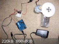
Here are some pictures.
Over-head assembly photo. Bottom left the PWM circuit and arduino. Upper left the motor and encoder wiring. Hidden in the upper left is the LED mount
going through the rotor. Motor with gear mount. In the middle temporary LED bread board circuit, this is where the sample cell will go. To the right
where the photodetector will go.
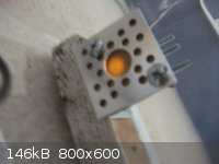
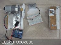
Where the photodetector will be placed behind polarizing film
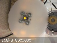
Light source and gear mount
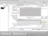
Soft-ware early glimpse
[Edited on 28-7-2013 by smaerd]
|
|
|
smaerd
International Hazard
Posts: 1262
Registered: 23-1-2010
Member Is Offline
Mood: hmm...
|
|
thought I had the transampedance photodiode circuit working but somethings going wrong. I keep getting really wild oscillations on the output. 0 to 5V
back sinuisoidal even when shielded from light. Then I appeared to have a circuit that was sensitive to light but instead of going from 0V(no light)
to 5V(Maximum light) it was going 5V(no light) to about 3V(full light). Did that by 'grounding' the 5V- line to the arduino ground pin. Wasn't
sensitive enough to pick up the LED shining directly on it(in a dark enclosure) either so I'm not sure how amplified it really was.
The original idea was to have the photodiode and LED in parallel on the same 5V wall-wart PSU but I'm beginning to think that's impossible.
Would anyone be able to help me to troubleshoot this? I wouldn't normally ask but I've been at it for a couple of days now.
[Edited on 1-8-2013 by smaerd]
|
|
|
watson.fawkes
International Hazard
Posts: 2793
Registered: 16-8-2008
Member Is Offline
Mood: No Mood
|
|
With no schematic? Come one, you know better than
that. It's the as-built schematic that matters. If you derived it from some publically-available schematic, that would be useful also.
|
|
|
smaerd
International Hazard
Posts: 1262
Registered: 23-1-2010
Member Is Offline
Mood: hmm...
|
|
Right I was just wondering if anyone actually would help me with this. Didn't want to post it and have it sit.
So please keep in mind I'm not an electronics person I'm very new this is the first time I've ever tried to use an op-amp.
The power supply is a 5V 0.5A wall wart. I don't have the information about the LED on hand but can get it if necessary. The resistor in series with
the LED is a simple 270ohm.
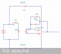
The LED circuit is in parallel with the op-amp photodiode circuit. The op-amp circuit is decoupled with 'C1' which are 100 uF nonpolar film caps. The
photodiode, BPW34(data sheet: http://www.vishay.com/docs/81521/bpw34.pdf) is placed on the +in and -in pins of the LTC1050 chopper stabilized op amp(data sheet: http://cds.linear.com/docs/en/datasheet/1050fb.pdf). the parallel power is connected to the V+ and V- pins respectively.
The In- is also connected to a 10Kohm resistor in parallel with a 0.1uF cap which leads to the Out pin.
The Out pin goes straight to the arduino analog pin for reading. The main difference is the external power supply.
The circuit resembles the second circuit seen here: http://outsidescience.wordpress.com/2012/11/03/diy-science-m...
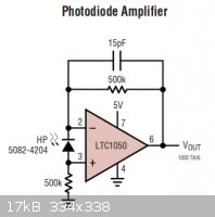
It also sort of resembles the circuit seen in the LTC1050 op amp data sheet:
Here is the super basic arduino code made just for troubleshooting this circuit:
| Quote: |
int inPin0 = 0;
void setup() {
Serial.begin(9600);
Serial.println();
}
void loop() {
int pinRead0 = analogRead(inPin0);
float pVolt0 = pinRead0 / 1024.0 * 5.0;
Serial.print(pVolt0);
Serial.println();
delay(100);
}
|
here is the current output I am recieving from this code under relatively dim lighting:
| Quote: |
4.08
5.00
5.00
5.00
3.96
4.02
4.57
3.78
3.78
5.00
5.00
4.81
5.00
5.00
4.21
4.40
3.91
5.00
5.00
4.08
4.71
4.12
4.08
4.54
5.00
4.45
5.00
4.28
4.34
4.18
4.00
4.42
3.93
5.00
4.40
3.94
4.13
3.96
3.96
5.00
5.00
5.00
5.00
4.07
|
When I completely shield the photodiode from light with a roll of duct tape I get all '5V' readings with a few weird spikes down to about '4.0V'.
I've done a fair amount of research on these types of issues and before I attempt to share my opinion of what I think is going on I'd rather hear what
someone with experience has to say . Any help greatly appreciated.
[Edited on 1-8-2013 by smaerd]
|
|
|
watson.fawkes
International Hazard
Posts: 2793
Registered: 16-8-2008
Member Is Offline
Mood: No Mood
|
|
The + input on the op-amp needs to be grounded. In the sample schematic it's grounded through a 500 KΩ resistor. Look up "virtual ground"
for op-amps to get an idea why. You might also look up "transimpedance amplifier", since that's how the op-amp is configured. If you want to know why
you should consider a photodiode a current source, and not a voltage source, take a look at the data sheet and see how the response is specified.
Is the schematic for those decoupling capacitors correct? Decoupling puts a capacitor from supply to ground at the supply pin of a chip.
|
|
|
smaerd
International Hazard
Posts: 1262
Registered: 23-1-2010
Member Is Offline
Mood: hmm...
|
|
The main confusion for me is grounding. Probably because I've never heard or ran into the term 'virtual ground' before. Now I have a new direction to
look in.
No the decoupling capacitors are probably not correct. I figured they were used just as capacitors in series on the supply simply to tame current
ripple. Looks like I've got it wrong yet again hahaha.
Well much more to research now thanks for the sense of direction.
|
|
|
smaerd
International Hazard
Posts: 1262
Registered: 23-1-2010
Member Is Offline
Mood: hmm...
|
|
well I now have the circuit 'working'. It displays around 1.6 or so V in sunlight around noon through a window. the LED light through the polarizing
films however appears to be a 0.00V to 0.04V. So it looks like I need a new LED, better photodiode (the one I was using was around 0.80$), better
polarizing film, or a better way to collimate the beam. Maybe all Four. Could use a small capacitor as well so I'll get on that as well.
I did work out the decoupling capacitors and all that though. I also kept a 100uF cap in place to stabilize supply ripple.
|
|
|
smaerd
International Hazard
Posts: 1262
Registered: 23-1-2010
Member Is Offline
Mood: hmm...
|
|
The photodiode I was using has poor sensitivity in the 500-600nm range. That could explain a lot. Found one for under 10$ with great sensitivity at
around 550nm.
The LED was 3500mcd(45*) which I considered to be bright. Turns out there are 21000mcd LEDs with smaller view angles(30*) for very cheap(590nm). Going
to try that out. Also ordered a small 270pF cap or three rather then the 0.100uF. Think this will 'fix' the design.
*fingers crossed* Hoping to run to the code as soon as these components come(pretty big factory lead time) and tie this project together. Still have
some serial communication technicalities to hammer out.
If not I will consider using a cheapy polarized laser source the same cell and one polarizer. Just happy to have gotten this far .
[Edited on 6-8-2013 by smaerd]
[Edited on 6-8-2013 by smaerd]
|
|
|
watson.fawkes
International Hazard
Posts: 2793
Registered: 16-8-2008
Member Is Offline
Mood: No Mood
|
|
| Quote: Originally posted by smaerd | | So it looks like I need a new LED, better photodiode (the one I was using was around 0.80$), better polarizing film, or a better way to collimate the
beam. Maybe all Four. |
You could also increase the gain of the amplifier by changing the value of the
feedback resistor. You'll want to do something like that eventually anyway, so that the cuvette-absent path as assembled yields a voltage that is near
the maximum range of the A/D converter.
|
|
|
watson.fawkes
International Hazard
Posts: 2793
Registered: 16-8-2008
Member Is Offline
Mood: No Mood
|
|
| Quote: Originally posted by smaerd | The photodiode I was using has poor sensitivity in the 500-600nm range. That could explain a lot. Found one for under 10$ with great sensitivity at
around 550nm.
The LED was 3500mcd(45*) which I considered to be bright. Turns out there are 21000mcd LEDs with smaller view angles(30*) for very cheap(590nm). Going
to try that out. Also ordered a small 270pF cap or three rather then the 0.100uF. Think this will 'fix' the design. |
Poor sensitivity in the frequency range of the emitter is indeed an unfortunate result. That's bad regardless of the gain of the
amplifier, since it has to do with noise, specifically, the ratio of the dark current to the signal current.
Think of the plastic case of an LED as a built-in lens. Now realize you don't have live with the lens that comes with the LED. Easiest is to use
another little lens to focus the beam. Put the beam waist at the center of the cuvette.
Three 270 pF capacitors yield 0.810 nF, which is three orders of magnitude less than 0.810 μF. But do you know why that capacitor is there at
all? (Hint: filter.)
|
|
|
smaerd
International Hazard
Posts: 1262
Registered: 23-1-2010
Member Is Offline
Mood: hmm...
|
|
Yea its to filter the high frequency noise from the resistive load. Thanks for all the advice on this watson it's meant alot. I'll be reporting back
when mouser ships this stuff.
Edit - oh yea the whole problem with my opamp circuit was where I was grounding from so a little 'calculated' trial and error resulted in what appears
to be success.
[Edited on 6-8-2013 by smaerd]
|
|
|
unionised
International Hazard
Posts: 5104
Registered: 1-11-2003
Location: UK
Member Is Offline
Mood: No Mood
|
|
Did you know that you can use an LED as a photodiode?
It does a good job of detecting the same wavelength that it emits and the coloured plastic case acts as a filter to select out some stray light.
|
|
|
smaerd
International Hazard
Posts: 1262
Registered: 23-1-2010
Member Is Offline
Mood: hmm...
|
|
I was aware of this but they aren't as sensitive/responsive and require a larger resistive load meaning more noise. Although one thing I did notice
with my manual built polarimeter was that the color of light out of the analyzer(polarizing film) appeared as different colors near maxima and minima
of perceived intensity.
I'll be willing to try it out if the new photodiode I ordered doesn't work out. I recall reading that they also can read light at wavelengths lower
than their emission spectra. I found this strange knowing the little bit I know about band-gap theory. Maybe they meant a handful of nm lower but I'd
have to play with a monochromator to know for sure. I think that sort of design would be more useful for a simple colorimeter or special use
fluorimeter. A colorimeter build like that would be a fun way to spend a rainy after-noon.
[Edited on 10-8-2013 by smaerd]
|
|
|
| Pages:
1
2
3
4
5
..
9 |


