| Pages:
1
2
3
4 |
WGTR
National Hazard

Posts: 971
Registered: 29-9-2013
Location: Online
Member Is Offline
Mood: Outline
|
|
For 8-bit 8051 microcontrollers you could try Silicon Labs. I've bought several of their eval boards over the years. The kits come with a JTAG
programmer that can be used to program your own custom boards later on. Some other manufacturers don't allow this; they lock the adaptor down so
that it will only work with the supplied eval board. The free version of their C compiler used to have a 1k code limitation on it, but it looks like
that limitation has recently been removed.
Here's one:
http://www.silabs.com/products/mcu/Pages/C8051F330DK.aspx
|
|
|
bfesser
Resident Wikipedian
Posts: 2114
Registered: 29-1-2008
Member Is Offline
Mood: No Mood
|
|
<strong>IrC</strong>, from <a href="https://atlas-scientific.com/contact.html" target="_blank">what I've seen on their
site</a> <img src="../scipics/_ext.png" />, they populate and solder the boards in-house.
I wanted the bare board so that I could attach Swiss round machined pin headers instead of the ones they used. Honestly, the email response was a bit
rude, in my opinion. They'd probably get more sales if they were more friendly to the amateur experimenter and hobbyist (these days called "hackers"
or "makers"). Because of their attitude, I decided that I'd look elsewhere for similar fabricated boards.
Thanks for the dichloromethane idea; I've never needed to remove epoxy from anything before.
<strong>WGTR</strong>, I recall watching a YouTube video about their low-power 'Gecko' µCs.
<a href="http://youtu.be/qcG4fcNIX7A?t=3m29s" target="_blank">EEVblog #266 - Mailbag</a> <img src="../scipics/_yt.png" />
<a href="http://www.youtube.com/watch?v=1ihszfJAECk" target="_blank">EEVblog #269 - Energy Micro Tiny Gecko</a> <img
src="../scipics/_yt.png" /> (I watched this one.)
[Edited on 23.10.13 by bfesser]
|
|
|
IrC
International Hazard
Posts: 2710
Registered: 7-3-2005
Location: Eureka
Member Is Offline
Mood: Discovering
|
|
If true not a useful place to do business. Not much effort to help you out it would appear yet they refuse.
Quote: Originally posted by bfesser  | | I wanted the bare board so that I could attach Swiss round machined pin headers instead of the ones they used. |
Just do the de-soldering iron job I mentioned and no need for DCM. The entire board need not be de-potted.
Screw em buy the one off ebay I linked. I think it was free shipping anyway.
Just be very careful with it, is how I first saw a naked 741 opamp back around 82. Very cool looking. I fell asleep and the next day saw how badly
many parts had been destroyed. Other parts are even more sensitive such as electrolytic capacitors. Ruins them very quickly.
I should add the 741 still worked if kept in the dark. I built a sine wave oscillator from it and used it like a light Theremin. Was so much fun I
purposely tried other components. Some were not easy or impossible to de-pot. Others were so sensitive to DCM you had to time things carefully or ruin
them.
[Edited on 10-23-2013 by IrC]
"Science is the belief in the ignorance of the experts" Richard Feynman
|
|
|
watson.fawkes
International Hazard
Posts: 2793
Registered: 16-8-2008
Member Is Offline
Mood: No Mood
|
|
Standard material for
decapping chips is concentrated nitric acid. It's standard operating procedure for reverse engineering electronics.
|
|
|
IrC
International Hazard
Posts: 2710
Registered: 7-3-2005
Location: Eureka
Member Is Offline
Mood: Discovering
|
|
| Quote: Originally posted by watson.fawkes | | Standard material for
decapping chips is concentrated nitric acid. It's standard operating procedure for reverse engineering electronics. |
I know it's what I did all day at a job long ago. However it was not my goal in the mishap I mentioned. I was just trying to depot a circuit board
inside a rectangular block of plastic (silicone rubber/sand) immersed in a pressurized tank of warm DCM. Do not have a handy graph but even at 110
degrees DCM is really building up a lot of pressure. Anyway it was not an automated setup and you had to time it carefully or lose the part values on
items such as electrolytic capacitors. I fell asleep for a few hours (had driven most the night to get back to work on time for Monday), woke up, shut
it down. After cooling and emptying the thing I saw this little skeleton staring at me. Obviously my goal was not de-potting the IC's on the board.
Actually only a 741 out of several IC's was eaten so I assumed the plastic composition was unlike the others. Ruined several other parts like
electrolytic capacitors so that I could not see their values. I had planned on reverse engineering the schematic. Had to start over with another board
to do that.
What I had never thought about before was the effect light would have on the operation of IC's and transistors. Seems only obvious when you think
about it. Which I did with a few transistors later just for fun. Oddly a 2SC711 worked better as a photo transistor than a few I had which were
designed that way.
"Science is the belief in the ignorance of the experts" Richard Feynman
|
|
|
bfesser
Resident Wikipedian
Posts: 2114
Registered: 29-1-2008
Member Is Offline
Mood: No Mood
|
|
<a href="http://youtu.be/mT1FStxAVz4" target="_blank">Decapping ICs (removing epoxy packaging from chips to expose the dies)</a> <img
src="../scipics/_yt.png" />
<a href="http://youtu.be/eoRVEw5gL8c" target="_blank">Viewing an active electronic circuit with a scanning electron microscope</a> <img
src="../scipics/_yt.png" />
|
|
|
watson.fawkes
International Hazard
Posts: 2793
Registered: 16-8-2008
Member Is Offline
Mood: No Mood
|
|
| Quote: Originally posted by bfesser | | <a href="http://youtu.be/mT1FStxAVz4" target="_blank">Decapping ICs (removing epoxy packaging from chips to expose the dies)
|
This is Ben Krasnow's video. He's been referenced in this board before for his shop-made supercritical CO2
reactor.
|
|
|
watson.fawkes
International Hazard
Posts: 2793
Registered: 16-8-2008
Member Is Offline
Mood: No Mood
|
|
| Quote: Originally posted by IrC | | I know it's what I did all day at a job long ago. However it was not my goal in the mishap I mentioned. |
I
never said you didn't know it. I mentioned it because other people read the thread, and since you hadn't mentioned nitric acid, other folks wanting to
take apart IC's might just try DCM first before going straight to whatever everyone else uses successfully.
|
|
|
IrC
International Hazard
Posts: 2710
Registered: 7-3-2005
Location: Eureka
Member Is Offline
Mood: Discovering
|
|
watson.fawkes "Standard material for decapping chips is concentrated nitric acid. It's standard operating procedure for reverse engineering
electronics."
As long as you remember it is for reverse engineering an integrated circuit (internally), not for electronic circuit boards in general. Actually not
the entire IC unless dissolving the leads is one of your goals. The second sentence is too broad in scope. Very bad idea to use HNO3 on a board
stuffed with parts. DCM is better than most other solvents for removing potting materials on a board filled with various components. Also consider how
rapidly DCM removes the outer wrapper of electrolytic capacitors. One reason I bought my first digital LCR meter was to measure these capacitors when
I had circuit boards potted with very tough DCM resistant potting materials.
"other folks wanting to take apart IC's might just try DCM first before going straight to whatever everyone else uses successfully"
Good point I didn't think about that. Actually DCM would be a terrible choice for the IC itself, as only one partially dissolved leaving all others on
the board untouched in the case I mentioned. After many hours, when I said I fell asleep I mean it was nearly clock out time when I woke up. Say 7
hours in the DCM, with many other parts on the board turned to goo. Yes you guessed it at that job no one came around often. Many said they were
afraid to go into my lab because of the hazmat signs on the door. Odd as I felt my place was very safe, while often I saw them use things I would have
worn a respirator and gloves to handle.
Still waiting patiently with the board in my ebay cart for bfesser to say the PH board is worth buying. So far no word. For $28 I want someone to
blame if I don't like it.
[Edited on 10-23-2013 by IrC]
"Science is the belief in the ignorance of the experts" Richard Feynman
|
|
|
bfesser
Resident Wikipedian
Posts: 2114
Registered: 29-1-2008
Member Is Offline
Mood: No Mood
|
|
| Quote: Originally posted by IrC | | Still waiting patiently with the board in my ebay cart for bfesser to say the PH board is worth buying. So far no word. For $28 I want someone to
blame if I don't like it. |
Hehe, you can blame me if you like. I won't have funds to order one until I find
employment or a bag of cash at my doorstep (wishful thinking). How about <em>you</em> let <em>us</em> know what you think of
it? You have the expertise and equipment to properly test it, after-all.
I just received a <a href="http://www.raspberrypi.org/archives/5089" target="_blank">RasPi NoIR</a> <img src="../scipics/_ext.png"
/> camera module in the post, this morning (I ordered from Adafruit before the official release). I'm excited to try it out, and hope to have some
interesting photos to share later tonight or tomorrow.
|
|
|
IrC
International Hazard
Posts: 2710
Registered: 7-3-2005
Location: Eureka
Member Is Offline
Mood: Discovering
|
|
bfesser "Hehe, you can blame me if you like. I won't have funds to order one until I find employment or a bag of cash at my doorstep (wishful
thinking). How about you let us know what you think of it? You have the expertise and equipment to properly test it, after-all."
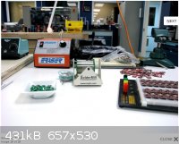
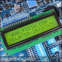
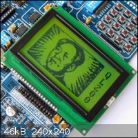
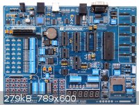
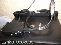
I almost did get the PH board, but I was buying a QL200 which comes with the 1602LCD for $150, and I also wanted the 12864LCD with it which was about
$15 more. So I have to wait on the PH board for a while as this tapped out my experimenting budget for the next while. All this arrived last week so I
am spending every spare minute from work studying what it can do. I will be getting the PH board when I build my hobby cash back up as I am curious
about it. I have not done any studying on the PH board, do you hook a separate PH probe or is it on-board explaining the thick epoxy coat, as in a
bare patch for some type of sensor chip on-board? If so how do you put it in a solution considering the end connectors? Or is the heavy coat to keep
room air away from circuitry (which again leaves me wondering about connectors at each end)? Unsure and if it uses a separate PH probe where do you
get one and what type/model is it? I have never toyed with a processor controlled PH meter firsthand, so I have many unknowns about the subject.
Hopefully I can find somewhere online someone has posted some example code for the PH board.
The pics from the site show green displays (which I don't like), both of the ones I got are blue.
http://www.pic16.com/en/wzcapi/ql200.htm
Forgot to mention: from the site in the link the cost is $135, mine was $150 as I bought it from an in the states seller to get it sooner.
[Edited on 10-31-2013 by IrC]
"Science is the belief in the ignorance of the experts" Richard Feynman
|
|
|
bfesser
Resident Wikipedian
Posts: 2114
Registered: 29-1-2008
Member Is Offline
Mood: No Mood
|
|
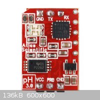
Wow, that board's got a lot going on. Nicely laid out, though. The pH 'stamp' is only potted to frustrate people like me who want to hack it, and to
protect it from crud. You connect two pins to a <a href="http://en.wikipedia.org/wiki/BNC_connector" target="_blank">BNC</a> <img
src="../scipics/_wiki.png" /> jack and use any standard BNC pH probe (they make repeated warnings to keep the stamp to BNC connections as short,
direct, and solid as possible).
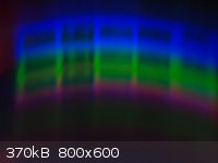
Here are a few images from some RasPi NoIR camera module testing I just did from my couch (I've been sick for the last few days):
<table><tr><td align="center">taken with iPhone (control):</td><td align="center">RasPi NoIR (LED reflections
visible):</td><td align="center">RasPi NoIR + <a href="http://www.raspberrypi.org/archives/5146" target="_blank">filter</a>
<img src="../scipics/_ext.png" /> (used below):</td></tr><tr><td>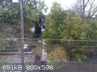 </td><td> </td><td>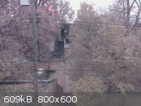 </td><td> </td><td>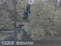 </td></tr><tr><td align="center"><a href="http://en.wikipedia.org/wiki/Normalized_Difference_Vegetation_Index"
target="_blank">NDVI</a> <img src="../scipics/_wiki.png" /> (<a href="http://infragram.org/"
target="_blank">infragram.org</a> <img src="../scipics/_ext.png" /> </td></tr><tr><td align="center"><a href="http://en.wikipedia.org/wiki/Normalized_Difference_Vegetation_Index"
target="_blank">NDVI</a> <img src="../scipics/_wiki.png" /> (<a href="http://infragram.org/"
target="_blank">infragram.org</a> <img src="../scipics/_ext.png" /> :</td><td align="center"><a href="http://en.wikipedia.org/wiki/Near_Infrared#Regions_within_the_infrared"
target="_blank">NIR</a> <img src="../scipics/_wiki.png" /> (red channel):</td><td align="center">blue
channel:</td></tr><tr><td> :</td><td align="center"><a href="http://en.wikipedia.org/wiki/Near_Infrared#Regions_within_the_infrared"
target="_blank">NIR</a> <img src="../scipics/_wiki.png" /> (red channel):</td><td align="center">blue
channel:</td></tr><tr><td>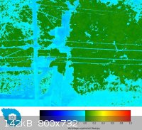 </td><td valign="top"> </td><td valign="top">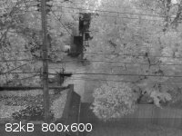 </td><td valign="top"> </td><td valign="top">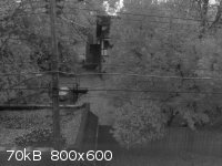 </td></tr></table> </td></tr></table>
I think the NIR is the most interesting—I'm planning on taking a few of my soldering iron and stove-top heating elements. I'm sure there
could be some amateur chemistry applications for this thing, but I can't think of any at the moment—or much else, due to lack of sleep.
When I'm feeling better, I'll try to build and script a portable RasPi Model A + NoIR rig and perhaps try some balloon mapping.
[edit] I just checked, and I apparently (stupidly) emptied my email trash folder since contacting Atlas Scientific regarding the pH stamp. I guess I
have no more info there... but I recall him saying something about the circuit being calibrated with the potting compound in place and the headers
being application specific (BS).
Just an idea I'm tinkering with:
[Edited on 31.10.13 by bfesser]
|
|
|
IrC
International Hazard
Posts: 2710
Registered: 7-3-2005
Location: Eureka
Member Is Offline
Mood: Discovering
|
|
bfesser, I know you mainly work with Raspberry Pi, but I have a question I cannot find the answer to in much searching. I play around with Pics using
C and Picaxe but recently I have been taking a hard look at getting into PicBasic Pro. The program is around $270 which is hard enough to afford, the
programmer that goes with it is the EPIC USB Port Programmer, (melabs U2 Programmer 4.50) yet another $120. This may be showing my ignorance on the
subject but tutorials I find online are cryptic on this subject.
That is, why cannot I use my Pickit 2 or 3, or my K150, JDM, or any one of a half dozen other USB and serial pic programmers I have. I find C very
labor intensive to work with building my little robots and whatnot, do not like Picaxe as well as I thought I would, and started in Basic 30 years ago
meaning I am already very familiar with it. Trying to find a higher level language that does not rip my piggy bank open the way Basic Stamps love to
do. While I found Stamps much simpler they are a rip off in price (as we have discussed before). I have no doubt the lack of an answer to my question
is not by accident, melabs has every incentive to get me to hand them another wad of cash and they can do this by making the answer I am looking for
difficult to locate.
In simple terms what is so special about the melabs U2 Programmer that I must buy it instead of using any one of the dozen or more pic programmers I
already own. Maybe at 60 I'm getting too senile to figure it out but I cannot find the reason I cannot use my own programmers. Also I just got an
MPLAB ICD2 in circuit debugger-programmer I have yet to find time to toy with. Correct me if I'm wrong but shouldn't melabs give a list of programmers
one could use after you have handed them $270 instead of staying silent on the subject and pushing their U2? This link is the U2:
http://store.melabs.com/prod/programmers/U2BUN.html
The picaxe has a bootloader which is their basic interpreter similar to the proprietary code that runs the basic stamp. The reason I ask this question
is I do not know if this U2 is set up in a similar way with a built in interpreter, looking at the board I sure cannot see why it must cost so much to
build they must have $120 for it assuming it is no more than just another programmer.
"Science is the belief in the ignorance of the experts" Richard Feynman
|
|
|
bfesser
Resident Wikipedian
Posts: 2114
Registered: 29-1-2008
Member Is Offline
Mood: No Mood
|
|
My first programming language was BASIC, but I prefer C++ now. I'm not familiar with those programmers or the PicBASIC Pro, but I'll see what I can
find.
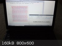
In the mean time, I thought I'd mention that two weeks ago, Wolfram Research released a binary of Wolfram Mathematica for the Raspberry Pi for free!
I've downloaded and installed it on a Pi, but haven't learned how to do anything with it yet.
<a href="http://www.raspberrypi.org/archives/5282" target="_blank">The Wolfram Language and Mathematica on Raspberry Pi, for free</a>
<img src="../scipics/_ext.png" /> (Rasberry Pi Foundation)
<a href="http://blog.wolfram.com/2013/11/21/putting-the-wolfram-language-and-mathematica-on-every-raspberry-pi/" target="_blank">Putting the
Wolfram Language (and Mathematica) on Every Raspberry Pi</a> <img src="../scipics/_ext.png" /> (Wolfram Blog)
<a href="http://www.wolfram.com/raspberry-pi/" target="_blank">wolfram.com/raspberry-pi</a> <img src="../scipics/_ext.png" />
I've used this as a browser homepage off-and-on for a few years:
<a href="http://www.wolframalpha.com/" target="_blank">Wolfram|Alpha: Computational Knowledge Engine</a> <img src="../scipics/_ext.png"
/>
|
|
|
smaerd
International Hazard
Posts: 1262
Registered: 23-1-2010
Member Is Offline
Mood: hmm...
|
|
Thanks for that bfesser just scooped up a raspberry pi and a lap-dock for Wolfram Mathematica alone! That soft-ware is so powerful. We used it in my
ordinary differential equations course and it was incredibly useful. As I am self-teaching partial differential equations this will be of great
utility. Originally I was going to use a touch-screen and make a tablet but I figure I could use the keyboard as typing mathematical equations by
poking a screen sounds over-bearing, and it is significantly cheaper.
Cheers!
|
|
|
IrC
International Hazard
Posts: 2710
Registered: 7-3-2005
Location: Eureka
Member Is Offline
Mood: Discovering
|
|
http://www.marginallyclever.com/blog/2011/10/controlling-you...
Found a useful link for the Arduino, plus following other links from the page yields other project ideas. If one builds an automated setup for an
experiment, the link above would be handy code to allow for changes on the fly to control things. I was thinking along the lines of a runaway reaction
for example.
"Science is the belief in the ignorance of the experts" Richard Feynman
|
|
|
bfesser
Resident Wikipedian
Posts: 2114
Registered: 29-1-2008
Member Is Offline
Mood: No Mood
|
|
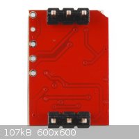
So, on the subject of the Atlas Sci. <a href="https://www.atlas-scientific.com/product_pages/embedded/ph.html" target="_blank">pH
Circuit</a> <img src="../scipics/_ext.png" /> from earlier. I've managed to find a couple high-resolution photos where the markings on
the ICs can clearly be read. The board uses a <a href="http://www.scimad.org/users/bfesser/datasheets/PIC16F1825.pdf"
target="_blank">PIC16F1825 μC</a> <img src="../scipics/_pdf.png" />, a Texas Instruments chip marked "01 P2262" which I have yet
to identify (I'm assuming it's a precision amplifier and/or ADC), and a (regulator?) IC marked "PFKI". Atlas Sci. has also started selling the
potting epoxy they use, on their site.
[photos removed, better below]
I have no experience with PIC programming. Are they similar to AVRs in the ability to read out the flash memory and save it to a binary file for
copying to other PICs?
[Edited on 6.1.14 by bfesser]
|
|
|
smaerd
International Hazard
Posts: 1262
Registered: 23-1-2010
Member Is Offline
Mood: hmm...
|
|
So I realize this isn't directly chemistry related but here's the raspberry pi 'lap-top' I built. Runs mathematica okay. Takes some time for vector
plots to be processed but thats not a big surprise. Kind of slow but considering it does have basic word-processing capabilities(libre office), and
basic web-browsing(slow transfer rates) and only costed me 130(USD)$ it's pretty great. The real beauty of these hacked 'lapdocks' is the 'brain' of
the computer can be swapped out at will with essentially any of the common microcontrollers (minus arduino types). It will suit me through my last
year or so at school and for the cost beats buying mathematica out of pocket.
Please ignore the curled and rubber-banded USB cable, a USB male to male extender is on it's way and the set-up will be more 'practical'.
Nice post IrC. Reminds me I need to get off my lazy ass and get back to tinkering and experimenting.
|
|
|
WGTR
National Hazard
Posts: 971
Registered: 29-9-2013
Location: Online
Member Is Offline
Mood: Outline
|
|
| Quote: Originally posted by bfesser | | a Texas Instruments chip marked "01 P2262" which I have yet to identify (I'm assuming it's a precision amplifier and/or ADC) |
TLC2262CPW
http://www.ti.com/lit/gpn/tlc2262
|
|
|
bfesser
Resident Wikipedian
Posts: 2114
Registered: 29-1-2008
Member Is Offline
Mood: No Mood
|
|
Very nice, smaerd. I've been using my RasPis connected to my TV through HDMI or 'headless' (no monitor, keyboard, mouse) with
SSH/VNC. I've been considering purchasing a small HDMI monitor that I can set on the tabletop, but your solution seems much nicer. Do you have a
model number or link for that lapdock? (And by all means, post whatever you'd like, it doesn't have to be directly chemistry related!)
Thank you so much, WGTR! I had already checked that part and downloaded the datasheet, but didn't see the package (p.72) on my first
look at it, so I had assumed I had the wrong part. Time to get down to business reverse engineering the thing from photos and pinouts on datasheets.
[edit] Clearer photos... thanks SparkFun!
[Edited on 6.1.14 by bfesser]
|
|
|
smaerd
International Hazard
Posts: 1262
Registered: 23-1-2010
Member Is Offline
Mood: hmm...
|
|
It's important to mention that doing this with a Model A raspberry pi isn't as facile. The Model B revision 2.0 only requires two cords and is very
simple to do. The Model A's require cord splicing, little bit of soldering and heat-shrink tubing and I believe takes up another USB port.
The lap-top portion of the project comes from a Motorolla Droid "Lap-dock" . These have been taken off the shelfs and originally retailed for $500
USD. Now they can be found on E-bay 'used' but in good quality for around 40 USD. In all honesty I speculate as to whether mine was ever used. Typing
into e-bay "Motorola Droid Bionic Lapdock" should be a fruitful result  .
Apparently the product flopped on the market and is essentially becoming E-waste, so it's kind of a nice way to bring it a second life rather then let
them go to the dump. Battery life is about 6 hours or so. The lapdocks feature two accessory USB ports(which the rPi can read), a power cord jack, a
battery check display, and supposedly speakers. For wireless internet access I use a 'WiPi' USB dongle that I purchased on the order of about 10 USD. .
Apparently the product flopped on the market and is essentially becoming E-waste, so it's kind of a nice way to bring it a second life rather then let
them go to the dump. Battery life is about 6 hours or so. The lapdocks feature two accessory USB ports(which the rPi can read), a power cord jack, a
battery check display, and supposedly speakers. For wireless internet access I use a 'WiPi' USB dongle that I purchased on the order of about 10 USD.
A few cables are needed to make the connections however. I needed to purchase a micro HDMI female to female connector(china/ebay), and a micro HDMI
male to HDMI male wire for the HDMI connection. I also needed to purchase a female micro (I believe) USB to female USB cord(china/ebay) and a male to
male USB connector. There are some draw-backs to this but it is incredibly work-able. It should be noted that people who have purchased low quality
HDMI cables have suffered from their project not working. I purchased mine along with my rPi and case at MCM electronics was 6inchs in length(~15cm)
for a few dollars. The cable must be grounded at CEC and DEC iirc so it can be luck of the 'draw' supposedly. I never had this issue so I can only
speculate.
Many people use the Motorolla 100 and 500 model but my Droid Bionic worked just fine after making some slight adjustments to the configuration file in
the Raspbian Wheezy operating system(nothing major at all). Adjustments so that the full screen resolution of the lap-dock could be utilized, and that
HDMI was recognized on booting.
The largest draw-back is probably that there is no shut-down button. The computer must be shut-down as it is typically done through terminal and
either the screen closed or the HDMI cable removed from either the rPi or the lap-dock. Many people become frustrated that when the screen is closed
power is cut to the rPi. This doesn't bother me at all and I have seen no reason to hack around this what so ever. Also there are some slight
annoyances like getting a proper keyboard map(european default on Raspbian Wheezy?), and audio to work. I see no real need for audio on this device
personally and carry an MP3 player for such purposes. I'm not sure if the battery drains at all when the case is closed I know the rPi expresses no
power or activity through it's LED's. Either way I disconnect the cords for transport or storage.
One finishing touch type thing that I did was purchased some adhesive velcro pads from a home improvement store and stuck them to my rPi case and the
back of the lapdock screen itself. Was a 3 USD fix and it in my opinion makes the lapdock more portable.
For 'performance' type applications it might be worth checking out an android mini-pc or similar. Supposedly the beaglebone blacks and I believe the
pandaboards can be used in this same manner to create a hacktop/laptop/whatever.
Anyways, now I'm really rooting for a 1gb ram rPi with a faster processor. Hopefully the future delivers on this because it would be nice to have a
cheap laptop with mathematica on-board.
[Edited on 6-1-2014 by smaerd]
[Edited on 6-1-2014 by smaerd]
|
|
|
WGTR
National Hazard
Posts: 971
Registered: 29-9-2013
Location: Online
Member Is Offline
Mood: Outline
|
|
The little "PFKI" component on your board is the TPS60400DBV:
http://www.ti.com/lit/ds/symlink/tps60400.pdf
It's a switched-capacitor voltage inverter, to supply negative voltage to the op-amp.
|
|
|
bfesser
Resident Wikipedian
Posts: 2114
Registered: 29-1-2008
Member Is Offline
Mood: No Mood
|
|
In order to determine the feasibility of cleanly de-potting the pH circuit, I've sent an email to Info@atlas-scientific.com (hopefully they don't see
this before replying): | Quote: | | I'm considering purchasing your Clear Potting Compound Kit, but am concerned about the health effects of inadvertent exposure to the components.
Could you please supply MSDS for the two bottles, so that I can perform a risk assessment before purchasing your product? Thank you for your time.
|
It's difficult to pretend that you're chemophobic and 'dumb' in such correspondence, but I've tried. I have
little actual intent of purchasing the <a href="https://www.atlas-scientific.com/product_pages/kits/pc_clear_kit.html" target="_blank">potting
kit</a> <img src="../scipics/_ext.png" />, at this time.
|
|
|
IrC
International Hazard
Posts: 2710
Registered: 7-3-2005
Location: Eureka
Member Is Offline
Mood: Discovering
|
|
| Quote: Originally posted by quantumchromodynamics | | Specifically does anyone know of or have ideas about hardware that might attach to a drip valve of a separation funnel? A gear down stepper motor
attachment? Is there an existing protocol for interconnecting heating mantles, stirrers, shaker tables, video reaction monitoring, etc? For me the
software and the feedback control algorithms are the fun part. What seems missing are the sensors and the hardware to automate a reaction in
glassware. RC airplane servo motors seem like a good start. |
I never noticed this post before. Assuming the valve can handle the chemical going through it you might look at this:
http://www.allelectronics.com/make-a-store/item/SOL-132/SOLE...
Another idea I had was say the pressure switch below was in line (or on a side port with a T by blocking one port), and when pressure in the system
reached 1 PSI a signal to the computer could close the above valve to reduce the reaction rate. Or be used to trigger some function.
http://www.allelectronics.com/make-a-store/item/PSW-15/PRESS...
Even a solenoid could be used, say above a certain temperature in a runaway reaction the whole mess was dumped into ice water as example.
http://www.allelectronics.com/make-a-store/item/SOL-102/MINI...
Others:
http://www.alltronics.com/cgi-bin/item/28B022/search/Parker-...
http://www.alltronics.com/cgi-bin/item/24B039/search/MAC-34B...
http://www.alltronics.com/cgi-bin/item/24Z074/search/MAC-411...
http://www.alltronics.com/cgi-bin/item/24Z075/search/MAC-421...
http://www.alltronics.com/cgi-bin/item/91Z005/search/CKD-AB4...
No doubt the types of gases or chemicals would be limited by the material the valves are made of. These are just some examples available from a couple
of the electronic surplus stores I buy from. A search on ebay might even yield an electric valve able to handle a greater range of chemicals.
"Science is the belief in the ignorance of the experts" Richard Feynman
|
|
|
smaerd
International Hazard
Posts: 1262
Registered: 23-1-2010
Member Is Offline
Mood: hmm...
|
|
I was trying to think of ways around this issue myself some time ago for a different project. There's really no 'simple' way to go about it. The
cheapest ideas I conjured up were pretty similar to yours IrC. Expensive ways to go about it are things like rheodynes and what not.
The first was a simple pinch solenoid type valve. Make a simple 'manifold' and slam the solenoid down on some hosing when you want to stop the flow.
Issues with that are material wear. I dreamed of making a manifold by punching holes into some aluminum block with a drill press and sealing the
solenoid with o-rings etc. It's probably too much effort although it 'could' be affordable if it worked... Hopefully the description there wasn't to
vague.
The other and my favorite option was essentially a cheapy peristaltic pump-head rigged to a cheapy servo(180* maximum rotation is fine!) controlled by
a micro-controller. Here's the twist; rather then having 3 or 5 'spokes' spinning around the hose only have 1. Turn 180 to rotate the spoke into the
hose shunting it's flow. Turn 180 to rotate the spoke away from the U shaped bent hosing to allow the flow. This shouldn't do much damage to adequate
tubing (IE tygon) as peristaltic pumps can run for many rotational cycles before it is recommended that tubing is replaced. Depending on the
application this tubing may never have to be replaced. It is also quite cheap if done properly and uses significantly less energy then servo's do for
on or off holding power. With PID or perhaps even rudimentary PD control any resistance met by the flow could be countered by applying current towards
the direction of said flow (which wouldn't be an issue for small volumes at low vertical displacements I think?). The down-side is that peristaltic
pump heads are U-shaped and gravitational flow would be hindered by this. Or more simply a peristaltic pump could be the bottom line as to whether a
solution goes or doesn't go rather then gravity.
I considered a few other ideas, but real chemically resistant valves and other-wise cost large amounts of money. Even second hand. For example passing
a hot corrosive runaway solution through the majority of materials will lead to problems. It has to have context. For purposes of automation there are
a number of ways to go about doing things and it depends on the accuracy/resolution of the experimental design and of course what is available.
(last edit I swear) 'Dosing' to my understanding is how people over-come things like valves and volumetric delivery for a lot of situations. How much
and what to dose in a dynamic system is tricky and requires some kind of monitoring. For separations well that's a whole 'nother situation.
The ideas involved in DIY automation could be a thread or sub-forum unto itself.
[Edited on 7-1-2014 by smaerd]
[Edited on 7-1-2014 by smaerd]
|
|
|
| Pages:
1
2
3
4 |


