| Pages:
1
..
27
28
29
30
31
..
47 |
dann2
International Hazard

Posts: 1523
Registered: 31-1-2007
Member Is Offline
Mood: No Mood
|
|
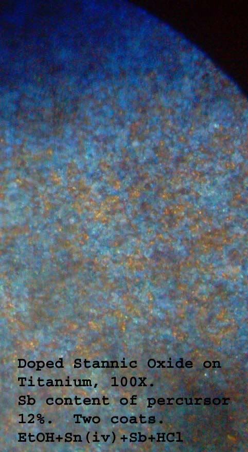
Behold the Elephant
Hello,
I have seen the Elephant..................and it is blue.
The pic. below is not great (taken with cheap camera held to microscope optic) but the blue
DTO can be clearly seen. The yellow(ish) bits are bare Ti metal. They are more grey
than what is showning in the picture. This piece only got two coats (and two bakes).
I think that the secret of getting coats of DTO is to expose the Ti metal to the solution for
a sensible period of time, (say an hour or more), then dry off. All my attempts up to yesterday
(when I did the shake and bake thing) were dried off immediately with a heat gun. When the
'shake and bake'(insert R with circle here :-)) was performed, I left the wet Ti sitting for about
an hour to let it drip or dry. I then dried it slowly using a flame. Ti had lots of exposure to solution.
At least thats what I think. Thought it may have been the change to Ethanol (from Iso P Alcohol)
but now I do not think so. I am currently soaking (overnight) three Ti strips in different persursor
solutions using Ethanol, Methanol and IPA to see if different solvents make any difference.
Also (as Eclectic mentioned in above post) puddle are bad news, you need to shake or actully bang the anode on something to shake all the extra
solution off. Shake, bang and bake, HTF do y get that R-with-circle in here!
The coated Ti looks blackish when viewed with the eye BTW. I tried rubbing with fine steel wool
(OOOOO grade) but this strips off the DTO. When put into a Chloride solution and used as an anode
the voltage is low(5.0 V). This is lower than the other Ti strips I tested (which failed minutes after anyways).
Think it's time to wheel out the Lead Nitrate tank.
Dann2
P.S. "Seeing the Elephant" was a saying amongst gold miners in California in the 1800's which described seeing a line of gold or a big nugget or
nuggets.
Not half as good as seeing glue gold(IMHO).
|
|
|
jpsmith123
National Hazard
Posts: 764
Registered: 24-6-2005
Member Is Offline
Mood: No Mood
|
|
Dann, do you have any cobalt sulfate, acetate, etc., so you could do a comparison between the two contenders?
|
|
|
Rosco Bodine
Banned
Posts: 6370
Registered: 29-9-2004
Member Is Offline
Mood: analytical
|
|
| Quote: | Originally posted by Eclectic
There is absolutely NOTHING wrong with using HCl if you are using tin chlorides. You need some in your solution to prevent premature hydrolysis.
|
"Premature" hydrolysis ??????
There's the controversy you see which has us at loggerheads over this whole bugaboo involving DTO .
First be it acknowledged that the hydrolysis is going to proceed through certain stages as the HCl containing liquid is heated and dried on the Ti ,
but this in situ reaction which
proceeds through various stages is a variable layer chemistry
reaction of overlapping swirls and zones of various unpredicatable composition , a quiltwork of unpredictability ratewise and encouraging granulation
rather than an even contiguous layer of constant composition .
That is resolved by using a higher intermediate as the precursor for the coating , something that eliminates
the variability which would precede its formation in situ .
The mixed valency polymer , or a sol , or stannate compositions being examples of such "higher intermediates" .
| Quote: |
The heat drives it off, and it can keep the Ti surface clean while tin and tin oxides are laid down. |
The heat doesn't drive off the growing TiO2 layer which is the undesired byproduct of such fluxing , it simply builds thickness for the very material
which is problematic , making
doping of that layer more difficult . And the loss of the volatile chlorides of the intended dopant materials is variable and unpredictable , leading
to a product composition
that is unrepeatable with any certainty , even if the target composition is reached . There will be regions on the surface where the desired
composition was achieved , and 3 mm away on the same surface an entirely different composition
is likely . This is a grand recipe for patchwork variability .
| Quote: |
There IS a problem with using so much solution that you have puddles of standing liquid. Many thin coats between bakes, not all at once.
|
Yeah , the one place where this approach might be more
forgiving is spray coating onto an already near red hot surface , where a nearly instantaneous "flash reaction"
upon an aerosol produces a randomness by virtue of the
small particles , which accomplishes the homogeneity in fusion that using a sol dispersion in the first place would provide directly .
|
|
|
Eclectic
National Hazard
Posts: 899
Registered: 14-11-2004
Member Is Offline
Mood: Obsessive
|
|
@Rosco
I'm just saying you can't avoid HCl in a coating solution that uses SnCl4. Nothing at all inadvisable about using a thick prepolymerized DTO
solution. The soak-etch, Shake'n Bake ® approach should "tinnate" the bare Ti surface and protect from TiO2 formation when applying later coats.
( ® "Character Map" ®)
Also, if you have SnCl2 in the etch-coat solution, you are likely going to form conductive titanium suboxides (Ebonex), which is all to the good.
[Edited on 11-28-2007 by Eclectic]
|
|
|
Rosco Bodine
Banned
Posts: 6370
Registered: 29-9-2004
Member Is Offline
Mood: analytical
|
|
Think about the possibility of using the "doped" mixed valency polymer where the dispersion of the dopant is already approaching perfection as a
molecular arrangement and the globules of that material are a sol of nano-scale colloidal particles themselves which are electrostatically charged to
the point they will even adhere persistently to teflon , so tenaciously that you can't wash the stuff off .
And think about what would probably happen when that material contacts a hydrided titanium substrate . The
stuff would be like two rare earth magnets smacking together , and then a chemical bonding would follow with the titanium and the still present though
greatly reduced
chlorine content of that polymer which has an "oxychloride" sort of branch . You would still have a slight fluxing action there on baking , but it
would be in a very much more controlled and specifically limited way , probably along the interface in a layer one molecule thick
instead of through a zone layer that would just keep growing in thickness as with HCl . Also you have the viscosity as a plus with that sol , forming
a thicker layer
upon dehydration , whereupon the polymer remains intact
like a sheet of varnish until baked to its decomposition temperature . And during the baking the polymers doping doesn't change because the higher
precursor is already beyond that stage in the hydrolysis where volatile chlorides are there to be lost during baking , carrying the dopant with them .
Basically the process is the same as when using the HCl
but it begins at a further point along in what would otherwise be an in situ reaction . This sort of reminds me
of that calcium cyanamide synthesis where you can start with urea and calcium carbonate and deal with the byproducts and gas phase reactions , which
lead to
a calcium cyanurate intermediate .....or you can just cut to the chase and start there in the first place , eliminating
all the variables and hurdles which must be passed in
a lengthier path to that intermediate .
It's the same idea here , since the sol dispersion is formed in situ , using the HCl containing mixture which must pass through hydrolysis in an
uncontrolled way during baking ,
forming the sol as an intermediate . Why not simply shortcut the process by forming that intermediate in a controlled way which optimizes its
composition in advance ,
and then start with that higher intermediate as the coating , in order to cut to the chase , nearer to the
end product of the baking ?
dann2 seems absolutely determined to accomplish two conflicting goals simultaneously , to use the highest level
of Sb doping possible , while at the same time using the method of coating which will keep the least amount of the Sb dissolved in the SnO2 , without
it dropping out as a separate phase and causing granulation . The amount of
Sb dopant that can be held contained within the SnO2 is directly limited by the particle dispersion size in the sol , and the only way of minimizing
that particle size to maximize the Sb content of the sol , is to form that sol in advance under very controlled conditions , which are very much
different from the conditions where the sol forms in situ on baking .
There is zero likelihood of ever having so much dissolved Sb in the SnO2 as the end result of baking , unless the
Sb chloride is bypassed by making it a hydrosol in advance . And not doing that , islands of the variably
doped SnO2 , along with separate phase Sb oxide is
inevitably what will be produced by ignoring the physical chemistry of what governs this intended continuous doped layer formation . Again , an
atomized mist applied
to a hot surface could work okay for the HCl rich mix .
But other methods are likely to produce a speckled uneven coverage because that is simply the nature of the beast .
|
|
|
Eclectic
National Hazard
Posts: 899
Registered: 14-11-2004
Member Is Offline
Mood: Obsessive
|
|
I don't think we are essentially in disagreement. 
Except that I think the nature of the beast is that is too complex for any one approach or viewpoint to adequately comprehend.
As in the blind men and the elephant, what seem to contradictions may only be incomplete perception. Let everyone follow their own path on our search
for the holy grail of the perfect electrode.
Can I get an AMEN!?
[Edited on 11-28-2007 by Eclectic]
|
|
|
Rosco Bodine
Banned
Posts: 6370
Registered: 29-9-2004
Member Is Offline
Mood: analytical
|
|
How do we do that "K" inside the circle thing for Kosher
When we get this thing to work , it will definitely be time
to break out the

.....
Maybe if we just upload a virus to the mother ship ,
then we can get through its damn shield
And then , the victory dance
[Edited on 28-11-2007 by Rosco Bodine]
|
|
|
dann2
International Hazard
Posts: 1523
Registered: 31-1-2007
Member Is Offline
Mood: No Mood
|
|
Hello,
FIRSTLY, some answers to important questions :-|
NO, you cannot have an AMEN!!!
As for breaking out the Manischewitz, I have ran out of absolute Ethanol, two gallons, and I havent made than much precursor
Anyhows, moving on to less serious things, I made three precursors using Methanol, Ethanol and IPA to see if solvents were making the difference. They
are not. The three strips of Ti look the same (under microscope) though I have not got around to testing them in NaCl as an anode.
Made up two other percursor solutions using 50/50 Sn(iv) and Sn(ii) + the other usuals. The Ti strip was blotchy and did not last long in the NaCl
(few minutes).
Next up was SnCl2 (+the other usuals). Did not look too good but it is holding up in the cell not too badly. It has been going for about 0.75hours.
The voltage is a bit higher than the DTO Ti strips that were made using Sn(IV). I expect it to fail though, perhaps it will not. Both of the above
strips did not look too good under microscope. I cound only see (what I thought was) DTO in places.
Did not get around to trying percursor without HCl.
What is a 'cook book' recipe for a sol-gel method. Do I have the chemicals??
Edit:
I was thinking (in desperation a few days ago) about using a spray perfume bottle to spray percursor onto hot Ti.
May be possible to heat the Ti by passing power through it. It is hot in that oven, the Ti is a dull red when viewed in the dark. It would oxidize
before it was up to heat though. Perhaps a blanket of propane (yikes). I have no inert gasses.
Dann2
[Edited on 29-11-2007 by dann2]
|
|
|
Eclectic
National Hazard
Posts: 899
Registered: 14-11-2004
Member Is Offline
Mood: Obsessive
|
|
I think the hot Ti spraying is not viable for the initial coating. Surely the Ti would oxidise rapidly. Maybe to build up subsequent coatings, but
you have to get something on the bare Ti that will prevent further oxidation.
Evaporation of mixed SnCl2 and SnCl4 DTO solutions on a hot water bath 1-3 days, topping up with HCl occasionally to prevent crystallization got me a
yellowish solution the consistency of pancake syrup. Very dense, probably 75% solids. I have a medium glass frit filter to remove insolubles.
|
|
|
Rosco Bodine
Banned
Posts: 6370
Registered: 29-9-2004
Member Is Offline
Mood: analytical
|
|
Something special is needed for the initial coating , something that will blanket the titanium completely on the first baking .
jpsmith 123 has started a thread on hydriding of titanium and the patent in that other thread reports a simple coating of nitrates applied to hydrided
titanium then baked at 150C provides a conductive interface and then subsequent build coats provides a working anode .
150C is an easy toaster oven temperature .
Very possibly this can be used as an alternative to DTO
which is more straightforward as substrate preparation
for electroplating heavier working coatings for anodes
useful in perchlorate cells .
With regards to the sol-gel precursor , that is probably what Eclectic has gotten as a syrupy product of his own variation on a patent method posted
five pages back in this thread
http://www.sciencemadness.org/talk/viewthread.php?goto=lastp...
The relevant patent is US3890429 linked here
http://www.sciencemadness.org/talk/viewthread.php?action=att...
Attachment: US3890429 STANNIC_OXIDE_POLYMER_Film Wetting Agent.pdf (399.45 KiB)
I haven't reduced the patent described process to a summary recipe .
Another possibilty as a first coating would be the mixed ammonium stannate / ammonium antimonate composition
described in a patent posted in the
Perchlorate manufacture (not) with Graphite thread on page 4. It is a straightforward process .
http://www.sciencemadness.org/talk/viewthread.php?goto=lastp...
US6777477
http://www.sciencemadness.org/talk/viewthread.php?action=att...
Attachment: US6777477 Sb2O3 doped SnO2 via ammonia soluble derivative.pdf (67.31 KiB)
An advantage for these is the percentage of dopant to
solvent oxide will not change much on baking from what is
in the precursor mixture . The composition will then be easier to fine tune and also to get repeatable results .
[Edited on 29-11-2007 by Rosco Bodine]
|
|
|
dann2
International Hazard
Posts: 1523
Registered: 31-1-2007
Member Is Offline
Mood: No Mood
|
|
@JP. Sorry JP, fotgot to answer you yesterday. I have lots of Cobalt Sulphate. I thought I read a patent or artical
somewhere that used Cobalt Sulphate in a plating bath to plate Cobalt Oxide but I cannot fine it now.
Most of them seem to use Cobaltous Chloride. Guess I can easily make Cobaltous Chloride from Co Sulphate
+ Calcium Chloride. Would this be correct? Will I get Cobaltous Chloride? The 'Cobalt Sulphate' that
I have is Cobaltous Sulphate AFAIK. It gives a deep red colour in solution.
When depositing MnO2 (the Mn Oxide we want) you must have your solution at 90C or you will get the wrong Oxide.
Tested the Ti strip coated in DTO Oxide (using IPA as solvent in percursor). It has been running now for 16 hours @ about
27mA per cm squared (who needs LD eh). The voltage is low (5v) and steady. The strip received five coats (5 bakes).
It is a blue/black colour. I must have some harvestable Chlorate in me jam jar (test cell) with all the testing I have done.
Will attempt to coat DTO'ed Ti strip with Co Oxide.
There is some stuff about Co Anodes on my page under Anodes. They use Formaldehyde in the bath. Also use Co Chloride, all the stuff is OTC.
I was going to attempt to coat Tungsten with some DTO. W is OTC as a welding electrode. It will not etch is hot HCl. Will
try connecting +VE to it when in the HCl.
Also tried using SnCl2 as a percursor for DTO coat. The anode failed after about one hour. The voltage was somewhat higher
at the start of test too, about one volt. It started to rise after about half an hour.
Also tried 50/50 SnCl2 SnCl4 (did I say this further up??) anode fail almost immediately.
Will read up on the sol-gel stuff.
Would have prefered a small terse (working) recipe .....like the examples in the Diamond Shamrock patents..............
Dann2
|
|
|
Twospoons
International Hazard
Posts: 1284
Registered: 26-7-2004
Location: Middle Earth
Member Is Offline
Mood: A trace of hope...
|
|
This paper is really just food for thought. Of note : "crackfree films of TiO2 on 316 stainless", thermal annealing of the electrodeposited films
increased density and crystalisation.
It makes me wonder if we could successfully coat plain old stainless steel.
Attachment: ValveMetalThinFilms.pdf (114kB)
This file has been downloaded 801 times
Helicopter: "helico" -> spiral, "pter" -> with wings
|
|
|
Rosco Bodine
Banned
Posts: 6370
Registered: 29-9-2004
Member Is Offline
Mood: analytical
|
|
| Quote: | Originally posted by dann2
Will read up on the sol-gel stuff.
Would have prefered a small terse (working) recipe
Dann2 |
On the preceding page I suggested something you could do with your leftover solutions which should produce some of the doped polymer hydrosol .
http://www.sciencemadness.org/talk/viewthread.php?goto=lastp...
You can use the powdered 95/5 metal left in contact with the hot solution of mixed chlorides of the highest oxidation state
gotten from your HCl plus H2O2 dissolving of 95/5 solder , even reflux it slowly or just let it steep on the hotplate on low , so that you get some
attack of the metal by the residual
HCl and the partial reduction of the higher oxidation chlorides , as additional metal dissolves as the lower oxidation state chlorides ...resulting in
a solution of mixed valency tin and antimony compounds which will polymerize .
You can speed the process if you already have some salts or solutions of the lower oxidation state tin and antimony compounds to add to the solution
of higher oxidation state chlorides . The quantities are probably not critical . Don't expect everything to dissolve . Let it steep for several
hours , a day perhaps , decant the clear liquid that results and evaporate it to concentrate . Eclectic has done this
so he can probably fill in the details . Studying the patent
is something I did several months ago so it isn't fresh in my mind and I'll have to review it to tell you more , but IIRC it
isn't as complicated as the detailed explanation of the patent makes it seem .
The mixed nitrates treatment of hydrided Ti
is something easy enough to try as a substrate preparation .
That nugget of information is the most interesting and promising piece of data to come forth in all these dozens of pages related to Ti substrates .
|
|
|
jpsmith123
National Hazard
Posts: 764
Registered: 24-6-2005
Member Is Offline
Mood: No Mood
|
|
Dann2 you can plate cobalt oxide out on the anode using just plain CoSO4 solution. As to the effects of variations in temperature and pH...apparently
no one knows yet.
Being that you now seem to have been successful with your DTO layer, I'd love to see what happens with an electrodeposited outer layer of cobalt oxide
vis-a-vis PbO2.
|
|
|
Xenoid
National Hazard
Posts: 775
Registered: 14-6-2007
Location: Springs Junction, New Zealand
Member Is Offline
Mood: Comfortably Numb
|
|
Well I seem to be following in jpsmith123's footsteps with this!
Regarding my attempts to coat a gouging rod with cobalt oxide - total failure. In fact it is even worse, the rod seems to be corroding at a rate which
is much faster than when used in a chlorate cell, I just don't understand it. After my first attempt, outlined previously (I now think no cobalt oxide
was deposited, the dark material was just eroded graphite, that's why it rubbed off so easily) I have tried twice more using different currents and
times. I used 1.65mA/cm^2 for 22 hours, all that happened is that the rod is now visibly damaged (corroded). I then tried 3.2mA/cm^2 for 15.5 hours
and the rod just got even worse. So gouging rods will not coat under these conditions.
jpsmith123 - I wonder if the coat you got on graphite was actually not cobalt oxide, but a slimy coat of eroded graphite, like I got on my first
attempt. I have a couple of electrode quality graphite rods, I will try this one more time, just to see if it is the fault of using gouging rods.
I have tried "hydriding" a 9.5mm Ti rod, as per Patent 4,153,742 Example #1.
The Ti rod was "cathodically polarised" for 1 hour at 20mA/cm^2 in 5% H2SO4 solution (under these conditions a stream of fine H2 bubbles are formed on
the cathode). The rod was then immediately transferred to the cobalt oxide plating tank where it passivated within about 10 seconds, no cobalt oxide
was deposited, just a nice blue Ti oxide layer. I have tried several variations of this all with the same result. This "cathodic polarising -
hydriding" isn't working for me!
Edit: I've just started the "genuine" graphite rod plating! I'll run it for 24 hours at 3mA/cm^2. I made a new cell, when I transferred the cobalt
sulphate electrolyte into it, there was a pile of "gouging rod powder" on the bottom of the old cell. I can't understand how this miniscule plating
current destroyed the old rod at such a rate!
Regards, Xenoid
[Edited on 29-11-2007 by Xenoid]
|
|
|
dann2
International Hazard
Posts: 1523
Registered: 31-1-2007
Member Is Offline
Mood: No Mood
|
|
Hello,
I am a bit ignorant of the Cobalt coating thing but where are you originally taking the plating recipe from. (The one using the Sulphate). I should
remember, but I don't.
There are a few oxides of Cobalt. The one we are interested in is Co3O4, also can be referred to as CoO:Co2O3 or indeed Co01.333. It's a bit like
Magnetite.
Anyhows, according to the link below (using Cobalt Chloride) you can get many different Oxides to plate depending on what else is in the plating bath.
Formaldehyde is used to get the Oxide we want. Perhaps you need some such additive when using the sulphate.
http://www.geocities.com/CapeCanaveral/Campus/5361/chlorate/...
I tried coating Tungsten with DTO. Etched in HCl for about one hour with a current density on the W rod of about 120mA per square cm. Coating looked
white after two bakes.
No current flowed when placed into my 'test cell'. I will not be doing anything further with W.
Tried a further DTO solution made from water and Methanol + the usuals. It worked OK. Solvent(s) is not an issue, though ,(I would imagine) too much
water might cause some Antimony Trichloride to for Oxide.
I made a rather embarrasing discovery today. It may be the cause of the earlier failures I was having. My Antimony percentage was way too high, up in
the twenties (of %). The patent (anode patents) use a max. of about 17% Sb. Forgot to rereduce Sb when I started to use SnCl4 (as opposed to SnCl2).
Glass conducting coating patents use as low a 1% or so.
I had started to reduce the amount of Sb I was using to try and save on Sb as I was beginning to run out of the stuff. Coatings started to work some
time around then but not too sure if this was the reason.
Dann2
|
|
|
Xenoid
National Hazard
Posts: 775
Registered: 14-6-2007
Location: Springs Junction, New Zealand
Member Is Offline
Mood: Comfortably Numb
|
|
| Quote: | Originally posted by dann2
I am a bit ignorant of the Cobalt coating thing but where are you originally taking the plating recipe from.
Dann2 |
Dann2, Dann2, Dann2, you are soooo.. behind the times......
We aren't using the "old" Co2O3 coating, this is the "new" CoOm.nH2O coating where m=1.4 to 1.7 and n=.1 to 1, from US Patent 3,399,966 a page or so
back!
Really, you will have to stay on top of things, if you want to keep up with the play...
Regards, Xenoid
|
|
|
Rosco Bodine
Banned
Posts: 6370
Registered: 29-9-2004
Member Is Offline
Mood: analytical
|
|
@dann2
US3399966
See discussion in this thread one page back .
@Xenoid
You need to etch the Ti before hydriding .
Cathode current will flow freely through passivated
Ti and it will make hydrogen all day without being
hydrided , unless it is etched first . I am pretty sure
I have seen it described as being done by stepping
the negative voltage in HCl , doing an etch at the lower
negative voltage below the voltage for hydrogen evolution , where the Ti corrodes , and then increasing
the negative voltage to get hydrogen and hydriding occurs . It can probably be a reaction followed by
the increasing rate of hydrogen evolution which
will occur as the hydrogen adsorption by the Ti
is completed . But you will have to use an accurate
power supply and adjust current barely to the threshold of seeing a few free slow forming bubbles on the freshly etched Ti . Thereafter as hydriding
progresses towards
completion , more and more free hydrogen should start coming off because it is no longer being absorbed .
|
|
|
Xenoid
National Hazard
Posts: 775
Registered: 14-6-2007
Location: Springs Junction, New Zealand
Member Is Offline
Mood: Comfortably Numb
|
|
| Quote: | Originally posted by Rosco Bodine
I am pretty sure
I have seen it described as being done by stepping
the negative voltage in HCl , doing an etch at the lower
negative voltage below the voltage for hydrogen evolution , where the Ti corrodes , and then increasing
the negative voltage to get hydrogen and hydriding occurs . |
I tried turning down the current, when the Ti rod was in the sulphuric acid. I found that even turning the TOTAL current down to 1mA there was still
hydrogen evolution. I have another rod which has been sitting in very dilute HCl for about 2 months, I will try etching this in HCl tomorrow!
Edit: Actually, Rosco it's difficult to control the current at very low levels in these type of cells, because of the "fuel cell" effect caused by the
hydrogen and oxygen clinging to the cathode and anode respectively. When you turn the current right down it will suddenly flip and flow the other way.
Even when you disconnect the power supply, you will get a voltage and current flow due to this effect for a short time!
Regards, Xenoid
[Edited on 29-11-2007 by Xenoid]
|
|
|
Rosco Bodine
Banned
Posts: 6370
Registered: 29-9-2004
Member Is Offline
Mood: analytical
|
|
You follow what I mean about *stepping* the voltage ?
Look at the Pourbaix diagram .
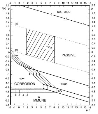
You need just a fraction of a volt negative potential and there will be some hydrogen
evolution from the etching , as the Ti frees that H2 from the acid . The etching is the corrosion region on the diagram .
But as you gradually increase the negative voltage on the etched Ti , the hydrogen evolution should slow greatly ,
and even stop completely (make a note of this voltage)
As you continue to increase the negative voltage then the hydrogen evolution will at a point gradually increase again .
At that point you have gone beyond the adsorption rate
and should back the voltage back down , but keep it above the voltage where you noted the disappearance
of the H2 earlier . That should put you in the voltage region where the Ti is actively hydriding ( immune on the diagram). A hot solution will
possibly favor the hydriding , 80C may even be required , I'll have to check this . IIRC there is a window condition that is required .
Your actual voltage reading will likely be different , and you want good electrode spacing so it will be higher . Just use the diagram to understand
the relationship of the voltages
you are noting and what they mean in your own cell according to what you are observing .
[Edited on 30-11-2007 by Rosco Bodine]
|
|
|
Xenoid
National Hazard
Posts: 775
Registered: 14-6-2007
Location: Springs Junction, New Zealand
Member Is Offline
Mood: Comfortably Numb
|
|
Hmmmm... But when I passivated the Ti rod in the cobalt sulphate and it developed the pretty blue coat, I then returned it to the acid for
"cathodisation" and the blue oxide layer disappeared very quickly. Surely this would suggest I was in the "corrosion" zone, if the thick "plated"
oxide layer was removed, the normal passivated layer wouldn't have stood much of a chance!
Edit: That "corrosion" zone is actually quite large. BTW what are the 4 "contour" lines surrounding it, labelled 0, -2, -4, -6 or are they 0, .2, .4,
.6 can't quite make it out.
Regards, Xenoid
[Edited on 30-11-2007 by Xenoid]
|
|
|
Rosco Bodine
Banned
Posts: 6370
Registered: 29-9-2004
Member Is Offline
Mood: analytical
|
|
You have to remember that the passivation layer on Ti
is conductive in the cathode configuration , so the reduction of another oxide is irrelevant as an indicator as to what is beneath .
I have a figure for hydride formation on Ti alloy 6Al 4V
at room temperature in 1N H2SO4 (~5% H2SO4) ,
current density
50 mA/cm2 100 uM depth at 12 hours , 150@16 , 230@24
no further depth development for longer times .
from US5178694
Evidently room temperature is fine for the hydriding ,
it may be the etch phase that required the heated bath
I was thinking I remembered reading about .
I read another bit somewhere else maybe an MSDS that said at ordinary temperature the titanium hydride is quite stable .
It requires chemical attack or significant heating to decompose it . The hydriding is actually used as a surface hardening treatment , something like
a case hardening for titanium .
Edit:
Something Wonderful !
It appears that the TiH2 is itself the conductive boundary
layer . The conductivity of TiH2 is little different from the metallic Ti .
http://www.sciencedirect.com/science?_ob=ArticleURL&_udi...
[Edited on 30-11-2007 by Rosco Bodine]
|
|
|
jpsmith123
National Hazard
Posts: 764
Registered: 24-6-2005
Member Is Offline
Mood: No Mood
|
|
@Dann2: IIRC, Patent #US3399966 implies some non-stoichiometric compound or mixture.
Patent #6001225 is ambiguous. The inventor mentions Co3O4, but doesn't back it up with any data...nor does he even say to what temperature the cobalt
nitrate coated substrate was baked.
The paper I uploaded regarding a plasma deposited coating started with a precursor of Co3O4, but claimed that it gets converted to CoO in the process.
Lastly, patent #4222842, which again involves baking Co(NO3)2, says the result is "a composition close to Co3O4..."
I tried, but was unable to find out much information about the thermal decomposition of Co(NO3)2 in air.
I did find an abstract of a paper that studied the thermal decomposition of cobalt acetate:
J. Mater. Chem., 1991, 1, 461 - 468, DOI: 10.1039/JM9910100461
Thermal decomposition of cobalt(II) acetate tetrahydrate studied with time-resolved neutron diffraction and thermogravimetric analysis
Robin W. Grimes and Andrew N. Fitch
The thermal decomposition of cobalt acetate tetrahydrate has been studied using time-resolved powder neutron diffraction. By using selectively
deuterated samples, the loss of water or the breakdown of the acetate group can be identified by following the decrease in the incoherent background
of the diffraction pattern as the hydrogen atoms are lost. The results suggest that by 150 °C dehydration is complete and a glass-like phase is
formed. Crystallization of this anhydrous acetate occurs at 200 °C. Further heating initiates a two-stage decomposition of the anhydrous acetate
terminated by the formation between 275–310 °C of a tetrahedrally co-ordinated cubic zinc blende form of CoO. This transforms at 310 °C to a
rock-salt structure. The neutron diffraction data have been complemented by thermogravimetric and chemical analyses from which we have been able to
propose some possible intermediate decomposition products and suggest an explanation for the formation of the unusual zinc blende form of CoO.
@Xenoid, when I tried plating the graphite I didn't see any gas bubbles form on the graphite (although it's difficult to see clearly because the
solution is so dark), so I assumed that the current was delivering product to where it was supposed to go.
As far as the hydriding step is concerned, I ran mine at 50 to 100 mA/cm^2 for over an hour. As I recall, there was a perceptible change in the color
of the Ti after the process...it became slightly darker.
I then put it immediately into the CoSO4 and it plated with no problem.
|
|
|
Rosco Bodine
Banned
Posts: 6370
Registered: 29-9-2004
Member Is Offline
Mood: analytical
|
|
The Dow patents which described investigation of cobalt and substituted bimetal cobalt spinels , even some trimetal variants , become even more
interesting in regards to application to a hydrided Ti substrate .
I think in a reply back then to garage chemist who was on
"Ruthenium road" I suggested that a baked cobalt on a hydrided substrate might be the best way to go as an alternative , and that idea looks even
better now , knowing more about the TiH2 .
The color of the TiH2 should be a duller darker gray as opposed to the light metallic gray silvery color of the
unhydrided Ti . Since the depth of the TiH2 layer can be
controlled by the time allowed at a known current density ,
then the reaction completeness can be discovered by trial and error with what particular chemical and/or baking treatment is applied after hydriding .
It can be discovered
what thickness of TiH2 provides the most conductive interface after it is decomposed by subsequent reaction .
Any of the coating schemes applicable to Ti should work
and likely work even better applied to the TiH2 . The thickness of the TiH2 layer which matches up with the subsequent treatment may or may not be
critical as a variable .
I have not found any reference as to whether or not the
junction of the TiH2 with the Ti is a rectifying junction or
not . But it would seem entirely possible that it could be
rectifying in the same direction polarity as is the anodizing
layer . This could account for and explain Xenoids observation that the hydrided substrate "passivated" immediately , if the TiH2 more precisely
"immuned" layer
was behaving in the same way as a passivation layer .
If that is what occurred then it may be required to subject the "immuned" Ti to some chemical or baking reaction to
reverse the "pseudo-passivation" , although this should
be much easier than the doping schemes as would usually
apply to an actual passivation layer . Almost any reactive material which would decompose the TiH2 and leave a blanketing and adherent and conductive
reaction product would be effective in producing a conductive interface , in
a similar but reversed scheme as is Ruthenium useful
for rendering a TiO2 layer conductive by forming a solid solution .
BTW , TiH2 is stable enough that it is used in micron sized powder form mixed with KClO4 as a flash powder in
pyrotechnics claimed to have excellent storage stability
and static and thermal insensitivity to unintended ignition .
Knowing that the TiH2 is that stable , a pretty minimal thickness of the TiH2 may be best if a mildly reactive non-baked coating is to be applied .
And it may not take much
more of a thickness of the TiH2 even for the baked and more reactive coatings .
[Edited on 30-11-2007 by Rosco Bodine]
|
|
|
Xenoid
National Hazard
Posts: 775
Registered: 14-6-2007
Location: Springs Junction, New Zealand
Member Is Offline
Mood: Comfortably Numb
|
|
| Quote: | Originally posted by Rosco Bodine
The color of the TiH2 should be a duller darker gray as opposed to the light metallic gray silvery color of the
unhydrided Ti .
This could account for and explain Xenoids observation that the hydrided substrate "passivated" immediately , if the TiH2 more precisely "immuned"
layer
was behaving in the same way as a passivation layer .
|
If the hydrided layer is a darker grey, then I never achieved a hydrided layer. Despite varying the conditions the treated surface remained the
silvery light metallic grey!
Regards, Xenoid
|
|
|
| Pages:
1
..
27
28
29
30
31
..
47 |


