| Pages:
1
..
30
31
32
33
34
..
47 |
dann2
International Hazard

Posts: 1523
Registered: 31-1-2007
Member Is Offline
Mood: No Mood
|
|
Hello Folks,
| Quote: | Originally posted by tentacles
I need to make more, but I'm out of calcium nitrate.
hashashan: Did your anodes end up curling like mine did? Interestingly, the curved sections didn't crack, I wonder if they are from the compression
stress, or if they are from the NaF doping. I can't wait to get home and silver/copper plate this thing, and pump chunky amps into it.
[Edited on 4-1-2008 by tentacles] |
The shimmering effect is a sight to behold. It looks like very fine blue/black velvet.
If you are going to plate more from the same tank you need Lead Carbonate or Oxide or some such to neutralize the formed Nitric acid and add more Lead
Ion. Perphaps you are making Carbonate or Oxide with the Ca Nitrate.
Then again fresh new tanks ALWAYS seem to give better coats. Products build up in the plating tank that seem to interfere with plating. Nitrites being
one.
I have seen massive anodes from the patents or somewhere which used an Iron substrate pipe. The funny thing is that they plated the Lead Dioxide on
the inside curve. Perhaps this 'inner curve plating' helped reduce or counteract the stress in the Lead Dioxide.
Perhaps if one were to bend the Ti before plating and plate on the inside curve it might help to give more reliable anodes.
Call it the 'Hashashan method modified by curve' (or some such) 
Dann2
|
|
|
chloric1
International Hazard
Posts: 1070
Registered: 8-10-2003
Location: GroupVII of the periodic table
Member Is Offline
Mood: Stoichiometrically Balanced
|
|
Better yet, just get on ebay becuase buying titanium anywhere else I think is a rippoff. I regularly see titanium tubing. It just a matter of
getting the right diameter. Cut a slit lengthwise and open slightly then apply a resist on the outside. You are ready to plate.
Fellow molecular manipulator
|
|
|
dann2
International Hazard
Posts: 1523
Registered: 31-1-2007
Member Is Offline
Mood: No Mood
|
|
Hello,
When plating on inside curve you may get less nodules etc at the edges too. (Guessing).
Dann2
|
|
|
Twospoons
International Hazard
Posts: 1282
Registered: 26-7-2004
Location: Middle Earth
Member Is Offline
Mood: A trace of hope...
|
|
Funny, I've often thought plating the inside of a pipe would be better. So many refs to stressed deposits cracking implies (to me) material under
tension - ie outer layers too "small". It seems to me that plating inside a curve would reduce this tension, maybe even put the PbO2 under
compression - which would be fantastic for mechanical strength. Just like pre-stressed concrete!
Helicopter: "helico" -> spiral, "pter" -> with wings
|
|
|
dann2
International Hazard
Posts: 1523
Registered: 31-1-2007
Member Is Offline
Mood: No Mood
|
|
Hello,
There is a bit of reading regarding bending and stress in US Pat. 4064035 below.
I cannot find the article/patent that described growing massive anode on the inside of an Iron (O no ) pipe. Anyone know where/what it is?
Beta LD is what we want on the outside of anodes. Alpha has better adherence to stuff. This is irrevelent with the Scotch cloth anodes. Alpha is
usually deposited from Alkali baths (Tartarate, Plumbite) Beta from Lead Nitrate bath.
RongPeng has said that Alpha LD comes from a Nitrate bath when current density is high (70mA per cm squared) and Beta when current denisty is lower
(40mA and less).
Perhpas you could deposit alternative Alpha:Beta etc by varing current density. Just a guess. The Apha made this way may not have similar stress (or
lack of stress) as per the Alpha coming from an Alkali bath. (as in the patent.)
Two baths = lot of 'hassle'.
@TwoSpoons
This is a good idea. The original 'inside job' (using an Iron pipe) was for massive anodes. The pipe was cut upon and LD removed. They were called
"pot core" anodes (as far as I can remember) for some reason or other.
If you were to leave the LD in place in the pipe that would surely be a sturdy set up. The pipe in this case would have to be a DTO'ed (or some such)
pipe, or perhaps a half pipe. (semi circle).
Now a Ti rod/pipe down the middle for cathode.................
Nitrites in tank: See US 2994649 where they add Hydrogen Peroxide to eliminate.
Dann2
[Edited on 8-1-2008 by dann2]
[Edited on 8-1-2008 by dann2]
Attachment: US 4064035 Alpha + Beta + Massive.mht (57kB)
This file has been downloaded 1088 times
|
|
|
hashashan
Hazard to Others
Posts: 255
Registered: 10-10-2006
Member Is Offline
Mood: No Mood
|
|
Guys really I think that a hard substrate will eliminate the bending, it worked for me.
|
|
|
12AX7
Post Harlot
Posts: 4803
Registered: 8-3-2005
Location: oscillating
Member Is Offline
Mood: informative
|
|
When I tried plating PbO2 onto graphite (in an acetate solution), I got spots of curly, flaking PbO2.
Tim
|
|
|
tentacles
Hazard to Others
Posts: 191
Registered: 11-11-2007
Member Is Offline
Mood: No Mood
|
|
hashashan; The ti strip I used is 1mm thick - it did not bend, the PbO2 plating curled during the process. I'll never know how this one would do as I
broke it while trying to attach the electrical conection. The NaF doped PbO2 does not seem to take silver plating well.
|
|
|
hashashan
Hazard to Others
Posts: 255
Registered: 10-10-2006
Member Is Offline
Mood: No Mood
|
|
very weired. You did evry thing I did and you got bending.
|
|
|
hashashan
Hazard to Others
Posts: 255
Registered: 10-10-2006
Member Is Offline
Mood: No Mood
|
|
Finally I managed to rewire my PSU (after so many were scorched and sent to the trash) now I can set it to any voltage in this range 2-6 or 8.5-13
the 6-8.5 Is missing (just couldn't remove the overvoltage protection) and that would be the most convenient voltage ... well anyway back to our
business, launched my anode into a chlorate cell first hopefully to continue to perchlorate on the fly. Now it is pumping 5.5 amps at 6 volts, tried
it at 8.5 and the current is 12 amps(to risky for my shitty PSU.. well have to wait for one week to see results...
|
|
|
dann2
International Hazard
Posts: 1523
Registered: 31-1-2007
Member Is Offline
Mood: No Mood
|
|
Hello,
Regarding PSU from computers. It would be better to obtain/attach a constant current circuit to what ever voltage output would be fairly close to the
max. output voltage you may need. This would suit plating/electrochemical cells.
Perhaps some of you guys (hint hint) would design a max. simplicity circuit that simply attaches to some voltage combination of the PC PSU and shove
out a programmed current. Tim did a good circuit (I did not build) but the constant current modules are specific to that circuit. If a more 'stand
alone' constant current circuit could be had it would be very useful.
Anyhows. I attempted to coat my DTO anode (this DTO anode has been sitting on my bench for the last 1.5 months) with Alpha LD, from a Lead Plumbate
bath.
Litharge was dissolved in 2N NaOH solution.
I cannot get this (damm) bath to plate anything. It will not plate DTO. Tried freshly etched Ti and it passivated immediately. A brown loose coating
of LD went onto the DTO but it does not increase in thickness and rubbs off.
I tried a piece of Graphite that had been previously coated with Beta Lead Dioxide (from Lead Nitrate bath) but no Alpha coating formed.
I tried changing the NaOH to a different hardware store variety (99-100%) but it made no difference. The litharge is Technical grade. The water is
clean rain water.
Lots of Lead appears on cathode.
There is lots of gassing on the anode and cathode.
Would this type of bath be very sensitive to contaminents?
Don't have a clue why it will not work.
It is mentioned in lots of patents.
I am going to try a Lead Tartarate bath next.
Dann2
[Edited on 14-1-2008 by dann2]
[Edited on 14-1-2008 by dann2]
|
|
|
12AX7
Post Harlot
Posts: 4803
Registered: 8-3-2005
Location: oscillating
Member Is Offline
Mood: informative
|
|
Isn't plumbate more soluble and acidic than plumbite? Why would PbO2 deposit in such a bath?
Tim
|
|
|
dann2
International Hazard
Posts: 1523
Registered: 31-1-2007
Member Is Offline
Mood: No Mood
|
|
Hello,
| Quote: | Originally posted by 12AX7
Isn't plumbate more soluble and acidic than plumbite? Why would PbO2 deposit in such a bath?
Tim |
I might as well be blunt/honest:
I have no idea!
From a patent: (lots of patents use this bath to deposit Alpha LD).
__________________________________________
A 4 square inch area of this titanium plate was then coated with a layer of lead dioxide by electroplating for 20 minutes at room temperature at 0.3
ampere per square inch (46.5 milliamperes per square centimeter) in a sodium plumbate plating solution containing NaOH (80 grams per liter) and PbO
(30 grams per liter).
___________________________________________-
Dann2
|
|
|
chloric1
International Hazard
Posts: 1070
Registered: 8-10-2003
Location: GroupVII of the periodic table
Member Is Offline
Mood: Stoichiometrically Balanced
|
|
| Quote: | Originally posted by 12AX7
Isn't plumbate more soluble and acidic than plumbite? Why would PbO2 deposit in such a bath?
Tim |
To be honest, I thought tartrate was REQUIRED in order to get alpha PbO2. Never heard of a working plumbite or plumbate PbO2 bath. THere is no
reason why such a bath would deposit anything BUT lead metal on the cathode. The tartrate bath prevents the distribution of free Pb++ running around
naked in the electrolyte doing God knows what
Alkaline Lead EDTA would be a fun experiment too. 
Fellow molecular manipulator
|
|
|
dann2
International Hazard
Posts: 1523
Registered: 31-1-2007
Member Is Offline
Mood: No Mood
|
|
Hello,
I will certainly have to do something about that streaking Lead ions.
Heaps of patents have given the straight NaOH + PbO bath above for plating Alpha.
Some eg's
http://www.geocities.com/CapeCanaveral/Campus/5361/chlorate/...
Anyhow I cannot get it to work so will move to Tartarate.
Dann2
|
|
|
Rosco Bodine
Banned
Posts: 6370
Registered: 29-9-2004
Member Is Offline
Mood: analytical
|
|
| Quote: | Originally posted by dann2
Hello,
Regarding PSU from computers. It would be better to obtain/attach a constant current circuit to what ever voltage output would be fairly close to the
max. output voltage you may need. This would suit plating/electrochemical cells.
Perhaps some of you guys (hint hint) would design a max. simplicity circuit that simply attaches to some voltage combination of the PC PSU and shove
out a programmed current. Tim did a good circuit (I did not build) but the constant current modules are specific to that circuit. If a more 'stand
alone' constant current circuit could be had it would be very useful.
Dann2 |
Actually DerAlte and I were back and forth for a couple of months via U2U's in an effort to pin down what should work , and I started to post the
product of that exchange as a Christmas present especially for 12AX7 , as an example of some engineering which might have some chance of working and
working efficiently . With all the excitement
over the cobalt spinel interface that Xenoid stirred up with
his heat gun powered anode hot potato cannon .....
I almost forgot about the constant current output module which was so long being sorted out . Besides , school was out for Christmas break and I felt
it would probably be better to wait until the holiday was over , resuming the learning experience and all when it's time for classes to begin again

Anyway it's damn well not so simple as one might hope .
I even got in touch with tech support at one of the world's leading technology vendors for this sort of thing , trying to
get some disclosure concerning the one and only one
lab testing which has been done paralleling this module ,
and they promptly "lawyered up" with the sorry it's proprietary black box technology kind of reply that told
me less than I already knew before inquiring , mainly
just to confirm that their "unpublished solution" was
probably just about identical to what DerAlte and I already
sorted out and figured out as being likely .
The constant current output module is complicated enough by itself before being plugged back into that earlier control stage which was designed before
and did check out on paper as valid AFAIK . And I haven't redrawn the schematic with the finalized design for the *pair* of paralleled output
modules as I have to rescale the entire drawing for it to fit and have been thoroughly occupied otherwise too much to get to that finishing of the
whole schematic .
Looking at the complexity of the whole thing I figure it's good
technically... but it's not really a "basic" electronics sort of project but is a seriously high current industrial duty kind of chip controlled power
supply which would take some skill and balls to build .
However , I will post it back in the other PS thread .
And I do have the circuit modeled in LT Spice if anyone
wants to look at the pulse response simulations ect .
The sims indicate it will probably work okay .
[Edited on 14-1-2008 by Rosco Bodine]
|
|
|
Xenoid
National Hazard
Posts: 775
Registered: 14-6-2007
Location: Springs Junction, New Zealand
Member Is Offline
Mood: Comfortably Numb
|
|
| Quote: | Originally posted by dann2
Regarding PSU from computers. It would be better to obtain/attach a constant current circuit to what ever voltage output would be fairly close to the
max. output voltage you may need. This would suit plating/electrochemical cells.
Perhaps some of you guys (hint hint) would design a max. simplicity circuit that simply attaches to some voltage combination of the PC PSU and shove
out a programmed current. Tim did a good circuit (I did not build) but the constant current modules are specific to that circuit. If a more 'stand
alone' constant current circuit could be had it would be very useful.
|
Dann2, whilst a constant current power supply is very useful in a plating situation, I don't really think it's called for with amateur (per)chlorate
cells. For electroplating purposes just get a laboratory power supply with constant current/voltage, these are pretty cheap these days, and
indispensible for experimental electrochemistry. These are good for 3 - 4 amps which is all you need unless you are plating something huge.
I am currently running my "Big Bertha" chlorate cell almost totally unregulated ( variac + transformer) it's running at about 24 amps and only goes up
and down by 1 or 2 amps from day to day, I rarely touch the variac.
For cells, try using the simple circuit posted by Aqua_Fortis_100% on page 8 of the "KClO3 ......" thread;
http://www.4shared.com/file/32991572/7dcdf563/Regulador_0_a_...
I've tried this circuit and it works fine. It's just a simple current regulator attached to the +5 volts of a computer PSU. It uses a cheap power
transistor to control the current and only uses a handful of parts. I've picked up another two computer PSUs for a few dollars and I'm going to mount
a current control like this on each of them. Big heatsink on one side and control potentiometer on the front. It will save messing around getting just
the right high wattage resistor for current control.
|
|
|
tentacles
Hazard to Others
Posts: 191
Registered: 11-11-2007
Member Is Offline
Mood: No Mood
|
|
dann2: In belated response to your post at the top of the page; I use Ca(NO3)2 and CuSO4 to make Cu(NO3)2 and then add Pb metal to displace the
copper. It works quite well, though there remains a bit of copper in solution afterward - not a big problem since I'd add some anyways.
|
|
|
dann2
International Hazard
Posts: 1523
Registered: 31-1-2007
Member Is Offline
Mood: No Mood
|
|
Hello,
About the circuit that Aqua_Fortis_100%:
Is it a constant current output or constant voltage?
I have a lab power supply (current limited) It would be nice to have about 5 of them for all the plating testing etc.
The PC supply with constant current modude would be nice (I think).
A hugh complicated circuit is of NO USE WHAT SO EVER (just in case someone is thinking of posting one!!!)
@Tentacles Does it take long for the Pb to displace the Copper. Do you cut it up finely.
Dann2
|
|
|
Xenoid
National Hazard
Posts: 775
Registered: 14-6-2007
Location: Springs Junction, New Zealand
Member Is Offline
Mood: Comfortably Numb
|
|
| Quote: | Originally posted by dann2
About the circuit that Aqua_Fortis_100%:
Is it a constant current output or constant voltage?
|
No Dann2, it's not constant current, it utilises the constant voltage computer PSU, it just behaves like a variable resistor, and will get hot if you
have a lot of current flowing. The circuit is only 2 transistors, 2 resistors and a potentiometer, you can't get simpler than that! You can just
connect your (per)chlorate cell and dial up the current, you may need to adjust from time to time as the cell parameters change. It saves fiddling
with different value resistors to get the right current for individual cells.
|
|
|
Twospoons
International Hazard
Posts: 1282
Registered: 26-7-2004
Location: Middle Earth
Member Is Offline
Mood: A trace of hope...
|
|
You can get simpler if all you want is a bit of additional stability. Just add an ordinary lightbulb in series. As the current drops, the filament
cools a bit and its resistance drops, helping to prop the current up. By no means perfect, but very, very simple and cheap. And you can see at a
glance if the power has gone off!
Helicopter: "helico" -> spiral, "pter" -> with wings
|
|
|
tentacles
Hazard to Others
Posts: 191
Registered: 11-11-2007
Member Is Offline
Mood: No Mood
|
|
dann2: not long at all, especially if you take strips of Pb (I have a sheet of Pb roof flashing) and hang them from your beaker, and stir it with a
stir bar or something. I'd say 24 hours is probably sufficient - you could certainly go longer, and I have, but after some point it's diminishing
returns. I've found if you leave (excess) lead hanging/sitting in the solution for too long, the lead seems to start falling out of solution as
(Pb(OH)2 ?), whilst more lead metal dissolves. I haven't really bothered to see if this continues until all the lead metal is converted, but it's
certainly possible.
A second try at a massive PbO2 anode has bent the Ti strip in a slight curve - this time the Ti was pitted so the PbO2 seems to be sticking like a
bitch. I haven't tried to peel it off - I thought I'd plop it in a cell for a while and see if I can't get it to plate off as the Ti passivates.
|
|
|
dann2
International Hazard
Posts: 1523
Registered: 31-1-2007
Member Is Offline
Mood: No Mood
|
|
Hello,
Finally got around to coating the Magnetite-on-Ti anode.
It appears that Magnetie will take a coating of LD OK.
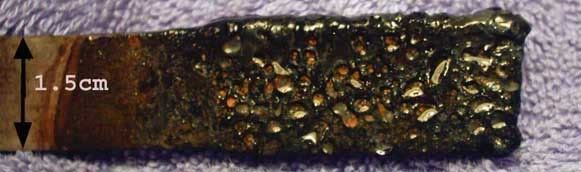
The photo was taken when anode was wet. The indends are caused by the bubbles when plating. I put on an Alpha then a Beta layer.
Testing to commence forthwith.
Did the beads/ceramic particles word well in the cells that you guys used to make your massive anodes?
Dann2
Or should I have said I coated a valve metal previously coated with a mono metal inverse spinel with Plumbous(ish) Oxide to achieve the best
ever......................
[Edited on 17-1-2008 by dann2]
|
|
|
Twospoons
International Hazard
Posts: 1282
Registered: 26-7-2004
Location: Middle Earth
Member Is Offline
Mood: A trace of hope...
|
|
Have you ever tried putting an aquarium bubbler beneath the anode while plating? That might be an effective way of removing bubbles from the anode
and agitating the bath at the same time.
Helicopter: "helico" -> spiral, "pter" -> with wings
|
|
|
tentacles
Hazard to Others
Posts: 191
Registered: 11-11-2007
Member Is Offline
Mood: No Mood
|
|
I found the silica grit just got caught in the fibers of the scotch brite, but on the exposed PbO2 it works pretty well. I did take some fairly high
res pics of the anode.. http://www.apcforum.net/files/DSCN6800.JPG
dann: I've never had bubble that big form on my anodes during plating but I usually keep the current density low - I like 15ma/cm2. Also, I ALWAYS
plate on a stirring hot plate (ensuring a controlled temp) with a 6cm stir bar going as fast as I can spin it.
I will try making a Ti/Co/DTO/PbO2 anode soon. I have more Ti on the way for to better experiment. I need more cathodes!
[Edited on 16-1-2008 by tentacles]
|
|
|
| Pages:
1
..
30
31
32
33
34
..
47 |


