| Pages:
1
2
3
4
5
6
..
9 |
Varmint
Hazard to Others

Posts: 264
Registered: 30-5-2013
Location: Near Atlanta, GA
Member Is Offline
Mood: No Mood
|
|
Usually the cap goes from pin 6 (threshold) + 2 (trigger) to ground (pin 1), using it tied to VCC (pin 8) obviously works, but operates on a different
slope than the "traditional configuration". Take a look at the link I provided, you are interested in the astable configuration.
As the frequency rises the whining naturally falls off simply because the motor isn't efficient as an audio transducer (yay!), it has too much mass.
Also, the attached mass and the associated flywheel effect tends to smooth things out as well, so the reduction in sound level is entirely expected.
So, you can keep reducing the size of the cap, knowing it also increases the minimum frequency (speed). So far as your frequency control pot you'll
want to make the total resistance the same or better yet larger in order that while you reduce the cap for higher frequency, the low end setting still
offers a workably slow speed.
There are many websites discussing the 555, some will provide a calculator where you input the minimum and maximum desired frequency, and it will tell
you the ideal values for the pot, resistor, and cap in astable operation.
I'm concerned you say the pot range is reduced, but once you configure it for more traditional astable wiring, then it will make more sense to try and
troubleshoot.
|
|
|
Magpie
lab constructor
Posts: 5939
Registered: 1-11-2003
Location: USA
Member Is Offline
Mood: Chemistry: the subtle science.
|
|
More good news: by replacing the 22µF cap with a 10µF cap the maximum speed has been increased from 100 to 200 rpm! The speed range is continuous
from 44 to 200 rpm. If it was any faster I would need a tachometer to measure it. Also the 2k pot span is good from full ccw to 90% of full cw.
I will take a look at the link you gave to calculate the resistors and capacitor values for the astable 555 condition. There's also a good
description of the 555 timer IC on Wikipedia.
I'm going to work on cutting off the gear on the shaft now. When the new coupler arrives I will make a movie on stirring salt at 200 rpm.
The single most important condition for a successful synthesis is good mixing - Nicodem
|
|
|
Magpie
lab constructor
Posts: 5939
Registered: 1-11-2003
Location: USA
Member Is Offline
Mood: Chemistry: the subtle science.
|
|
The gear came right off the motor shaft by making 2 longitudinal cuts with the dremel cut-off wheel. Thanks very much for this tip, Varmint.
I've been playing with the calculator for the astable oscillator circuit for the 555 found here:
http://home.cogeco.ca/~rpaisley4/LM555.html#3
With the cap set at 10µF and R2 set at 22Ω the following frequency and duty cycles result:
R1 = 690Ω
Hz = 197
duty cycle = 97.0%
speed = 59 RPM
R1 = 30Ω
Hz = 1950
duty cycle = 70.3%
speed = 585 RPM
The 59-585 rpm speed range could therefore be achieved by using a pot at R1 covering the range of 30-690Ω.
However, on the calculations page there is this statement:
"R1, R2 -- MINIMUM = 1K."
When values of 1K or greater are used sufficient frequency cannot be achieved. Eg, at R1=R2=1K the frequency is only 48Hz and the RPM 14. It just
gets worse as R1 and R2 are increased.
Therefore, I am hesitant to reconfigure to this more "normal" configuration.
Is this right, or am I missing something?
[Edited on 2-12-2014 by Magpie]
The single most important condition for a successful synthesis is good mixing - Nicodem
|
|
|
Varmint
Hazard to Others
Posts: 264
Registered: 30-5-2013
Location: Near Atlanta, GA
Member Is Offline
Mood: No Mood
|
|
Simply reduce the cap again! You probably needn't concern yourself with duty cycle, I expect the driver input is only looking for a rising or falling
edge.
Looks like you are about to nail this, don't forget to fine-tune the driver current reference pot, and higher RPM is waiting with an increase in
voltage to the driver when you get the clock input high enough frequency.
|
|
|
Magpie
lab constructor
Posts: 5939
Registered: 1-11-2003
Location: USA
Member Is Offline
Mood: Chemistry: the subtle science.
|
|
You are correct. The astable oscillator model gives 600 rpm when the cap is around 0.25µF and R1=R2=1000Ω. With R1=7500Ω the speed = 203 rpm.
I am going to reconfigure and try it with R1=R2=1000Ω. The only 0.22µF cap that my local store (RadioShack) has is a polyester film type (50WVDC).
Is this type OK? It has no polarity. The caps I have been using are electrolytic with polarity. If not, I will have to get one by mail order.
The single most important condition for a successful synthesis is good mixing - Nicodem
|
|
|
Varmint
Hazard to Others
Posts: 264
Registered: 30-5-2013
Location: Near Atlanta, GA
Member Is Offline
Mood: No Mood
|
|
Non-polar is perfect. Only reason electrolytics are polarized is the correct polarity creates an ultra-thin insulator between the two plates (foils)
which gives the comparatively large capacitance for the size. The art is always advancing, but at one time even the 0.22uF was pretty sizeable.
Other than that, a cap is a cap so far as the timing circuit goes.
Don't forget, there is no reason to limit the low speed to something higher than you'd like, you can of course get lower speeds by making the proper
resistor larger. There will come a point where capacitor leakage will limit the slowest attainable speed (while still having a respectable high end),
it's all a balancing act of sorts, but several decades are easily in reach.
|
|
|
Magpie
lab constructor
Posts: 5939
Registered: 1-11-2003
Location: USA
Member Is Offline
Mood: Chemistry: the subtle science.
|
|
Great. What I will try then is R1=10k, R2=1k, and C=0.22µF. This should give me 182 rpm.
The single most important condition for a successful synthesis is good mixing - Nicodem
|
|
|
Varmint
Hazard to Others
Posts: 264
Registered: 30-5-2013
Location: Near Atlanta, GA
Member Is Offline
Mood: No Mood
|
|
Try this:
Capacitor 0.033uF from pins 6+2 to Gnd. (Pin 1)
Fixed resistor 1K from 6+2 to pin 7.
10K from pin 7 to one end of a 1 Meg pot setup as a rheostat (wiper connected to one end), the other end of the pot to Vcc (Pin 8).
The pot minimum setting (max frequency) then should be around 3500Hz or 1050 RPM.
The pot max setting (lowest freq.) should be 35Hz or so, or about 10 RPM.
This gives you a very wide practical range with no more experimenting, and lets you focus on drive voltage and current pot settings to tune the actual
useful highest speed.
DAS
|
|
|
IrC
International Hazard
Posts: 2710
Registered: 7-3-2005
Location: Eureka
Member Is Offline
Mood: Discovering
|
|
Magpie just so you know the 1K is not absolute although I agree with the recent posts by others. The reason for not going too low for this value is
easy to see. Pin 7 is an open collector. It's purpose is to discharge the timing capacitor. If the value is too low pin 7 will try to drag the supply
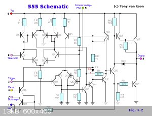
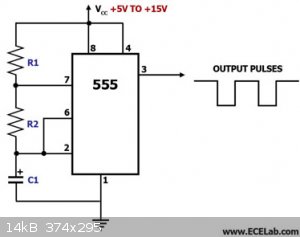
voltage down causing the internal transistor to fail. Look at these circuits I found somewhere online, they are useful in understanding both how the
IC works as well as how to use it in circuit design.
Reading my post again I should clarify what I mean by 'the 1K is not absolute'. It does not need to be 1K, but it does need to be large enough to
limit current flow from Vcc to ground through the internal transistor to a safe maximum. Meaning one also considers what voltage Vcc is. Another idea
if duty cycle is important (in circuit above it varies with the ratio of R1/R2 as you vary frequency) is to use a dual pot with the addition of the
current limiting resistor between pin 7 and Vcc when the pot is at its lowest value in rotation. A small bias to the ratio is created by this
resistor. If it was in a circuit where it is important the value could be halved using two resistors (say a pair of 470 ohm), one in series with R1
and the other with R2.
[Edited on 12-3-2014 by IrC]
"Science is the belief in the ignorance of the experts" Richard Feynman
|
|
|
Magpie
lab constructor
Posts: 5939
Registered: 1-11-2003
Location: USA
Member Is Offline
Mood: Chemistry: the subtle science.
|
|
I just finished the reconfigure and a successful test using the components I listed in my last post. I measured the rpm at 177 which compares well to
the predicted 182. Actually this is an educated guess as the spin rate is too high for my old eyes to follow with any accuracy.
I'm not planning on increasing the supply voltage from the currently available 12vdc. It is doing the job and I have incurred no cost in getting it
as it is salvage from my old Gateway PC.
[Edited on 3-12-2014 by Magpie]
The single most important condition for a successful synthesis is good mixing - Nicodem
|
|
|
Magpie
lab constructor
Posts: 5939
Registered: 1-11-2003
Location: USA
Member Is Offline
Mood: Chemistry: the subtle science.
|
|
Here are my assumptions for a final configuration:
Fix R2 at 1000Ω. Fix C at 0.22µF. Provide R1 as a 100k pot. This will provide 21 rpm at the low end. I'm going to assume that the R1 pot will
turndown to 1000Ω at the high end for 729 rpm. I don't envision needing a higher rpm than this. To comply with R1 minimum =1000Ω I might have to
put a stop on the pot wiper or add a fixed permanent resistance in series. I've been searching the Digi-Key website for pot specifications but they
don't seem to list the turndown ratio. I don't believe the pots go to 0 Ω, or do they? Let me know any concerns.
[Edited on 3-12-2014 by Magpie]
The single most important condition for a successful synthesis is good mixing - Nicodem
|
|
|
Varmint
Hazard to Others
Posts: 264
Registered: 30-5-2013
Location: Near Atlanta, GA
Member Is Offline
Mood: No Mood
|
|
Yes, pots can and do go down to zero (or at least into the single ohms or even less), which is why I suggested a fixed resistor in series in my
configuration.
|
|
|
Magpie
lab constructor
Posts: 5939
Registered: 1-11-2003
Location: USA
Member Is Offline
Mood: Chemistry: the subtle science.
|
|
I installed a 100k linear pot. In testing it with my ohm meter it gave a range of 1k-100k. It ran the stepper from 21 rpm to an rpm that by
eye/stopwatch was 218 rpm. By wiper travel (270°) and resistance measurement using the model it was 156 rpm. Beyond that the motor stopped. Full
wiper travel is 310°.
Is this limit a function of the supply voltage?
The single most important condition for a successful synthesis is good mixing - Nicodem
|
|
|
Varmint
Hazard to Others
Posts: 264
Registered: 30-5-2013
Location: Near Atlanta, GA
Member Is Offline
Mood: No Mood
|
|
I'd be tempted to say your 555 might be going flakey, do you have the Reset pin (4) tied to Vcc, and the Control pin (5) tied to Gnd through a 0.01uF
cap? If not, please do so, these pins can cause issues, especially in the non-ideal environment of a prototyping board.
The reason I'm not jumping on the supply voltage (being too low) right out of the gate is you are already near 4x the motor rated voltage, and half
the mfgrs torque test curve voltage, so I'd look for other issues first. If you can eliminate the 555 from being the source of bad signals, the next
option is to try and up the voltage and see what you get.
|
|
|
Magpie
lab constructor
Posts: 5939
Registered: 1-11-2003
Location: USA
Member Is Offline
Mood: Chemistry: the subtle science.
|
|
Quote: Originally posted by Varmint  | I'd be tempted to say your 555 might be going flakey, do you have the Reset pin (4) tied to Vcc, and the Control pin (5) tied to Gnd through a 0.01uF
cap? If not, please do so, these pins can cause issues, especially in the non-ideal environment of a prototyping board.
|
No, these pins are not terminated. Would a 0.022µF suffice?
The single most important condition for a successful synthesis is good mixing - Nicodem
|
|
|
Varmint
Hazard to Others
Posts: 264
Registered: 30-5-2013
Location: Near Atlanta, GA
Member Is Offline
Mood: No Mood
|
|
Yes, no problem.
|
|
|
Magpie
lab constructor
Posts: 5939
Registered: 1-11-2003
Location: USA
Member Is Offline
Mood: Chemistry: the subtle science.
|
|
Pins 4 & 5 were terminated and the circuit tested. This did not make any difference. The wiper still came to the same position for peak rpm (by
ear) just before motor stoppage.
I don't have any other vdc source.
The shaft coupler arrived today. I will test the mixer on a salt slurry at the new peak rpm tomorrow and post a video.
The single most important condition for a successful synthesis is good mixing - Nicodem
|
|
|
Magpie
lab constructor
Posts: 5939
Registered: 1-11-2003
Location: USA
Member Is Offline
Mood: Chemistry: the subtle science.
|
|
The assembly was tested on a salt slurry at peak rpm (~200) and performs well. But I need to reverse the present direction of rotation, ccw, to cw,
to prevent unscrewing the chuck. The present wiring is as follows:
Looking at the side of the motor, shaft down:
Left to right: yellow, skip one, red, blue, skip one, orange
Looking down on the driver with the little pot to the right:
pin 11: red
pin 12: yellow
pin 13: blue
pin 14: orange
I could experiment but thought it better to ask: how should I reorder the driver pin colors to reverse the direction?
The single most important condition for a successful synthesis is good mixing - Nicodem
|
|
|
Varmint
Hazard to Others
Posts: 264
Registered: 30-5-2013
Location: Near Atlanta, GA
Member Is Offline
Mood: No Mood
|
|
No need!
There is a pin on the driver which sets the direction, right now it is either pulled up (most likely by far), or pulled down, you simply need to
change that signal to accomplish reverse.
But, if you want to do it via motor leads, move blue and orange to 11 and 12, red and yellow to 13 and 14.
|
|
|
Magpie
lab constructor
Posts: 5939
Registered: 1-11-2003
Location: USA
Member Is Offline
Mood: Chemistry: the subtle science.
|
|
I can't seem to find that pin. Here's my driver. Please tell me the location of this pin.
http://www.ebay.com/itm/121427026317?_trksid=p2060778.m2749....
The single most important condition for a successful synthesis is good mixing - Nicodem
|
|
|
Varmint
Hazard to Others
Posts: 264
Registered: 30-5-2013
Location: Near Atlanta, GA
Member Is Offline
Mood: No Mood
|
|
OK, on one row of pins you have the 4 motor wires
On the other row of pins, you have your 555 output going to the 2nd pin of that row, (one pin in from the end). Direction is the first pin.
|
|
|
Magpie
lab constructor
Posts: 5939
Registered: 1-11-2003
Location: USA
Member Is Offline
Mood: Chemistry: the subtle science.
|
|
I don't think my driver has that switch. I switched the wires and it is rotating cw now. Thanks.
I'll make the video now. If I don't get it posted tonight I'll post it tomorrow morning.
The single most important condition for a successful synthesis is good mixing - Nicodem
|
|
|
Varmint
Hazard to Others
Posts: 264
Registered: 30-5-2013
Location: Near Atlanta, GA
Member Is Offline
Mood: No Mood
|
|
I went back and looked at the schematic on page 2 of this thread, and Diddi shows the pin to the right of the step pin tied to ground. This is the
direction pin.
If we were to number the pins based on that drawing, and treating the pinout just like an IC, pins 1 through 4 are open, 5 and 6 are tied to +5V, 7 is
the step input (clock output from 555), and pin 8 is shown as grounded, this is the wire you would remove on your proto board, which would have left
it pulled up by the resistor on the board, thereby changing direction.
I know the other way I tried to describe it was confusing, well, there's a reason for that. This hardware is in the public domain, no one has
"rights" to it, it can be copied freely, and produced in quantity by anyone who chooses to do so. Well, a lot of these vendors don't much care about
accuracy or standards, all they want is a device that will plug into a socket and take the place of a more expensive solution from the original
vendor, for much lower cost, and they can do this by providing no support of any kind. This driver happens to be a knockoff of the "Big Easy Driver"
I provided a link to, and is produced by a myriad of companies, another being Polulu.
Polulu's page is here, note the schematic at the bottom of the page. http://www.pololu.com/product/2128
DAS
|
|
|
Magpie
lab constructor
Posts: 5939
Registered: 1-11-2003
Location: USA
Member Is Offline
Mood: Chemistry: the subtle science.
|
|
OK, thanks for that explanation. I wondered how I was able to get this driver so cheaply. When you say "pull" a pin I didn't realize that meant
disconnect the pin. Now I know.
The video showing the mixer stirring a salt slurry at ~200 rpm is shown below. The slurry was made up of 3/4 cup of salt and 200 ml of water. Flask
size is 500 ml.
I consider this project to be complete now and very successful. I feel that this stirrer would meet 95% of the needs of the home chemist for overhead
stirring. I want to thank diddi and varmint for all the help given me. The mixer wouldn't exist without that help.
As always comments, suggestions, and questions are welcomed.
https://www.youtube.com/watch?v=G_A5uT7PpJE
The single most important condition for a successful synthesis is good mixing - Nicodem
|
|
|
Magpie
lab constructor
Posts: 5939
Registered: 1-11-2003
Location: USA
Member Is Offline
Mood: Chemistry: the subtle science.
|
|
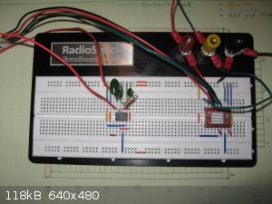
I recently consolidated the breadboard wiring for my stepper motor. This was done in preparation for transferring it to a perf board to make a
permanent soldered assembly. The consolidated wiring is shown in the photo below. When tested the motor did not operate after the consolidation. I
knew I had made some wiring mistakes but had corrected them. Assuming I had fried the 555 timer I replaced it with a new one. The motor now operates
but the range has been reduced to 48-100 rpm. Before the consolidation the range was 20-200 rpm.
I have checked the wiring many times over. Is there something else I might try to get my old rpm range back?
The single most important condition for a successful synthesis is good mixing - Nicodem
|
|
|
| Pages:
1
2
3
4
5
6
..
9 |


