| Pages:
1
..
4
5
6
7 |
12AX7
Post Harlot

Posts: 4803
Registered: 8-3-2005
Location: oscillating
Member Is Offline
Mood: informative
|
|
| Quote: | Originally posted by 7he3ngineer
...Ok Tim, we've all seen what your like at electronics, with your knowledge/ experience, what would be your preference, the custom ozone generator or
the NST.
What advantages would you see in building a custom circuit?
|
If I had an NST, none at all. If I didn't have one, I'd look for an inverter type NST, with the advantage that it's already higher frequency, which
apparently is advantageous here. I wouldn't build a custom circuit, there's no need.
| Quote: | Originally posted by Natures Natrium
Hmm, but the bridge rectifier is full wave, so shouldnt it be a steady stream of slightly rough DC? Oh, the bridge recitifier is not on the pcb,
maybe thats a possible misunderstanding? |
That doesn't matter, only that you're supplying some sort of DC to the circuit. And 600V is too much.
| Quote: | | Perhaps there is something fundamental I am missing here, but I dont understand how switching DC on/off to a step-up transformer constitutes a
half-wave... unless both the positive and negative sides of the DC need to have a turn at the primary of the transformer? Either I just stumbled onto
one of my mistakes or I have made yet another. |
Understanding inductors is prerequisite to using them!
The circuit is called half-wave because the power transistor only pulls down. The other half of the wave is provided by the inductance, which reaches
an unspecified peak voltage in your circuit. A bare inductor (as shown) will easily reach the transistor's breakdown voltage (a good reason to use an
avalanche-rated MOSFET rather than a more vulnerable IGBT) within a microsecond of it turning off (depending on capacitance and inductance). This
seems to be a reasonable model as your load is so far unspecified.
The overall point of an inductor is, the voltage on its terminals averages zero. You can pull it down for a while, but that builds current and when
you let go, the current needs to go somewhere and the voltage goes up.
If you just want HF HV, into an essentially capacitive load (I assume your corona generator is dielectric), use a chopper circuit. Two power
transistors, two windings and some resistors.
| Quote: | | 300V DC is kinda crappy though, surely there must be a way to get more mileage out of these 1200V rated parts. |
There isn't. Don't think of it as using at 1.2kV. 1.2kV is the *peak absolute* rating. This is something to avoid, not to use.
Tim
|
|
|
Natures Natrium
Hazard to Others
Posts: 163
Registered: 22-12-2004
Member Is Offline
Mood: No Mood
|
|
Alright, thanks again for the rapid reply. I did a web search for an inverter NST, didn't get anything. Most of the inverter schematics I could find
were specifically for producing 60hZ 110v AC from a 12v DC source. I found references to inverters which produce 20khz AC internally, but could find
no schematic which does the same. I found high current, high voltage transformers for welders, but the frequency there is usually around 1khz, plus
they are expensive.
Also, it somewhat shames me to admit I could not find anything regarding a workable chopper circuit. Everything I found regarding that subject was in
reference to signal processing.
So, I did some brainstorming and came up with a couple of ideas, and shot most of them down myself after some thought.
The only one which I think might work is placing the step-up transformer between two of the IBGTs aligned directionally, and have both IBGTs triggered
by the same signal from pin 3 of the 555. When the signal stops and the gates close, the coil is isolated from the circuit, and a capcitor (with
in-line resistors) with leads connected to both ends of the transformer absorb any kickback and feed it back into the system.
Perhaps I should have mentioned that the transformer I have in mind is not an autotransformer, but is rather an air-core with high K-coupling.
Speaking of high voltage transformers, I was able to locate a few online, although all of them are metal core and therefor probably not suitable for
the higher frequency applications. Since the DC voltage has dropped to 300v, I will need 100:1 step-up in order to achieve 30kv. 
Admittedly I am just picking at straws at this point. I saw an interesting diagram that used 4 transistors to route the energy back and forth across
the primary, but they didnt go into any detail on how the timing circuit for controlling those was set up.
For that matter, it did occur to me at one point that I might go 110v AC mains -> 160v DC -> 110v AC 20khz and feed that into my 10kV 30mA NST.
Might even go so far as take the 10kV and try to step it up via a 3:1 air core to get my 30kV-20khz-10mA. I have no idea how the insides of the NST
are setup, and therfor how it would react to high frequency current, however.
Meh, like I said just brainstorming and throwing out ideas. Back to the drawing board, for the moment.
thanks again,
-NN
\"The man who does not read good books has no advantage over the man who cannot read them.\" - Mark Twain (1835-1910)
|
|
|
12AX7
Post Harlot
Posts: 4803
Registered: 8-3-2005
Location: oscillating
Member Is Offline
Mood: informative
|
|
| Quote: | Originally posted by Natures Natrium
Also, it somewhat shames me to admit I could not find anything regarding a workable chopper circuit. Everything I found regarding that subject was in
reference to signal processing. |
Checking myself, finding a web reference seems rather akward. I guess you've got me, it's something that, anyone who knows anything about electronics
knows about, and as such says little about. Maybe it's the kind of thing found in books.
At any rate, it's a very simple self-excited push-pull oscillator circuit. Powerlabs has an example of a single-ended version:
http://www.powerlabs.org/flybackdriver.htm
You basically mirror this (so the windings are CT'd) and use two transistors.
Since the drive is symmetrical, the waveform is symmetrical, too. This makes sense for HV AC.
| Quote: | | The only one which I think might work is placing the step-up transformer between two of the IBGTs aligned directionally, and have both IBGTs triggered
by the same signal from pin 3 of the 555. |
So what, they both do the same thing, in series? Why? You can get the same effect with half the forward drop by using just one.
| Quote: | | Perhaps I should have mentioned that the transformer I have in mind is not an autotransformer, but is rather an air-core with high K-coupling.
|
Make that low-K coupling and you've got half a Tesla coil going. Since your load is capacitive, that's not that bad an idea.....
| Quote: | | Speaking of high voltage transformers, I was able to locate a few online, although all of them are metal core and therefor probably not suitable for
the higher frequency applications. |
Metal core == laminated iron? You want powdered iron or ferrite, which are used for roughly 1kHz to several MHz in various forms. A cored
transformer always performs better than an air-core unit.
| Quote: | | Since the DC voltage has dropped to 300v, I will need 100:1 step-up in order to achieve 30kv. |
So? That's 5000 turns from a 50 turn primary, or only 1000 from a 10 turn primary (you'll need a high frequency to keep currents reasonable from such
a supply voltage though). Consider yourself lucky, that's quite modest for thirty fucking thousand volts. 
| Quote: | | Admittedly I am just picking at straws at this point. I saw an interesting diagram that used 4 transistors to route the energy back and forth across
the primary, but they didnt go into any detail on how the timing circuit for controlling those was set up. |
H bridge, a.k.a. full bridge. You can figure it out easily enough yourself: clearly, opposing transistors must be activated, since only one at a time
or a top or bottom pair does nothing, while vertical pairs would short out the supply. On closer inspection, you also get "twice" the supply voltage
out, because the load is ran in both directions.
There are three fundamental switching supply topologies: buck, flyback/boost and forward converters.
Buck converters are good for reducing a voltage. You see these on your computer's motherboard, supplying a little over a volt at maybe 30+ amperes to
the processor core, efficiently converting from a 5V, 10A supply. Buck converters don't supply isolated voltages. For your purpose, this isn't very
interesting.
Flyback/boost converters are the first type which can be isolated. As such, they can also produce voltages of any ratio to the supply, by using a
transformer. What's more, because the voltage is derived from the inductive flyback energy, it's determined by current draw and pulse width, allowing
easy throttling, inherently current limited operation and quickly responding voltage regulation. Because of transformer action and the potential for
additional voltage multiplication (due to the flyback pulse), this is perhaps the most interesting to you.
Forward converters are the most versatile in terms of power. In all likelihood, your computer is supplied by a half bridge forward converter circuit.
Forward converters need more magnetics (although sadly the extra part is often omitted!), but can be varied cleanly and effectively with PWM and
provides stable output voltages, even without active circuitry. A forward converter is essentially an HF oscillator driving a transformer which has a
rectifier attached. Current is drawn during both halves of the cycle (it is full-wave). (Forward converters can be built in half-wave form as well,
but at the sort of power levels they would be used (under 100W), they have little advantage over flyback converters. Incidentially, by now you should
be able to guess why a flyback converter must be half-wave.) As a full wave HF source, this topology may be the most interesting to your application,
as the secondary can be resonant-tuned with the capacitive load, reducing reactive losses.
| Quote: | | For that matter, it did occur to me at one point that I might go 110v AC mains -> 160v DC -> 110v AC 20khz and feed that into my 10kV 30mA NST.
|
Not quite. You may get a nice hot chunk of steel though. The laminated iron core in your transformer will pick up most of that energy by hysteresis
and eddy current losses. Here's a strip of similar transformer iron exposed to similar magnetism:

Tim
[Edited on 4-26-2008 by 12AX7]
|
|
|
Twospoons
International Hazard
Posts: 1282
Registered: 26-7-2004
Location: Middle Earth
Member Is Offline
Mood: A trace of hope...
|
|
It doesn't get much simpler than this:
Simple High voltage generator
Two transistors, some wire, and an old TV LOPT (line output transformer). Should be able to get the bits for under $20.
I've built one, and it works a treat for 30kV or so at around 25kHz. Great for doing plasma globe experiments, lighting up fluoro tubes remotely etc.
Loads of fun.
Helicopter: "helico" -> spiral, "pter" -> with wings
|
|
|
12AX7
Post Harlot
Posts: 4803
Registered: 8-3-2005
Location: oscillating
Member Is Offline
Mood: informative
|
|
That's the one.
Goldwasser, shoulda known! 
Tim
|
|
|
Natures Natrium
Hazard to Others
Posts: 163
Registered: 22-12-2004
Member Is Offline
Mood: No Mood
|
|
Ah, I have seen that circuit floating around the net for some time, and the single transistor version is supposed to be an easier though less
efficient (burns out the single transistor easier) design.
There are a couple of points, in regards to adapting this design to my purpose, that I am unsure of.
At first glance I assumed the two 5-turn sections of the primary were turned on alternately, but on actually looking at the schematic it appears that
both transistors are turned on near simultaneously, which would generate different (opposing?) fields on the primary. Of what possible advantage is
this versus a single transistor, non-centertapped design?
The other thing I am unsure of, and this is only applicable if the two sections of primary are supposed to alternate, is how one would derive two
opposing signals from a single signal source.
You may be right about using a lower K style transformer to power what is essentially an ultra-low efficiency (lots of corona bleed) high voltage
capacitor. I honestly don't know which would be more effective, but one thing does occur to me. Are not low-K transformers much more efficient when
there is resonance between the primary and secondary (thus requiring specific frequencies for decent efficiency and not suitable for this app)?
Also, having browsed many many tesla sites, and understanding well what it means to have the primary and secondary in resonance, there is still
something I have never quite grasped. Over and over again, especially in flyback designs, I have heard how putting the transformer in resonance
results in "enormous voltage gain". I cant grasp that concept intellectually. It seems to me that putting them in resonance, getting maximum
efficiency out of the magnetic fields, would result in current gain, not voltage. Is the voltage not almost exclusively determined by the turn ratio
of the transformer? Never really understood that.
Thanks again for the help. I am working on a single transistor redesign, which I wont hesitate to set aside if there are decent benefits to the
two-transistor set-up.
EDIT: Also, the red-hot chunk of iron being heated by magnetism is awesome. :-)
Sincerely,
-NN
[Edited on by Natures Natrium]
\"The man who does not read good books has no advantage over the man who cannot read them.\" - Mark Twain (1835-1910)
|
|
|
12AX7
Post Harlot
Posts: 4803
Registered: 8-3-2005
Location: oscillating
Member Is Offline
Mood: informative
|
|
| Quote: | Originally posted by Natures Natrium
At first glance I assumed the two 5-turn sections of the primary were turned on alternately, but on actually looking at the schematic it appears that
both transistors are turned on near simultaneously, which would generate different (opposing?) fields on the primary. |
No! They are alternate. If they were simultaneous (and the windings inverse), it would be operationally identical to putting two windings in
parallel, two transistors in parallel, etc., and you would have the single transistor circuit trivially. A tapped winding is ALWAYS in the same
direction throughout (otherwise it wouldn't be a tap!), so the transistors operate alternately and this is a push-pull circuit.
| Quote: | | You may be right about using a lower K style transformer to power what is essentially an ultra-low efficiency (lots of corona bleed) high voltage
capacitor. I honestly don't know which would be more effective, but one thing does occur to me. Are not low-K transformers much more efficient when
there is resonance between the primary and secondary (thus requiring specific frequencies for decent efficiency and not suitable for this app)?
|
Resonance means reactances cancel in each winding. If you want the primary tuned, you can do that; it doesn't need to be, of course then you need to
deal with whatever reactance it does have. Inductive reactance usually isn't a bad thing, as transistors prefer switching into a "springy" inductance
than a hard capacitance. Freewheeling diodes are often employed to clamp the flyback energy, recycling the energy absorbed by the reactance.
| Quote: | | Also, having browsed many many tesla sites, and understanding well what it means to have the primary and secondary in resonance, there is still
something I have never quite grasped. Over and over again, especially in flyback designs, I have heard how putting the transformer in resonance
results in "enormous voltage gain". I cant grasp that concept intellectually. It seems to me that putting them in resonance, getting maximum
efficiency out of the magnetic fields, would result in current gain, not voltage. Is the voltage not almost exclusively determined by the turn ratio
of the transformer? Never really understood that. |
Well with k < 1, the turns ratio isn't, now, is it? The model of a low-k transformer looks more like a perfect transformer with a series inductor,
the mutual inductance. By bringing both sides into resonance, the mutual inductance can be series-resonant with the transformer's capacitances,
thereby reaching a maxima of voltage.
Tim
|
|
|
Natures Natrium
Hazard to Others
Posts: 163
Registered: 22-12-2004
Member Is Offline
Mood: No Mood
|
|
*Click!*
Oooooh, now I get the whole meaning of push-pull. The rush of enlightenment combined with the shame of it having taken so long has produced a neutral
state.
Anyways, I still cant figure a way to operate both transistors alternately from a single 555. Any clues, hints, ideas, links, etc?
thanks,
-NN
\"The man who does not read good books has no advantage over the man who cannot read them.\" - Mark Twain (1835-1910)
|
|
|
12AX7
Post Harlot
Posts: 4803
Registered: 8-3-2005
Location: oscillating
Member Is Offline
Mood: informative
|
|
Plenty. Don't use a 555
Crack open a dead computer supply nearby and extract the TL494 (90% use a 494, the remainder use KA7500 -- same thing, SG3524, etc. All fundamentally
the same, look up datasheet for pinout), wire it up and go. This chip is designed for push-pull / bridge operation. Push-pull BJTs or MOSFETs are
the easiest, and a typical application is probably in the datasheet itself. Since you want AC rather than PWM, wire the control side so PWM is near
maximum (48% or so). If you want frequency control, you can use a pot for that, or you might add a feedback loop consisting of a voltage or current
or phase sensor and an error amp to control the frequency input. Alternately, a CD4060 PLL chip can be used for the same purpose, somewhat simpler.
I think the 4060 generates a plain square wave, so you may get shoot-through using it, which is the same problem as the 555's single square wave
output. I'd use a differential pair to generate inverse lines, then a pair of transistors to switch that into a regular logic-ey sort of voltage for
whatever is driven.
Tim
|
|
|
Natures Natrium
Hazard to Others
Posts: 163
Registered: 22-12-2004
Member Is Offline
Mood: No Mood
|
|
Hmm, since I got plenty of dead PC PS's kickin about, I'll have to look into this. (I had intended to use one as the 12V supply for timing circuit
anyhow.)
However, in the meantime, I found a good site which discusses some of the basics of 555 timers, with plenty of examples and built-in calculators.
This turned out to be a good thing because it pointed out a fatal mistake I had made some time ago, wherein I set up an excel spreadsheet with the
calculations for controlling the timer, and forgot to note that I had set it to display kilohertz, not hertz. Consequently with my 120pF SMC and
10kohm pots, the lowest attainable frequency would have been 363khZ.
Anyways, found the attachment at http://home.cogeco.ca/~rpaisley4/LM555.html#5
Good page, and using the built in calculators gave me a better idea of mathematical relationships involved. Better to keep R1 fairly small and use a
pot at R2 to adjust the frequency, thus resulting in a near 50% duty time regardless of output frequency.
Oh yes, the attachment. I am thinking that this circuit (I do actually have 2 identical 555s here), with the output from the 3s trigging my IBGTs A
and B, respectively. I suppose also that Timer B would need to be permanently on, until timer A turns off.
According to wikipedia here:
http://en.wikipedia.org/wiki/Flyback_converter
The estimated voltage feedback against the switch for a 960V 5:162 (1:32) turns transformer with a duty cycle of .5 (50% on, 50% off, which I am
working towards) is about 990V, or roughly 3.1% higher than the input voltages. However, it also says that doesnt include voltage gain from leakage
induction, and doesnt provide a way to calculate that. Couldnt find one either. Equation or link, maybe please? :-)
Also, I imagine with a two transistor push-pull setup, there is a lot less feed back since the circuit spends most of its time in the on-state. I was
also wondering if the two 5 turns are each counted as a separate primary as each respective transistor turns on, thus a 10-turn center tapped primary
and a 100 turn secondary is actually a 1:20 transformer, not a 1:10.
Part of the reason I am eager to go with a higher voltage feed to the primary is to reduce the number of turns needed on the secondary. I took apart
that old flyback I had, and salvaged the core out of it. Got pics of that I may post some time, but the point is that if I have to go with more than
~150 to ~200 turns I am going to have to start layering the turns. Im not even quite sure how thats supposed to work. Somehow wrapping from the
bottom up the first layer, then insulation, then continuing the wrap in the same direction (say, clockwise from an above perspective) but having each
consecutive wrap proceed back down the core doesnt seem right intuitively.
Hmm, found some tl494s on the interwebs, they are cheap, but most places have a minimum order. Will have to try to find them locally first. Havent
had much luck scrounging components off of old boards, I'd rather just get them new. This does look quite promising, although I haven't yet found a
representative schematic for controlling an inverter.
Well, Im done for the day. Thanks again for the assistance.
-NN

\"The man who does not read good books has no advantage over the man who cannot read them.\" - Mark Twain (1835-1910)
|
|
|
Twospoons
International Hazard
Posts: 1282
Registered: 26-7-2004
Location: Middle Earth
Member Is Offline
Mood: A trace of hope...
|
|
| Quote: | Originally posted by Natures Natrium
However, it also says that doesnt include voltage gain from leakage induction, and doesnt provide a way to calculate that. Couldnt find one either.
Equation or link, maybe please? :-)
|
There isn't one, as it depends on the build of the transformer, and how much current is in the primary. Voltage from leakage will rise until something
breaks, or the energy is all transferred to parasitic capacitance. Solution: either a fast zener diode or an R-C snubber across each primary. A
snubber will also help to prevent radio interference being generated.
| Quote: |
I was also wondering if the two 5 turns are each counted as a separate primary
|
Yes. Your primary is effectively 5 turns when calculating turns ratio.
| Quote: |
Somehow wrapping from the bottom up the first layer, then insulation, then continuing the wrap in the same direction (say, clockwise from an above
perspective) but having each consecutive wrap proceed back down the core doesnt seem right intuitively.
|
Don't worry, its exactly right, and how transformers are made industrially.
If you want to minimise leakage inductance, put 1/2 your secondary on first, insulate, put the primarys on (bifilar, maybe?), insulate, then the rest
of your secondary. Don't use vinyl tape for insulation, use mylar film or similar.
[Edited on 16-5-2008 by Twospoons]
Helicopter: "helico" -> spiral, "pter" -> with wings
|
|
|
12AX7
Post Harlot
Posts: 4803
Registered: 8-3-2005
Location: oscillating
Member Is Offline
Mood: informative
|
|
http://schmidt-walter.eit.h-da.de/smps_e/smps_e.html may come in handy.
A 50% duty cycle switching power to an inductor (with attached rectifier with an appropriate load) might give double the power supply's voltage, peak.
It can easily be over 10 times, especially for much higher duty or much lighter loading (the limiting factor is the amount of energy stored in the
inductor, and parasitic capacitance across the inductor which acts to reduce efficiency). This is why you must use transistors rated for
significantly more than your supply voltage.
Tim
|
|
|
Natures Natrium
Hazard to Others
Posts: 163
Registered: 22-12-2004
Member Is Offline
Mood: No Mood
|
|
Ok, thanks again for all the help guys.
Check out this pdf I found, from ON semi-conductor. Obviously they push thier parts in it, but it is a great overview and chock full of information
for the uninformed.
Of particular interest is is p. 94, wherein they present a half bridge design I haven't seen elsewhere, and which claims to have the benefit of not
exposing the transistors to greater than peak line voltage. Thus, they recommend 190v transistor for a 120v line-in application. I could probably
get away with 640v line-in, assuming that this benefit is not a direct result of the feedback on the IC controller.
Most of the switching power supply designs recommend 380v transistors for a 120v line-in application, which means 320v would probably need those 1200v
transistors I have.
One thing about that confuses about the design on p. 94 is how the energy flows between the two capacitors immediately after the primary. Meh, too
tired, look at it again tomorrow.
Havent made any affirmative decisions regarding design yet, but I am curious to hear opinions on using the half bridge design from p.94 in my
application.
-NN
Attachment: HB206-D.PDF (1.1MB)
This file has been downloaded 1017 times
\"The man who does not read good books has no advantage over the man who cannot read them.\" - Mark Twain (1835-1910)
|
|
|
12AX7
Post Harlot
Posts: 4803
Registered: 8-3-2005
Location: oscillating
Member Is Offline
Mood: informative
|
|
The capacitors couple the load to the supply. The Thevenin equivalent capacitance must be large enough that not much signal voltage is dropped across
them at the frequency of interest, and small enough that charging them through the primary's inductance (series resonance) does not harm the
transistors with peak current.
Most computer supplies use this topology, usually with one 1uF, 250V film type capacitor is used to couple this primary to the middle of the supply,
which is a doubler from 120V (= 320VDC) or full wave bridge from 240V (= 320VDC). I also use this output network for my induction heater supply.
Notice this topology is electrically equivalent to the PP circuit on the preceeding page, when half supply voltage is used.
Tim
|
|
|
Natures Natrium
Hazard to Others
Posts: 163
Registered: 22-12-2004
Member Is Offline
Mood: No Mood
|
|
Hmm.
So, you're saying that even though I can use twice the line voltage on the half-bridge, it ends up being irrelevant since the push-pull effectively
doubles the voltage which appears on the secondary in respect to the half-bridges secondary at the same input voltage?
Hmm, clarification, with a proposed 1:50 step-up transformer:
p.93 design: 320v in -> ~32kv out
p.94 design: 640v in -> ~32kv out
?
-NN
\"The man who does not read good books has no advantage over the man who cannot read them.\" - Mark Twain (1835-1910)
|
|
|
dann2
International Hazard
Posts: 1523
Registered: 31-1-2007
Member Is Offline
Mood: No Mood
|
|
Obtained this. It may interest some.
Dann2
Attachment: Effect of Lead Dioxide partical size on Ozone production.pdf (412kB)
This file has been downloaded 3979 times
|
|
|
chief
National Hazard
Posts: 630
Registered: 19-7-2007
Member Is Offline
Mood: No Mood
|
|
I have a nice function generator: Different waveforms, up to 2 MHz; and I have some 2*80 Watt HiFi-amplifier; also maybe 5 flyback-transformers. Could
I expect any reasonable voltage to come out of such a flyback, if I drive it at some frequency, that the amp may do (maybe above 10 kHz) ? Or does it
have to be resonance and thereby the flyback has to be delivering the control-voltage of the driving transistors ?
Somehow it should be possible to abuse HiFi-amplifiers for that (not the best ones, of course); power-regulation would be built in ...
|
|
|
triggernum5
Harmless
Posts: 16
Registered: 9-3-2008
Location: SW Ontario Canada
Member Is Offline
Mood: No Mood
|
|
http://www.elecfree.com/electronic/efficient-flyback-driver-...
Using this stupidly simple circuit and a flyback & generic MOSFET from a 15" IBM monitor, I get the best O3 production at ~9725Hz (R1=1.2K,
R2=6.8K, C=0.01µF).. That is nowhere near resonance in its original circuit, but then again, its original circuit produced better results..
Didn't perform nearly as well when I plugged a larger flyback from a 27" Zenith[1985] (although in the short time I spent with that plugged in perhaps
I had the pinouts slightly wrong, and I didn't tinker with values..
I've never been able to maintain corona at any level of power that even warms up the MOSFET using any makeshift electrodes.. The most I can get is
about 0.3A @ 18V through the primary.. But it puls more than a few amps if you allow it to arc (~2-3cm).. That heats up the unheatsinked MOSFET,
but I have never killed one.. I have killed more than a few 555's though.. Running it at 24V, when corona breaks down to a spark its quite likely
the voltage spike will kill it, less likely at 18V, and never yet at 12V..
I basically use it to clean air in the basement after alot of smoking etc has gone down.. After about 5min running it at 12V the whole basement
smells pleasantly like O3.. I have no idea what kind of levels I'm producing, so I don't spend alot of time near it while it runs, but it doesn't
seem irritating.. It does rip odour out of the air well though..
I realize that circuit is as cheesy as you can get.. I plan to upgrade it as I get bored..
|
|
|
franklyn
International Hazard
Posts: 3026
Registered: 30-5-2006
Location: Da Big Apple
Member Is Offline
Mood: No Mood
|
|
related thread
http://www.sciencemadness.org/talk/viewthread.php?tid=375
Reference papers on ozone producton here
http://www.sciencemadness.org/talk/viewthread.php?tid=1518&a...
.
|
|
|
hissingnoise
International Hazard
Posts: 3940
Registered: 26-12-2002
Member Is Offline
Mood: Pulverulescent!
|
|
Ozone has been found in interstellar space, apparently . . .
http://prl.aps.org/abstract/PRL/v79/i6/p1146_1
|
|
|
aliced25
Hazard to Others
Posts: 262
Registered: 31-7-2010
Member Is Offline
Mood: No Mood
|
|
Miniature plasma generators, working in atmospheric air using mini-power supplies (high kV/lowmA) will generate Ozone. There are shitloads of papers on its use to purge contaminated air streams of organics (such as might come from a small homebuilt-hood ) )
|
|
|
White Yeti
National Hazard
Posts: 816
Registered: 20-7-2011
Location: Asperger's spectrum
Member Is Offline
Mood: delocalized
|
|
Why not use a corona discharge tube? Fluorine and HF are both very hazardous substances, in comparison, a corona discharge tube is much simpler, safer
and cheaper too.
|
|
|
Adas
National Hazard
Posts: 711
Registered: 21-9-2011
Location: Slovakia
Member Is Offline
Mood: Sensitive to shock and friction
|
|
Hey guys, I would like to try the electrolytic production of Ozone. I could possibly get PbO2 anode from lead accumulator, and I have 30% H2SO4 at my
grandma's.
Would it work? Is 5A current enough? Do you know the possible yield?
Rest In Pieces!
|
|
|
testimento
Hazard to Others
Posts: 351
Registered: 10-6-2013
Member Is Offline
Mood: No Mood
|
|
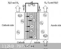
Ozone electrolytic generator
I came up with a picture (attached). It shows chlor-alkali-like setup, where hydrogen is produced at the cat and oxygen and ozone at the ano site.
I suggest the following construction:
A vat, with glued, welded or otherwise jointed groove for membrane
A membrane, 10mm thick, made out of commercial quality clay plate
A cathodic pack, common steel plate, thickness of 1-2mm
An anodic pack, 316 stainless steel, thickness of 1-2mm
Cathodes can be placed intimate with the clay plate, but they can be installed in their own gas traps as well. A 0.5-1% NaOH solution should be boiled
and used as the electrolyte to get higher electrolytic conductivity.
Cell needs a power of 2-6 volts, higher the amperage, higher the yield. A common microvave transformer can be cut apart carefully and the secondary
re-winded for this purpose: using a 30-50mm2 copper cable at 6 turns with primary winding that has equal turns ratio to the mains power voltage input
will generate 6-volt power source of about 1000 watts at 160 amps. The power needs to be rectified from AC to DC, a single diode rectifier is enough,
but it will give only 50% of the nominal power, so if a bridge rectifier is available, or one is willing to make a bridge from 4 diodes, one should
really consider using this method to get 100% of the nominal power to the cell. Rectified DC current is very well suited for electrolysis.
Ozone and O2 should be produced from the anode. All parts must be 316, since ozone will eat through everything but it and teflon within moments. The
cathode can be any junk metal as long as it has high electric conductivity. The conductance of 316 steel is 3% of that of copper(which has about 6A
per mm2), so when calculating the power of the cell, make sure the electrodes have enough cross sectional area or they will bottle-neck the power of
the cell. The gas content of this electrolyte cell should consist as high as 25-30% of ozone off the total amount of oxygenes produced at the anode.
This is because ozone can be used for several reactions, like making AN from ammonia solution, making SO3 from SO2, creating high-quality lead dioxide
electrodes for perchlorate cells, making benzaldehyde from styrene, etc. Ozone will oxidize most elements into their maximum oxidative state within
contact and react detonatively with several organic materials, especially in liquid form.
[Edited on 10-7-2013 by testimento]
|
|
|
bfesser
|
Threads Merged
9-7-2013 at 19:33 |
violet sin
International Hazard
Posts: 1475
Registered: 2-9-2012
Location: Daydreaming of uraninite...
Member Is Offline
Mood: Good
|
|
@ testimento: do you have a source/link for the schematic? does your plan take liberties with materials and are the other normal probs of O3
production not applicable to finished ozone in transit? like temp, does it need cooling. hydrocarbon air contamination, possibly from epoxy in
construction. moisture aided decomp. what is your perceived advantage to this route as opposed the more standard incarnations of O3 production
devices? I mean I can see where the lower voltage higher amperage is easier to buy and use, so nice. but how will the performance match?
not trying to be rude, I love O3 and enjoy reading about it. thanks, an interesting set-up if it works that easy. I look forward to more info
-Violet Sin-
[edit] sorry for a bunch of stupid questions prior, it had been a long work day. after some sleep it was 'much' more apparent
[Edited on 11-7-2013 by violet sin]
|
|
|
| Pages:
1
..
4
5
6
7 |
|


