Melgar
Anti-Spam Agent

Posts: 2004
Registered: 23-2-2010
Location: Connecticut
Member Is Offline
Mood: Estrified
|
|
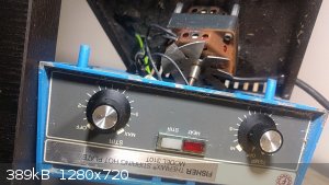
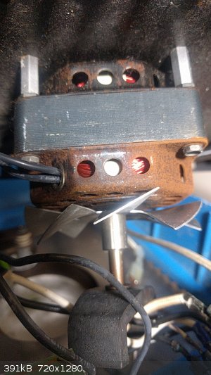
Any ideas for how to control this stirrer motor?
I thought the motor was burnt out when I bought this hotplate, but then accidentally shorted something, and now the motor always spins around top
speed when it's plugged in. There are only two wires going to it, and spinning the rotor doesn't feel like it preferentially stops at any angles. So
AC induction then, with the controller pulsing it or something?
The first step in the process of learning something is admitting that you don't know it already.
I'm givin' the spam shields max power at full warp, but they just dinna have the power! We're gonna have to evacuate to new forum software!
|
|
|
Sulaiman
International Hazard
Posts: 3937
Registered: 8-2-2015
Member Is Offline
|
|
I believe that reducing the current will controll the speed by increasing the slip
https://en.wikipedia.org/wiki/Induction_motor
This can be by reducing the sinewave voltage by Variac or variable series resistance, or by a phase controller
https://en.wikipedia.org/wiki/Phase-fired_controllers
e.g.
http://www.ebay.co.uk/itm/4000W-AC-220V-SCR-Voltage-Regulato...
You can test by connecting a suitable filament lamp in series.
If you photograph both sides of the pcb we may be able to do remote diagnostic/repair
- assuming that you have a soldering iron and a multimeter and are comfortable with ac power,
The type of controller pointed to is probably cheaper than the required spare parts (most likely a s/c TRIAC)
Repair is probably 'better' as no physical changes will be required.
If you look at the pcb where the motor wires connect you will probably find the faulty triac
- two of the triac leads will measure near zero ohms with no power
- if so then it is probably the only fault
(sometimes there is an opto-triac driving the main triac, if so then this is also suspect)
Look up part numbers to find the triac.(or rarely, scr/thyristor and a diode bridge)
P.S. I would expect to find two triacs on-board, one for the motor and one for the heater.
[Edited on 30-7-2017 by Sulaiman]
CAUTION : Hobby Chemist, not Professional or even Amateur
|
|
|
Melgar
Anti-Spam Agent
Posts: 2004
Registered: 23-2-2010
Location: Connecticut
Member Is Offline
Mood: Estrified
|
|
I actually have a couple of SCRs I got off eBay for cheap, that I bought extra of in case I burnt out one. After all, I'd rather pay $4 for two extra
controllers than wait a month to get a replacement because I accidentally broke one. The only problem seems to be that I can't figure out how it's
attached. Eh, I'll try and work on it and see if I can get it off, then post here again once I do.
The first step in the process of learning something is admitting that you don't know it already.
I'm givin' the spam shields max power at full warp, but they just dinna have the power! We're gonna have to evacuate to new forum software!
|
|
|
Melgar
Anti-Spam Agent
Posts: 2004
Registered: 23-2-2010
Location: Connecticut
Member Is Offline
Mood: Estrified
|
|
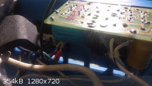
Well, bad news. The controller circuitry contains two ICs. So definitely not a simple SCR. One is a NAND logic circuit, the other a timing circuit. I
could replace it with an Arduino, maybe, but that still leaves me not knowing how the motor is controlled.
The first step in the process of learning something is admitting that you don't know it already.
I'm givin' the spam shields max power at full warp, but they just dinna have the power! We're gonna have to evacuate to new forum software!
|
|
|
zed
International Hazard
Posts: 2313
Registered: 6-9-2008
Location: Great State of Jefferson, City of Portland
Member Is Offline
Mood: Semi-repentant Sith Lord
|
|
Well, I would suspect the rheostat. They sometimes get crudded-up, with metal dust etc., and their resistance becomes erratic..... So that,
regardless of attempted adjustments, they no longer properly control motor speed.
Flush that pesky little monkey out with Freon a few times......Or failing that, WD 40....
Spin it a little when wet, and flush again.
With a little luck, you will be back in control in no time.
|
|
|
Melgar
Anti-Spam Agent
Posts: 2004
Registered: 23-2-2010
Location: Connecticut
Member Is Offline
Mood: Estrified
|
|
The problem is, though, that I shorted something, and now it's running at top speed all the time, regardless of the position of the rheostat, even if
it's off. I actually disconnected the wires just so I could use it as a regular hotplate. I took the controller circuit out though, and can test
things on that.
The first step in the process of learning something is admitting that you don't know it already.
I'm givin' the spam shields max power at full warp, but they just dinna have the power! We're gonna have to evacuate to new forum software!
|
|
|
Twospoons
International Hazard
Posts: 1388
Registered: 26-7-2004
Location: Middle Earth
Member Is Offline
Mood: A trace of hope...
|
|
Based on those two chips I'd bet money its just a phase controlled TRIAC or SCR. Same as the basic phase controlled light dimmers. The timer will be
synching to the mains AC, then turning on the TRIAC at some controlled delay after AC zero-crossing on each mains cycle. The longer the delay, the
less power is delivered.
Helicopter: "helico" -> spiral, "pter" -> with wings
|
|
|
Melgar
Anti-Spam Agent
Posts: 2004
Registered: 23-2-2010
Location: Connecticut
Member Is Offline
Mood: Estrified
|
|
Quote: Originally posted by Twospoons  | | Based on those two chips I'd bet money its just a phase controlled TRIAC or SCR. Same as the basic phase controlled light dimmers. The timer will be
synching to the mains AC, then turning on the TRIAC at some controlled delay after AC zero-crossing on each mains cycle. The longer the delay, the
less power is delivered. |
My testing so far seems to point toward some sort of timed rectification using a TRIAC. The timer seems to be for adjusting the frequency of the
output, which is rectified in the positive or negative direction using the logic chip in some capacity.
I'm toying with the idea of just replacing the whole thing with a videodisk player motor that I have, then building a DC controller for that. I
haven't even figured out what's broken with the board yet, and the rheostat probably still has problems too.
The first step in the process of learning something is admitting that you don't know it already.
I'm givin' the spam shields max power at full warp, but they just dinna have the power! We're gonna have to evacuate to new forum software!
|
|
|
Sulaiman
International Hazard
Posts: 3937
Registered: 8-2-2015
Member Is Offline
|
|
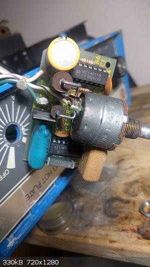
The two ICs are very common and cheap.
Between the blue wire and the blue snubber capacitor is a three-legged device, what is its part number ?
- measure resistance between the inner lead and the two outer leads - one should be open-circuit and one looks ike a diode - I suspect that this is
the triac that has gone short-circuit causing permanent max. power.
CAUTION : Hobby Chemist, not Professional or even Amateur
|
|
|
Melgar
Anti-Spam Agent
Posts: 2004
Registered: 23-2-2010
Location: Connecticut
Member Is Offline
Mood: Estrified
|
|
| Quote: Originally posted by Sulaiman | The two ICs are very common and cheap.
Between the blue wire and the blue snubber capacitor is a three-legged device, what is its part number ?
- measure resistance between the inner lead and the two outer leads - one should be open-circuit and one looks ike a diode - I suspect that this is
the triac that has gone short-circuit causing permanent max. power. |
4004F31. It's a TRIAC. Datasheet.
I thought I had a TRIAC somewhere, but now I'm unable to find it.
edit: Multimeter has a dead battery, I'll get a replacement as soon as the stores open.
[Edited on 8/7/17 by Melgar]
The first step in the process of learning something is admitting that you don't know it already.
I'm givin' the spam shields max power at full warp, but they just dinna have the power! We're gonna have to evacuate to new forum software!
|
|
|
Sulaiman
International Hazard
Posts: 3937
Registered: 8-2-2015
Member Is Offline
|
|
you can check the triac with a battery + (lamp or dc motor or led w/resistor) or a bench power supply with current limitin or ....
but you may as well just order a new triac - it is a common fault in heater controllers.
CAUTION : Hobby Chemist, not Professional or even Amateur
|
|
|


