| Pages:
1
2
3 |
FrankRizzo
Hazard to Others

Posts: 209
Registered: 9-2-2004
Member Is Offline
Mood: No Mood
|
|
MOT supply for electrolysis
After seeing quite a few of those MOT-powered low voltage spot-welder projects, I was thinking that maybe it would be possible to use that beefy
transformer as a low-tech supply for an electrolytic cell. If I were to current-limit the primary with some ballast resistance, and rewind the
secondary such that I get ~7VAC on some 4-AWG wire, could I use a car alternator bridge rectifier to get 4-5V DC at 70-80A without too much loss?
[Edited on 6/2/2009 by FrankRizzo]
|
|
|
hissingnoise
International Hazard
Posts: 3940
Registered: 26-12-2002
Member Is Offline
Mood: Pulverulescent!
|
|
70-80 seems a lot of amps for an ordinary cell---do you need several Kg. in a big hurry, or something?
The most I ever used was ~30A and even then, the electrolyte fairly boiled. . .
In any case I'd be suprised if alternator diodes would handle that current density!
[Edited on 2-6-2009 by hissingnoise]
|
|
|
merrlin
Hazard to Others
Posts: 110
Registered: 3-4-2009
Member Is Offline
Mood: No Mood
|
|
Quote: Originally posted by hissingnoise  | 70-80 seems a lot of amps for an ordinary cell---do you need several Kg. in a big hurry, or something?
The most I ever used was ~30A and even then, the electrolyte fairly boiled. . .
In any case I'd be suprised if alternator diodes would handle that current density!
[Edited on 2-6-2009 by hissingnoise] |
I tend to agree. Unless you have a cell geometry that gives you a low resistance and a reasonably large volume, the joule heating of the electrolyte
is going to be considerable. If you are willing to work with a lower current limit you can get a 50 amp bridge rectifier for $5 at http://www.mpja.com/viewallpict.asp?dept=171. They also have some inexpensive transformers, although the current is less than what you are looking
for.
|
|
|
FrankRizzo
Hazard to Others
Posts: 209
Registered: 9-2-2004
Member Is Offline
Mood: No Mood
|
|
Thanks guys. I'm not going to need that much current but it would be nice to know that I have the overhead if needed. I'm mostly just looking for a
confirmation of theory, that the beefy transformer coupled with some rectification, will give me a cheap low voltage, high current source.
|
|
|
woelen
Super Administrator
Posts: 8150
Registered: 20-8-2005
Location: Netherlands
Member Is Offline
Mood: interested
|
|
Another idea might be to use several parallel rectifiers, each capable of handling e.g. max. 10 A, with its own filter capacitor. Then you can put
multiple cells in parallel. That seems more feasible to me, than having a current of 50+ A in a single superhot cell.
For electrolysis purposes, you do not need a really stiff voltage regulation. AC ripple suppression, however, is something which I certainly want to
have. At 10 A currents you need big filter capacitors (33000 uF or so).
|
|
|
12AX7
Post Harlot
Posts: 4803
Registered: 8-3-2005
Location: oscillating
Member Is Offline
Mood: informative
|
|
I took this route, filtering ripple with another MOT: cut out the windings and add as many turns of 4 AWG as possible. Reassemble with a 1/8" air gap
between the "E" and "I" sections. Connect this filter choke in series with the rectifier output. Above about 20A load, voltage dropped from about 9V
O/C to a steady 6V (maybe down to 5V up at 50A). I used a hunk of steel wire to take up the remaining 2-3V between supply and cell. (Typical
starting current was 20A, up to 50-60A once everything warmed up.)
Unfortunately, the cell had very low efficiency, probably due to the large cathode area. But since I ran it for a couple months, I still collected a
total of about 50 pounds of chlorate and perchlorate.
Tim
|
|
|
jimwig
Hazard to Others
Posts: 215
Registered: 17-5-2003
Location: the sunny south
Member Is Offline
Mood: No Mood
|
|
higher turns density
for higher output amp try parralleling bridge rectifiers.....
and a question -- in transformers one can dual wind - oh say two #12 copper wires to achieve a total of 40amps... this is a question.
secondary, of course......this is certainly easier than one #4......
also probably able to achieve a higher turns density. ?
[Edited on 6-6-2009 by jimwig]
craZy jiM wGGns
--packrat, professional bum. -- once just tired
now REtired.
|
|
|
watson.fawkes
International Hazard
Posts: 2793
Registered: 16-8-2008
Member Is Offline
Mood: No Mood
|
|
| Quote: Originally posted by jimwig | and a question -- in transformers one can dual wind - oh say two #12 copper wires to achieve a total of 40amps... this is a question.
secondary, of course......this is certainly easier than one #4......also probably able to achieve a higher turns density. ? |
Yes, this works, but beware of the gauge you're using and the total resistive heat load you're putting into it. I've tried putting
three windings of #4 AWG onto an MOT, and it just didn't work. #8 AWG, though, is flexible enough. As for current rating, the US electrical code puts,
for a 60°C level, a rating of 40 A on that wire. If 40 A isn't enough, use #6 AWG or double wind with #8 AWG. If this isn't enough
information, you need more than a recipe. It's easy enough to compute resistivity, heat load, etc. and actually engineer the conductor.
|
|
|
dann2
International Hazard
Posts: 1523
Registered: 31-1-2007
Member Is Offline
Mood: No Mood
|
|
Hello,
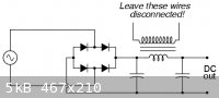
It is difficuly to seperate the 'E' and 'I' parts of an MOT to give an airgap as the core is usually welded. Another MOT simply winded as per what you
have already done and wire connected as in the picture will do the job too (I believe).
There is some info on LC smoothing circuits here.
In my experience the input winding on MOT's have a very skimpy amount of turns compared to a properly designed power transformer (about half of what
is very comfortable). If you wire them up and leave them sitting on the bench without any load connected whey will get very hot. It is better to use
two transformers and wire the primaries in series. This will also in effect give you twice the core area and potentially twice as 'powerful' a set up
(naturally!). This is by no means critical though and the high current drawn by a single primary is not a very big problem.
Use lots of taps on the secondary. If you can use a center tapped output winding (or windings if you are using two transformers) then you need only
two big diodes to give full wave rectification.
If you have a Variac on the input that would be even better. to give smooth output voltage. Since it's a cell you are going to run you would be better
thinking in terms of having a controllable constant current out of this thing.
Anyone suggest how to modify an MOT so that it can be used as an output current controlling inductor?
Would the following work:
Winding on a few turns (similar to what would be done when making a regular high current output modified MOT transformer) of heavy wire onto the MOT
core. Wiring this secondary in series with the load/supply.
With a variable resistor, feeding in a given DC current (into the primary of this MOT) to saturate the core and limit the current at out chosen value.
This total set up will only take 4 MOT's, one large capacitor, two large diodes, heavy wire.
The Mother of all cell supplies????????
I often wondered (as one does) about what shape the current waveform going into a cell has, when the power comes from a raw DC, unsmoothed, Voltage
source. It would be interesting to put a scope (using a resistor ) on a cell to see some time. I think smooth I current is the best to work with if
you are trying to figure out efficiency and times etc.
Dann2
Don't forget some meters!
Whopper of a diode on ebay here
[Edited on 7-6-2009 by dann2]
|
|
|
Taoiseach
Hazard to Others
Posts: 241
Registered: 16-3-2008
Member Is Offline
Mood: No Mood
|
|
I've done electrolysis with a modified MOT from a broken microwave.
I only cut out the secondary winding, being extra careful not to damage the primary. I sawed off the protuding part of the winding, then drilled holes
into the remaining chunk of copper wire and drove it out with hammer blows.
It worked well for electrolysis but IMHO you will never reach the 1000W of power which are theoretically possible. These transformers are not designed
for constant operation and they get considerably hot.
10A is feasible tough and thats more than enough for most electrolysis projects.
|
|
|
watson.fawkes
International Hazard
Posts: 2793
Registered: 16-8-2008
Member Is Offline
Mood: No Mood
|
|
| Quote: Originally posted by Taoiseach | | It worked well for electrolysis but IMHO you will never reach the 1000W of power which are theoretically possible. These transformers are not designed
for constant operation and they get considerably hot. |
Microwave ovens will operate continuously for an hour
or two because the transformers are cooled with forced air. Take away the active cooling system and they overheat. So if you are willing to deal with
active cooling and, as to its potential failures, either (1) put in an overheat detection + shutdown subsystem or (2) deal with the consequences of
meltdown, you can drive these transformers harder.
|
|
|
hissingnoise
International Hazard
Posts: 3940
Registered: 26-12-2002
Member Is Offline
Mood: Pulverulescent!
|
|
A heatsink can be improvised from 3mm aluminium sheet (good contact between trans and sink), add a directed cooling fan and thermal cutout and
continuous use is possible. . .
NSTs, I've found work best, but removing their secondaries takes work.
|
|
|
dann2
International Hazard
Posts: 1523
Registered: 31-1-2007
Member Is Offline
Mood: No Mood
|
|
Hello,
| Quote: Originally posted by 12AX7 | I took this route, filtering ripple with another MOT: cut out the windings and add as many turns of 4 AWG as possible. Reassemble with a 1/8" air gap
between the "E" and "I" sections. Connect this filter choke in series with the rectifier output. Above about 20A load, voltage dropped from about 9V
O/C to a steady 6V (maybe down to 5V up at 50A). I used a hunk of steel wire to take up the remaining 2-3V between supply and cell. (Typical
starting current was 20A, up to 50-60A once everything warmed up.)
Tim |
What exactly is the function of the air gap.
Putting in an air gap will decrease the inductance value (given MOT core size and certain max. number of windings).
The air gap is to stop the core from getting saturated as there is a (large) dc component running through the inductor? Will try in SPICE.
If you leave out the air gap will the MOT core (in the inductor for smoothing) saturate? At what value of DC will it approach saturation.
Someone suggested putting the (MOT cored) inductor before the rectifier (full wave four diode rectifier) so that now there is no DC in the inductor.
Will this work.
I am trying some filter combinations (one Capacitor and one inductor) in PSPICE. But I don't know how to model an inductor with a given core size and
type of core material. It's been a long time since I dabbeled with SPICE.
TIA,
Dann2
|
|
|
12AX7
Post Harlot
Posts: 4803
Registered: 8-3-2005
Location: oscillating
Member Is Offline
Mood: informative
|
|
I tested an MOT primary (intact transformer) and found something like 250At saturation (which was 2A or so through that winding). You can easily get
50A from one MOT, so you'd only get 5 turns worth of filter choke from another, ungapped. Increasing the gap increases saturation magnetization (to
perhaps 500-1k At) while reducing inductance proportionally; since energy goes as current squared, energy storage goes up linearly with gap.
If the core saturates, the "choke" chokes and ripple goes way up.
Putting a choke before the rectifier will soften the AC supply, reducing RMS current, wrecking voltage regulation and doing nothing to output ripple.
Tim
|
|
|
dann2
International Hazard
Posts: 1523
Registered: 31-1-2007
Member Is Offline
Mood: No Mood
|
|
Hello,
I seen a reference to 'putting the inductor in front of the rectifier' here (third post down the page by TVI). Thought I would mention it. Does not make sence to me.
I need to take an angle grinder to an MOT so as to get an air gap into it. Doing some calculations I think you will get 0.08mH from an MOT with a
0.5mm gap and approx. 18 turns (50 amps allowed giving a flux density in core of 2.1 Tesla, ie. close/at saturation). I have little faith in my
calculations!
Book 'Electric Machines' on Google books page 16. 19 , 31 an and 35 if anyone is so inclined.
Does the formula
L = Number of turns * Flux give me a figure for inductance? (page 33 of book)
I cannot get my head around the fact that if you take a core, and separating the E and I pieces (put in an air gap) you will obtain greater inductance
by being 'allowed' to put in more turns of wire than you could place on the core before seperation as when there is no seperation you will get
saturation. (FFS)
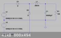
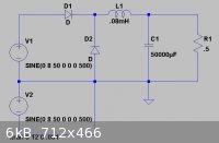
The circuit shown below refused to be analysed by 5spice. Can anyone see anything immediately wrong with it. If you place a bridge rectifier and a
single voltage source (not a tapped transformer) it analysis OK. It is pissing me offf.
Thanks,
Dann2
|
|
|
merrlin
Hazard to Others
Posts: 110
Registered: 3-4-2009
Member Is Offline
Mood: No Mood
|
|
L = (number of turns)*(flux)/current. LTSpice runs your circuit with a 100 ohm resistor as the load.
|
|
|
dann2
International Hazard
Posts: 1523
Registered: 31-1-2007
Member Is Offline
Mood: No Mood
|
|
Thanks for that.
Does the circuit run OK with a 0.5 Ohm load resistor.
I need to get myself a copy of LTSpice. The 5Spice seems to be problematic.
Dann2
|
|
|
merrlin
Hazard to Others
Posts: 110
Registered: 3-4-2009
Member Is Offline
Mood: No Mood
|
|
| Quote: Originally posted by dann2 | Thanks for that.
Does the circuit run OK with a 0.5 Ohm load resistor.
I need to get myself a copy of LTSpice. The 5Spice seems to be problematic.
Dann2 |
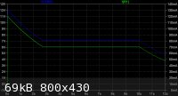
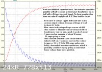
Attached is the .5 ohm version and partial plot showing ripple. The free LTSpice download is at:
http://www.linear.com/designtools/software/#Spice
|
|
|
12AX7
Post Harlot
Posts: 4803
Registered: 8-3-2005
Location: oscillating
Member Is Offline
Mood: informative
|
|
Like I said, gap allows more energy storage.
For example, a ferrite dual E core such as used in your computer might have A_L = 2uH/T^2 and 20At saturation, ungapped. Let's say you can fit 100
turns of 18AWG wire on the core. Then it will have 100^2 * 2 = 20mH inductance, and saturate at 20 / 100 = 0.2A (18AWG is hardly necessary here!),
storing a maximum of about 0.5 * 0.02 * 0.2^2 = 400uJ.
Increasing the gap arbitrarily (how much can be determined based on the core's reluctance) reduces the B field obtained from a given H
(magnetization); since EMF comes from the change in B, the self inductance (L == EMF / dI/dt) drops. The same reduction in B allows more
magnetization before saturation (saturation, in B field, is intrinsic to the material).
Let's say the gap was increased such that saturation = 40At and A_L = 1uH/T^2. Now the same 100T winding has only 100^2 * 1 = 10mH inductance. But
it can handle 40 / 100 = 0.4A, and store 0.5 * 0.01 * 0.4^2 = 800uJ. Indeed, this core would benefit from even more gap, since we still aren't using
that 18AWG wire at its ratings. Let's say we want 2A through it: we need 100 * 2 = 200At for saturation, so the gap has to be increased by that much
more (for this core, I would guess about 1/16" or so). Inductance goes down by the same amount, to 0.2uH/T^2, so inductance is now 2mH. Stored
energy is 0.5 * 0.002 * 2^2 = 4mJ, ten times the ungapped value.
Same thing works for laminated iron cores, of course; Bsat is just a little higher (figure 1T max) for a given permeability. I've measured far more
ferrite and powdered iron cores than laminated iron; I should measure a bunch some day.
Notice that, if you can't reach a high enough current density to saturate the core, adding a gap only reduces the inductance; you don't need a higher
saturation value if you aren't reaching it in the first place. This might've been your source of confusion.
Tim
|
|
|
dann2
International Hazard
Posts: 1523
Registered: 31-1-2007
Member Is Offline
Mood: No Mood
|
|
Thanks for that.
There is a discussion regarding gaps (no diagrams unfortunately)
here . It's a bit out of my depth but though you might be interested.
At what air gap size does diminishing returns set in?
Surely you cannot simply go on increasing air gap size and getting good returns (in this type of application)?
@Merrlin
I changed a setting in 5Spice from Fine to Course (dynamic step size) and it is now analysing OK. HNGAFC what dynamic step size is all about!!!!!!!!!
I sawed an MOT in half and can get 0.35mH per turn with an air gap (piece of plastic) of 0.4mm.
Now all I need is the ballast on the input as Sir Frank Rizzo suggested at the start.
Dann2
|
|
|
merrlin
Hazard to Others
Posts: 110
Registered: 3-4-2009
Member Is Offline
Mood: No Mood
|
|
In numerical solutions there is usually a tradeoff between speed and accuracy. In solving, the timestep may be variable. In LTSpice a maximum timestep
can be specified and at times I have found that a very small maximum timestep can be impractical due to the solution time required. Dynamic step size
appears to be similar to maximum time step.
|
|
|
12AX7
Post Harlot
Posts: 4803
Registered: 8-3-2005
Location: oscillating
Member Is Offline
Mood: informative
|
|
How did you determine this? Your units aren't correct: it's inductance per squared turn. That could be a big error.
Tim
|
|
|
dann2
International Hazard
Posts: 1523
Registered: 31-1-2007
Member Is Offline
Mood: No Mood
|
|
Got that totally wrong.
I would 25 turns on an MOT core and got 8mH (measured with a miltimeter, no DC present in the coil). Then I wrongly assumed I was getting 8/25 = 0.32
mH per turn. (I actually wrongly reported 0.35mH per turn (doubly wrong)).
Dann2
|
|
|
12AX7
Post Harlot
Posts: 4803
Registered: 8-3-2005
Location: oscillating
Member Is Offline
Mood: informative
|
|
Ah, then that's going to be 8000 / 25^2 = 12.8 uH/T^2. But that's also initial permeability. Higher up the B-H curve, permeability rises (maybe
about double), then falls as saturation is approached.
Tim
|
|
|
dann2
International Hazard
Posts: 1523
Registered: 31-1-2007
Member Is Offline
Mood: No Mood
|
|
Hello,
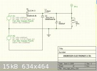
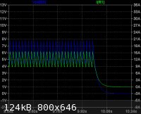
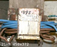
Got around to putting a 'Killawatt' meter on the input of a rewound MOT. The thing dissipates 160 Watts of power with no load connected to the output.
The core gets too hot to touch. It draws 2.4 Amps at 234 Volts with a Cos Theta of 75 Degrees. When you put the Voltage down to 210 Volts the primary
now only draws 1.0 Amps. I guess core is getting close to saturation as the number of windings on the primary is very skimpy.
This would be a problem with PVC covered wire as the PVC may soften enough to become cut by the sharp edges of the core. Keep it in mind. Better to
use two transformers with the primaries in series if you have them, or a Variac on the input would be great.
The one in the picture can suppy 50 Amps (into a Graphite rod resistor, after a rectifier and 68000 Micro Farad capacitor) continous. I put 173 Volts
into MOT using a Variac.
Doing some more testing.
Regarding the inductor I was messing around with (gaped MOT). When I wound on some turns onto the sawn-in-half MOT with a 0.4mm air gap, I can only
get approx. 0.08mH which is a dissapointingly small inductance. It helps no doubt but I would like about 2mH minimum.
I have a large transformer from elsewhere. I might try that.
Setting up a 'raw DC' power supply to see just what sort of Current waveform goes into a Chlorate cell when powered with it.
See
http://www.qsl.net/i0jx/supply.html
for a description of the Resonant Choke Power Supply. You only need one tenth (approx.) the inductance for to get similar smoothing. Would this work
for us in a Chlorate supply?
Cheers,
More later.
Dann2
|
|
|
| Pages:
1
2
3 |


