| Pages:
1
..
3
4
5
6 |
not_important
International Hazard

Posts: 3873
Registered: 21-7-2006
Member Is Offline
Mood: No Mood
|
|
While it won't be the same wavelength, why would that bee a problem? The spatial location is what is important. The problem is that the
fluorescent layer is not directly on the sensor, unless you coat the sensor surface it's done), but above it - meaning that a small spot will be
visible to several adjacent sensors giving less resolution.
BTW - there are N-photo phosphors that absorb several photons and emit one or one in the 'visable' and some fairly deep in the IR. Then can fluoresce
at wavelengths shorter than the exciting one, or at the same or nearly the same) wavelength, although there's little use for that as the intensity
will be lower than the exciting intensity.
The lamp - standard RF plasma, an electrodeless arc. No electrodes means no electrode evaporation, in some cases lower power consumption as there's no
electrodes for heat to follow out of the bulb.
|
|
|
aliced25
Hazard to Others
Posts: 262
Registered: 31-7-2010
Member Is Offline
Mood: No Mood
|
|
I'm actually interested in trying to make one of these to get my eye in so to speak. I'm looking at the 640-660nm range of Laser Diode (with internal
diode for feedback), with an external cavity. I would prefer to use an aspheric lens (as in the attached paper by Dunn). I honestly don't think the
cooling should be a huge issue, the duty cycle is pretty low.
Now, with the PWM controllers on the various DSP's, is there any reason they cannot be utilized to control the laser? I mean, it is not like I am
using it as a transmitter and need a multi-GBPS transmitter driver is it?
I'm thinking that if I line-lock the Diode with feedback, it may be possible to add in a <100l/mm laser line narrowing beamsplitter (it could even
be ruled) as a component of the partial reflector, the wavelength that is in the center would be the one used, the others would be reflected back into
the diode and used to line lock the diode (needs a bigger diode as it can only be run at part power or it will overload with the feedback - Here is the thesis from Dunn that I am referring to).
Anyone got any ideas on how many mW of power I'd need in order to get a decently bright (ie. measurable) response in the Stokes-shifted radiation? It
will impinge upon the NIR end of the spectra ~850nm is the upper edge IIRC.
The sensor, a simple 2MP CMOS camera is way cheaper than the filters, the fiber, the lenses, etc. could be utilized then to convert the spectra into a
digital signal which can then be processed (the signal processor can run algorithms to remove spectres/ghosts, dead pixels, hot pixels, etc. by
averaging the entire column).
It looks a sight easier than the NMR as a first effort is all.
[Edited on 5-11-2010 by aliced25]
|
|
|
not_important
International Hazard
Posts: 3873
Registered: 21-7-2006
Member Is Offline
Mood: No Mood
|
|
Raman light is 5 to 7 orders weaker than the exciting light, shouldn't be too difficult to put that against sensor data along with focusing optics to
determine needed laser power.
Remember that colour camera sensors are less sensitive than grey scale ones, roughly 2/3 of the light of a given wavelength is wasted on the other two
colour channels. They generally are noisier than CCDs intended for such work. And you've very little control over the operation of CCD and
accompanying data collection; low end cameras are optimised to deliver acceptable picture capture using common light levels used by humans, generally
much brighter than the light a Raman system will be presented with.
You are thinking of all the hardware as idealised, ignoring the problems of scatter and of higher order spectra from gratings; those will limit the
sensitivity of your device and not unlikely create ghost peaks. You'll not get away with lenses, attempting to drag the Raman emissions out of the
scattered but not shifted laser light is going to take a filter or really well constructed dispersive systems. Even cleaning up the laser light
before sending it to the sample will take at least a well built double monochromator.
There are reasons that commercial and research instruments are expensive and complicated, it's not just for the hell of it. Demonstrating an effect
often is not too difficult, having be an useful analytical tool is generally more difficult.
BTW | Quote: | | . I honestly don't think the cooling should be a huge issue, the duty cycle is pretty low. |
The duty cycle of the laser? Matching that to the timing of the camera should be fun, CW is more typically used unless you directly control the CCD.
|
|
|
aliced25
Hazard to Others
Posts: 262
Registered: 31-7-2010
Member Is Offline
Mood: No Mood
|
|
The cycle is going to be pretty short, the camera and the laser are both controlled directly. Matching the two is a matter of turning both on. The
duty cycle in this case will be the time it takes for the CMOS Image Sensor to collect a thousand frames, which is fuck all. 1,000 frames, each of
which is effectively a statistically improved average of 1,000 single pixel high captures, will effectively give an average of 1M single pixel high
captures. This will allow for the Constant Wave Laser output to be shortened dramatically, thus reducing heat and effectively removing it from the
equation.
The Camera I am looking at is a 2 MP CMOS camera, the light captured by it and by CCD's designed to be monotone is really down to how the RAW format
data is played around with. In terms of accuracy, the single line sensors cannot effectively remove the value of a hot/dead pixel without skewing the
data in that space appreciably, it is illogical to suspect that they could. With a thousand pixels in height, there is the potential to remove a
single/multiple dead/hot pixels by averaging or getting the mean and excluding any value outside a percentage of the median, etc then getting the mean
of the values for that column.
I don't see your concern insofar as conversion of the RAW data into RGB then greyscale. Yes it does frig about a bit more than I'd like, but it is
digitized from the camera, so the data shouldn't really be too much problem with the conversion. I've actually manually converted the RGB spectra I've
gotten with a camera into greyscale, it works fairly well. I am of course in the hunt for a monotone camera module in the 2MP range, because I
honestly believe that the capability to remove dead/hot pixels with less overall effect on the averaged values is a better way of collecting the
spectra. Add to the that the fact that each and every value on the single pixel high result that comes from the averaging of the spectra down the
height of every column is effectively an average of 1,000 (or more) image captures with the single pixel high units and the benefit in terms of
accuracy should be obvious.
Put it this way, each column of pixels is at a calculated angle from the grating. Each column is 1,000+ pixels high. Each column will receive a
spectral value (intensity) from the diffraction of the light through the grating at every pixel. The median of each column of pixels is calculated and everything outside say 1/4 of the value thereof is replaced with the median value (which gets
rid of the hot/dead pixels). The mean is then taken of the pixel values, including the standardised deviation pixels, to give a representative value
of the value over the entire column. This is kept as the mean value in terms of intensity of that pixel position. Each column is then treated the same
way, to give a mean intensity per pixel position. The trigonometric conversion of the pixel position into Wavenumbers (cm<sup>-1</sup> and
Wavelengths (nm) will also take into account the known transmission curve values of the filter(s), equalizing the transmission. This gives us the data
pairs for the mapping of the values, intensity v Wavenumber/Wavelength.
That will give a better result than the alternative single pixel high sensors, which try and approximate and/or ignore dead/hot pixels. It will also
give a result which is effectively an average of some 1,000+ image captures with the single pixel high sensors, which are statistically
improved/modified to give a better representative value. Statistical anomalies, such as higher order wavelengths & spectral ghosts, will be
removed by the use of the median dispersion technique. All of these tools are built into a variety of C/C++/C# image processing libraries.
But bottom line, I personally dislike the single-pixel high sensor concept. It does not allow for the fact that if there is an actual problem pixel in
the array, it cannot be effectively/accurately accounted for or removed from the image without building in an approximation/guess as to its spectral
data. That cannot help but skew the data coming therefrom, there can be no meaningful connection between the approximation of that data and the
reality of the spectra at that point.
PS Also, please check out the paper by Hong (attached) with a "claimed" linewidth of 0.06nm with a single Littrow-type setup with an external cavity.
I am trying to think up a way to utilize the low-groove, high-dispersion gratings that are designed to effectively separate the laser-line to give
narrow beamwidths (<0.5nm) by basic refraction through a transmission grating(<100l/mm). That idea with the concept suggested in Dunn's paper (cited above) should allow for the narrowing of the laser line as well as the
locking of the laser (provided it has a feedback diode), while minimizing parts count and allowing for a smaller module to get the laser line from the
diode into the fiber, with the narrowest possible laser-linewidth. The splitting of the beam, so that we could take the 0<sup>th</sup>
order beam (straight-through), while allowing the others to be reflected back into the diode, should allow for a straight-line module from the diode
to the fiber of minimal linewidth (of course, in terms of effectiveness it is quite probable that we would have to take a different order, in which
case we would have to tilt the transmission grating, which would improve the effectiveness anyway, as the order taken would also have a reflected
counterpart, the use of which as feedback would lock the diode onto the appropriate mode.
PPS As to the Raman Lightwave beings 7-8 orders lower than the exciting light, that is why I am looking at the DVD burner range of diodes as the
incident light source (640-660nm, ~100-150mW). They are designed from the outset to be high-powered, feedback locked sources (that is why they
incorporate the feedback diode). They are also mass produced, mature technology (read fairly accurate and cheap), as are the lenses and optics that go
along with them.
Attachment: Hong.Design.and.Characterization.of.a.Littrow.Configuration.External.Cavity.Diode.Laser.pdf (234kB)
This file has been downloaded 4493 times
[Edited on 6-11-2010 by aliced25]
|
|
|
not_important
International Hazard
Posts: 3873
Registered: 21-7-2006
Member Is Offline
Mood: No Mood
|
|
RAW in a colour camera is in effect RGB; it's not the data format but rather how the sensor is built - 3 cells per pixel, one per colour band meaning
2/3 (actually between 2/3 and 3/4) of the light of a given wavelength is wasted. A "B/W"monochromatic sensor has no such losses, and can be had in
2D form. It also has a simpler response curve, rather than the 3 curves of a colour sensor in which there is overlap between channels you can filter
the unwanted ones out in software, true, but its extra work)
When an image sensor is built into a camera you lose full control of its operation, the control is busy being a camera. At low light level (ie Raman)
you need to operate it differently that when taking photographs under lighting typically supported by at least lower end cameras.
Remember the need to run a transform on the data to compensate for the sensor column alignment vs spectral lines before doing any further signal
processing.
Regrading duty cycle - I am doubtful you can push a low end camera faster than 10 frames a second, well over a minute for your thousand samples. In
the real world, and given the small mass of the laser system, that's 100% duty cycle. If you can pop it on and off for each frame, another story.
However powering up and down usually cause non-stable and off frequency operation for a period of time, in some cases for seconds or longer.
Calibrating the sensor may be more work that you expect, right now I'm assuming you've not done it before.
This all is pretty old hat to me, the concepts behind the bad cell removal and all that go back decades and are used in may other fields as well.
I've worked with specialised hardware that did cross correlation between 5 scan lines data in real time to generate a 5 line time delayed noise
filtered feed, and that was decades ago.
|
|
|
aliced25
Hazard to Others
Posts: 262
Registered: 31-7-2010
Member Is Offline
Mood: No Mood
|
|
The camera is rated for 360 fps, so <3 seconds for the 1,000 samples (it is actually a high-ish resolution web camera), so that brings the cycle
down to around 3 seconds and a laser diode shouldn't have too much opportunity to generate sufficient heat in that period.
I know what you are saying with the RGB/RAW/YUV image formats, but unless I can find a decent Monochromatic CMOS Module in the 2MP range, it is really
Hobson's choice. I am still looking around for a decent supply of a monochromatic sensor (CCD/CMOS) in this size, they do exist, but it is either too
difficult to source or the lack of documentation is sufficient to make me very wary of purchasing the same (I have tried to utilize other sensors that
lacked documentation and it is just too hard to work out how to build it and utilize the components thereof). That said, I am still looking, if anyone
knows of such a camera (there are several makes, Toshiba, Samsung, etc.), let me know (by PM if necessary).
When the image sensor and the image sensor controller are built into a normal camera you do lose control over the majority of the functions, but when
you control the image sensor and the controller you should be able to alter the way the data is dealt with (which after all is the limitation on using
standard cameras).
With the sensor calibration, I'm building a neon, xenon or krypton light source into the board that can be used directly for calibration. The high
power torch bulbs are what I am looking at for that, minimal power, maximum result.
Given your experience I look forward to working on the project then, it is always nice to have someone to ask the questions that need answers. The
alternative is to reinvent the wheel every time a problem is hit.
Once I have the rest of the pieces in place, I'll try it out with a DVD grating, or three gratings from around the outer edge of a DVD and a web
camera. Not so much as an analytical instrument in its own right, but more to prove the concept. I'm actually acquiring bits and pieces at the moment
so it is on its way. As the concept is proved, I'll gradually change one part (or more) at a time, in the proof of concept setup until we have a
prototype.
Each step will be documented on here, that will allow people to pick it to bits (faster, less formal version of peer review in my book, hopefully it
works better too). It is suprising how cheap the components are if you are willing to look around a bit. For starters the webcam based model will
allow for us to actually get spectra to work on. When the basics are worked out, it'll be time for another step.
And you are right, I haven't calibrated the sensor before, but I'm more than happy to in the furtherance of an interesting part of my hobby. That
said, there are an awful lot of fairly low-end articles where they have managed this with some very simple optics and even simpler light sources. Once I can replicate their
results, I'll push on to more advanced optics and light sources (and algorithms and digital filters).
I personally believe that there has been insufficient attention paid by amateur's to instrumentation. Yeah, it costs money, but it costs less to
design and build these than it does to refurbish a $10K spectrometer, and the understanding of how the instrument works has to be higher.
[Edited on 6-11-2010 by aliced25]
|
|
|
not_important
International Hazard
Posts: 3873
Registered: 21-7-2006
Member Is Offline
Mood: No Mood
|
|
The noble gas lamp is good for wavelength calibration, and should be included a s part of a sample scan. But sensitivity calibration requires a known
intensity and spectral curve such as a standardised tungsten lamp; the optics for that are simple. I need not be done very often, although some
instruments calibrate each day against a tertiary standard bulb built into them.
I suspect that frame grabbing at that speed isn't going to yield high sensitivity; try running the camera where the only illumination is a wide band
emission LED being feed with about a microwatt or two of power.
Three seconds power on should be sufficient for the LED to walk all over; you'll need to quantify it first to make sure it gives you useful output.
That simple Raman spectrometer integrates for many seconds, 10 to 60 are mentioned in the paper; far longer than the 3 seconds you're speaking of.
Also note that it is simple in part because of the box labeled 'spectrometer', much complexity is hidden in that including the fact that it is not
very sensitive to the lasers wavelengths.
|
|
|
aliced25
Hazard to Others
Posts: 262
Registered: 31-7-2010
Member Is Offline
Mood: No Mood
|
|
Well I had another look around, there is a much better camera, around 30fps, @1.6MP & it is monochrome (about 5 times the price). It certainly
does look like a better unit, although I'll have to go for cooling for the diode & the UV-NIR light (ah well), ~$25 for the sensor.
As to the UV - the xenon lamps go right through the UV-NIR (actually past the CCD/CMOS sensor's ability to collect it 185-~2000nm). Anyone got
anything on the xenon lamps, I know the HID ones are filtered to remove UV, but what about the xenon bulbs for flashlights/downlights? Anybody in a
position to find out whether any of them are UV friendly? The alternative is one of the major manufacturers and I'd expect them to run @ around
$250-300/ea.
The laser diodes are not too bad, expect the 100mW end @ 635-650nm to be around $20 and I was right (the ones with the feedback diode).
Anyone got any idea of the lens setups needed to get the laser/UV-NIR light into the respective fiber, then into the sample(s)? Then collect it from
the samples and into a multi-channel spectrometer?
|
|
|
aliced25
Hazard to Others
Posts: 262
Registered: 31-7-2010
Member Is Offline
Mood: No Mood
|
|
OK, I'm going to build a simple testbed. I've got a 30mW Rated DPSS 532nm Module (Battery Powered), an Orange Plastic Filter (approx. same color as
OG-550), that the Green won't go through, several plastic cuvettes and some mirrors, etc. I've also got a Microsoft LifeCam VX-1000 (with the
infra-red filter removed from under the optics) and a blue plastic filter (from Edmund Optics), which will allow the green through, but will stop and
stray light.
Presuming I shine the light in from the left side of the cuvette, and take the light from the front (ie. 90' to incident) through the orange plastic
filter, then use a 45' mirror to direct that light onto a reflective holographic grating (I'm using one from a CD - so ~ 600 l/mm), and put a solid
wall with a slit 45' to the mirror (extend the right-side of the cuvette holder), then the grating should be at what angle to the wall in order to
collect the orange+ wavelengths?
I'm going to have to sit down and work this fuck out
|
|
|
not_important
International Hazard
Posts: 3873
Registered: 21-7-2006
Member Is Offline
Mood: No Mood
|
|
Note that some XE HID, such as automotive headlamps, are more properly metal-halide lamps, with quite strong emission lines.
Flashlight bulbs with the 'xenon' tag are xenon-filled incandescent lamps, argon was used in the previous generation. The inert gas reduces the
evaporation of tungsten from the hot filament, giving a long life for hotter (brighter) lamps. But they're still tungsten incandescents, with the near
blackbody spectrum for their temperature which means a big hump in the yellowish region.
Pure Xe lamps have noticeable spikes in the VNIR, and fall off below 400 nm, but are fairly close to a flat spectrum between those regions, and from
above 1000 out a bit past 2000 nm. They are expensive, as are their power supplies. Because of the spikes and fall-off a differential mode, with
reference and sample beams and either 2 detectors or a rotating mirror style beam diverter, is often used. Comparing the reference beam and that
passed through the sample allows nulling out of the deviations from a flat source. Note that there can be some shifting over fair short time scales,
unless you know how your particular lamp acts you can't trust storing a reference for computational subtraction, you need to actually compare on a
short term basis.
http://jp.hamamatsu.com/products/light-source/pd024/index_en...

As for getting light into the fiber, you want input couplers. This can be simple lenses or a form of telescope. Lots of literature on them. Ditto for
the output, although in some cases you don't need any lenses. Beams from the fiber should be small enough that you can simple locate both fibers in
the same region. BTW - the fiber for the laser should be low in Raman generation, or you filter it through a narrow pass filter between the fiber and
sample.
|
|
|
aliced25
Hazard to Others
Posts: 262
Registered: 31-7-2010
Member Is Offline
Mood: No Mood
|
|
Yeah, the Short-Arc Xenon Lamps are pretty fucking spectacular actually - they kick shit out of Deuterium Lamps, less cost more light - Trouble is
standard quartz fiber ain't gonna get you far (fluorescence @ 250??), which is why no-one has one for sale that gets much below 300nm. The price list
at MS Scientific is a good read.
I'll have a fairly short distance between the laser & the sample when I do it properly.
At the moment I'm just frigging about proving it can be done
Codeine Phosphate + Paracetamol in the sample should have some effect.
PS I'm checking out some of the HID Lamps, I'm sure some of them get off cheap by including a glass sleeve (to absorb UV - the alternative is a
special - read expensive - grade of quartz, for once the cheaper the better might be the option). Then again, I don't expect anything much lower than
300nm out of them.
PPS I'm Looking at GRIN Lenses (for the Laser) with a silica spacer (with as little air as possible), I'm thinking about using a glass prism to catch
the narrowed line from a grating, then an aspheric lens straight into the GRIN Lens. I'm looking into the UV fiber as well, but if you want to go
under 300nm, the only real answer is probably going to be the aluminium hollow core fiber, that or photonic crystal and you don't need much of that to
raise the price through the fucking roof. Silver Hollow Core would probably work (vacuum inside), but I remember reading an online paper that it had
appreciably higher losses than aluminium (then again, silver mirrors are a fucking lot easier to make than aluminium ones). I'm thinking that with a
silver hollow core, you could probably get away with a hollow plastic tube & form a mirror on it. Alternatively, a plastic tube with a conductive
plastic & plate it, although with a vacuum how would nickel work (I'm thinking it is unlikely to corrode)?
|
|
|
not_important
International Hazard
Posts: 3873
Registered: 21-7-2006
Member Is Offline
Mood: No Mood
|
|
The special grade of quartz is to pass the short UV, not to filter it. Thus the HIDs you're talking about are going the opposite of what you need and
certainly will be weak in the vacuum UV region; the ozone-free curve in blue is similar to the HIDs you're talking about. Also make sure they are
pure Xe, with no Hg in them, else the mercury lines swamp everything else.
|
|
|
aliced25
Hazard to Others
Posts: 262
Registered: 31-7-2010
Member Is Offline
Mood: No Mood
|
|
Go read up on HID Lamps - they have a special grade of quartz specifically to STOP UV. The Short-Arc Xenon Lamps have a different grade of Quartz (Ozone Free) to pass it, but there is a different additive in the UV Absorbing
Quartz that stops everything under ~400nm so as to qualify for use as headlights. As the Low-Cost HID Lamps have a second sleeve that is essentially
normal optical glass (that is cheaper than UV-Stop Quartz and every bit as effective at absorbing <400nm), that is why I am suggesting that the
cheap HID Tubes might be worth a look, especially if anyone has the capacity to check the output. They don't use UV-Stop Quartz so they won't be using
Ozone-Free Quartz either, so no, they won't output very well at all <300nm, but if they can go down to the 300nm mark, then they will perform every
bit as well (given they go all the way to about 1600nm IIRC, although nowhere near as flat as the short-arc xenon) as the Deuterium/Tungsten Halide
Lamps used in the Ocean Optics Fiber-Based UV Spectrometer (which is only rated to 300nm & given that neither Tungsten Halide or Deuterium are
exactly flat either), for a lot less fucking money (and a hell of a lot cheaper to replace).
As the majority of Quartz fibers (certainly all that I've found to date) absorb UV @~250-280nm (thus the need for photonic crystal / hollow core
fiber), the makers of the various Fiber-Optic Spectrometers don't have anything I've seen that goes under 300nm (Kind of a waste of a Deuterium Lamp
I'd have thought, but there you go). I'm wondering if anyone makes an Ozone-free Quartz fiber, if so that should be capable of carrying the UV from
185-2000nm (as it is transparent thereto), but I haven't seen any mention of it (which is kind of a shame - hardly seems worth buying a lamp that can
go that far if the light won't be utilized).
I'm actually beginning to wonder if polished aluminium waveguides (with an internal vacuum, or can I fill it with argon/whatever?) might not be the
way to go. Yes, I'd need mirrors and if it is going to be portable, they'll need to be set it in place absolutely (or be adjustable from outside).
I'll also need lenses, but I'm sure I can find Ozone-Free Quartz lenses & Optics if I look about. A beamsplitter will also be required. It is just
not really feasible to utilize fiber when it is not up to the task.
But the only reason I was thinking about the HID's is that if they do output in the 300nm-1600nm range (albeit up & down all over the place, like
D2/Tungsten Halide really), the ones without the special UV-Stop Quartz sleeve (or the ones in which it can be removed), would truly be a decent
replacement for the $1500 light-source in the majority of Fiber UV Spectrometers that do the same numbers. I'm serious about that, I personally am
looking for something that will carry the 185-2000nm light generated by the Ozone-Free Xenon Short-Arc Lamps (I'm trying to get quotes, looks like
there could be some decent buys ~$150/lamp). That saves fucking around with D2 Lamps (~$300ea) and then tungsten Halide as well, in order to get a
smaller envelope.
PS One really has to be sure that everything is Hg free nowadays, otherwise I could not recoup my costs all that well, given that pretty much anything
that contains Hg/Pb is verboten in Europe (especially with basic electronics, I suspect more will follow).
PPS I tried out the mini-Raman, but the **I^(*&*)(*)(*)(* Camera is playing up now (If it isn't one thing it is a fucking 'nother). If one more
shitty little Laser Module lets go on the blue wire, I'm going to have to go and buy some bits and bobs to build a module out of the 200mW 650nm
Burner-Diode Laser's I've got on my desk. I have a proper Filter specifically for that wavelength if that happens (but it will slow shit down).
[Edited on 15-11-2010 by aliced25]
|
|
|
not_important
International Hazard
Posts: 3873
Registered: 21-7-2006
Member Is Offline
Mood: No Mood
|
|
From
http://www.tfhrc.gov/safety/hsis/pubs/04146/introduction.htm

Or just look at one through a prism or off a CD/DVD, the lines are obvious.
|
|
|
aliced25
Hazard to Others
Posts: 262
Registered: 31-7-2010
Member Is Offline
Mood: No Mood
|
|
The alternative to taking the 0th Order and using the +/- 1st order for feedback control is to split the beam at the grating and utilize the +/- 1st
Order beams as Equal outputs (which they are), line-narrowed laser light sources. If the 0th Order is coupled to a photodiode, which is then sent to a
comparator which controls the power supplied to the diode, it will generate a positive/negative error signal. Altering the power-supply to minimize
the error signal, will effectively modulate both frequency & temperature induced effects on the outgoing signal, allowing for the production of a
very small, very accurate, temperature & frequency modulated, narrow line- dual-output laser.
Yes, but the majority of those lines are from the Tungsten-Halide component. As the alternative option is a Deuterium Coupled Tungsten Halide Lamp, I
can't see that it would be much improved.
 (From the Manufacturer, Ocean Optics, website, so take it with a grain of salt). (From the Manufacturer, Ocean Optics, website, so take it with a grain of salt).
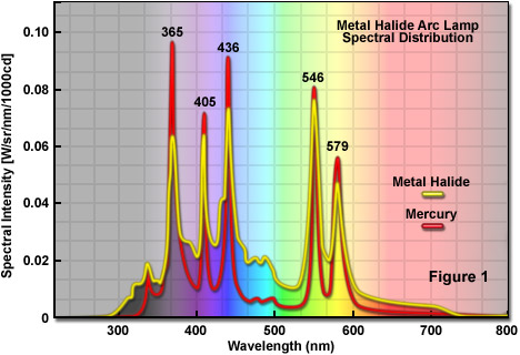 (From Zeiss Website, rather more believable & has many of the same/similar peaks as the HID). (From Zeiss Website, rather more believable & has many of the same/similar peaks as the HID).
I have to work out how I come up with the diffraction angle through a transmission grating (anyone got a formula? I'm busy trying to design the
electronics), but if the two (+/-) 1st order signals are equal (and they are supposed to be), then I don't see the utility of trying to split the
light later or even of trying to direct the light back to the diode (which while it apparently works is less effective than external photodiode based
modulation). The papers are out there if you look, but if we use the 0th order, which should stay the same if that is the one we modulate from (and so
will the others), then we avoid repetitive & unnecessary dithering/oscillation with the light output, while we output two signals which are
collimated and can be output to fiber optics.
[Edited on 15-11-2010 by aliced25]
|
|
|
aliced25
Hazard to Others
Posts: 262
Registered: 31-7-2010
Member Is Offline
Mood: No Mood
|
|
As it stands at present, I'm going to press on with the design of the Fiber-Raman Spectrometer, with a multi-channel Spectrometer Design and two
Sample Holders (one for the Analyte + Solvent the other for the neat solvent). The third channel will be for the production and direction of the light
from a neon/krypton torch bulb (2-3V) so the known spectra can be collected on the third channel. As the Spectrometer will be built from quality parts and
will (for the moment) utilize only Image J (or similar) to determine the spectra (Until I can get around to programming OEM Software, or sourcing
someone else to do so). The filters will be quality units, as will the holographic gratings in the spectrometer, the Optical Fiber, the connectors and
the laser module. As I will have to recoup costs, please be aware that someone else will be offering these for sale, either complete or as a kit.
When I work out how to direct the UV Light properly within a portable, cigarette-packet sized unit, I'll add it. With UV-NIR and Raman, it should be
quite a useful diagnostic/analytical tool. Be aware that due to the insane prices on the UV-NIR Light sources, that version will not be as cheap as
I'd like, whether to design, to build or to onsell. I will sort this shit out then I'll start on the NMR again.
|
|
|
not_important
International Hazard
Posts: 3873
Registered: 21-7-2006
Member Is Offline
Mood: No Mood
|
|
A torch bulb is an incandescent lamp, meaning typical black body curve, no lines. They can be useful for determining the sensitivity of sensor at
given wavelengths - provided the bulb has been related to a standard lamp - by comparing the detector output to the calculated flux at each
wavelength.
|
|
|
aliced25
Hazard to Others
Posts: 262
Registered: 31-7-2010
Member Is Offline
Mood: No Mood
|
|
What I'm seriously considering is utilizing the fact that if we shine a Laser diode at a transmission grating (see the whitepaper attached) we can
maximize the transmission of equivalent +1<sup>st</sup> & -1<sup>st</sup> Order wavelengths, while minimizing the loss as
0<sup>th</sup> order transmission (which we can pick up with a photodiode at the end of the cavity (avoiding having to fuck around with
Littrow/Littman-Metcalf Configurations).
Getting the feedback from a photodiode mounted directly in-line with the diode, allows for feedback to the Comparator, Current Ouptut DAC Laser Driver
& Controller, generating a modified +/- error signal. By minimizing the error signal, the 0<sup>th</sup> Order remains the same
regardless of frequency/temperature changes (NB So too, the +1<sup>st</sup> & -1<sup>st</sup> Orders remain the same).
The concept of utilizing external digital modulation is not new (http://pdfserv.maxim-ic.com/en/an/AN1811.pdf), the idea of utilizing the equal magnitude split laser linewidth appears to be.
I see little point in splitting the line later on when it can be accomplished in such an effective manner using the same parts as are needed to narrow
the line to <100kHz. Dual-Narrow Linewidth Laser Line Source sounds good doesn't it? Especially given the cost of 650nm Laser Diodes ($10-40
depending on where you source them from). That would enable me to build a connector for the + & - line on the front of the Laser generator and
expect to get ~40mW on each (from a 100mW (standard)/150mW(pulse) diode). That should be ample for my application I'd have thought (anything higher
than that stands a real risk of burning the sample & the sample container).
With the sensor, I've found a 5MP Aptina LLC Monochrome Camera Module (MT9P031I12STM - getting the app.notes etc. out of Aptina is a bit of a fight).
The Grating I'm sourcing now, actually I have sourced several I just have to pay for them. But the use of the external photodiode and digital
modulation to compensate for both frequency & temperature, seems like a saner choice than trying to keep the diode cool, etc.
Being able to take-off both laser-lines from the unit in simple patch-cords (Single-mode) and take them to the samples (Analytic = Analyte + Solvent
& Reference = Solvent) will allow for the rapid collection of Raman Spectra from both, comparison of the two will give the Raman Spectra of the
Analyte itself. Comparison of both with the Neon/Krypton Spectra will allow for alignment.
The electronics are still being designed, the laser is just about finished being designed. The Camera is waiting on App. Notes from Aptina LLC, but it
should be able to be interfaced with the Mixed Signal Microcontroller. The Dual Current Output Dacs & the Comparator on the same MSP, will allow
for the efficient external digital modulation of the Laser Diode, while the USB 2.0 Connection (and the requisite multi-stage LDO, which can charge a
Li-Ion Battery and run the Laser, the Camera, etc.), in addition to the 12V DC Jack (also run to the same LDO) will ensure that the entire unit has
sufficient power.
The problem is now the design of the 3-channel Spectrometer, how to split the one grating into 3 compartments without stray light? Also, do I need
optics on the Aptina CMOS Module? I've seen some articles where the bare CMOS Chip is used, but I'm not sure.
Attachment: Laurila.etal.Tuneable.External.Cavity.Diode.Laser.at.650nm.Based.on.a.Transmission.Diffraction.Grating.pdf (152kB)
This file has been downloaded 866 times
Attachment: Ibsen.Photonics.White.Paper.Fused.Silica.Transmission.Gratings.pdf (499kB)
This file has been downloaded 657 times
Edit
Sorry, had an absolute bastard of a time trying to remember what I'd read that makes the above make sense. It is the utilization of the Pound-Drever-Hall Modulation Technique, which while it looks like a conceptual nightmare to put into effect, is basically the use of a photodiode
to measure the output of the Laser Diode, and utilizing the analogue signal therefrom, use a comparator to digitize and compare the laser-feed with
the optical output and modify the laser feed in order to stabilize the output. This paper makes it seem even more of a nightmare than the Wikipedia article, but this paper actually helps to describe the procedure. This paper describes the use of a Fiber Fabret-Perot sensor, whereas it seems complex, it literally isn't. The current from the photodiode is
amplified to allow for its comparison with the current fed to the Laser diode (remember if we are using the 0<sup>th</sup> Order as the
order coupled to the photodiode and taking the two equal +/-1<sup>st</sup> order outputs as the narrowed line outputs, then the photodiode
is only getting from 4-5% of the total light from the Laser-Diode).
As the amount of light incident upon the photodiode alters with frequency and temperature, by altering the amount of electrical current fed to the
Laser Diode to equalize the output to make up for the alteration, we are modulating the output to be equivalent regardless of frequency and
temperature fluctuation. That is the power of the concept. As the external photodiode response is significantly faster than the internal photodiode
(if it even exists), the modulation is faster and prevents mode-/frequency-/temperature-fluctuation. Thus we get a truly Laboratory Class,
Temperature, Frequency and Mode Stabilised/Modulated, Narrowed Linewidth, Dual Output Laser using a Laser Diode, a short external cavity (and a
collimating tube (ie. a tube with the laser diode at one end and an aspheric lens at the other) and a transmission grating (plus a photodiode & a
MCU with at least one current output DAC & a comparator). Determine the angles at which the +/-1<sup>st</sup> order outputs will be
diffracted, and utilize two equivalent prisms to straighten the beams and feed them directly into the Aspheric Optics & the Grin Lens connected to
the Fiber Output.
The whole sounds complex, but try drawing it - it is straight through the grating to the photodiode (0<sup>th</sup> Order), the
+/-1<sup>st</sup> Order (40-45% each) both leave the grating at the same angle. The modulation is built in using the Laser Driver IC and
there is no need for multiple geometry mirrors, holographic gratings, Littrow/Littman Metcalfe Configuration or the rest... Instead we have a
collimation tube - a simple tube with the Laser Diode pressed into one end and an Aspheric Lens pressed into the other, a transmission grating 90-110
lines (depending), which is standing absolutely vertically (which makes design simple), with no need for reflection into cavities, or the rest. In
terms of manufacture, it is quite probably the easiest configuration. The prisms are placed where they are intersected by the
+/-1<sup>st</sup> Order beams on either side of the module and the ST-Connector (with the Aspheric Lens built-in) collects the light from
the prisms and passes it into the Connector, ready for it to be passed to the GRIN Lens in the other Connector. No need for beamsplitting or anything
else, we have two equal beams.
EDIT 2
Here as good a paper as I've yet seen explaining Laser Control. Notice it discusses the importance of Pound-Drever-Hall Modulation (via an
external PID).
[Edited on 17-11-2010 by aliced25]
|
|
|
aliced25
Hazard to Others
Posts: 262
Registered: 31-7-2010
Member Is Offline
Mood: No Mood
|
|
Have a good look at that paper on "Pound-Drever-Hall Modulation", in particular check out the circuit diagram for what they utilize in order to
Modulate the Laser at the Laser Peak and then check out these two little items (about $5.00):
Here is the paper I got the numbers from: Intersil: Temperature Compensated Laser Diode Controller
X96012 Universal Sensor-Conditioner with Dual Look-up-Table and Dual DAC's (it has an onboard ADC too, so you need an analogue Photodiode)
ISL29009 Non-Linear Output Current, Low Power Ambient Light Photo Detect IC
The photodiode detects the light and sends the voltage from the conversion thereof to the Laser Diode Controller (which is driving the Diode with
one/both DAC's), is converted to a digital signal - the digital part of the chip compares the photodiode signal with the current it is sending and
moderates it to minimize the error signal. Pretty much the entirety of the required modulation needed in two very small IC's, not bad. Couple that
with the narrow-linewidth after passing through the splitter and that is going to be one top-notch laser, based on a diode, some electronics, a
grating & a couple of lenses.
Laser Wavelength & Power Meter Design
I've been looking at this, it seems to me that it would be terribly difficult to get a narrow enough signal return with a grating-spectrometer,
whereas if the basic wavelength is known - ie. within 10nm of 405, 532, 632, 650, 808, etc. it would surely be possible to revert to a
fast-monochromator with a calorimeter at the monochromator output to measure intensity at the wavelength. That would give a rapid, even digital
(possibly even a GUI) based Wavelength/Power Meter which would be as accurate as one wanted to pay for.
|
|
|
aliced25
Hazard to Others
Posts: 262
Registered: 31-7-2010
Member Is Offline
Mood: No Mood
|
|
I'm wondering with a small Photodiode IC that is able to digitize the incident light directly and a rotating stage whether it wouldn't be better to go
that way with a Wavelength/Power Meter, the conversion of the power from Lumen to Watt's shouldn't be too difficult (provided we are staying within
the "normal visual" range) and the monochromator would only have to account for small variations in wavelength, some 10nm around a central range
(which could be easily enough adapted for - set it to scan the wavelengths between say 400-410, 527-537, 645-655 and it would be able to return a
profile of power-wavelength (simply by mounting a photodiode where the exit slit would normally sit. As it would be designed for lasers that are at
least "partially" collimated, then the majority of the optical components could be safely left out, also provide a kit where people can mount
uncollimated laser-diodes, which would include the collimation optics (basic collimation tube) with the necessary drive electronics (powered by the
PC, while the results would be read directly by the PC and displayed as a graph). That would be the best, conceptual, model I could think of in terms
of determining the power/performance of laser diodes and diode lasers in one unit. It would provide a useful chart of the output and allow for people
to experiment with line narrowing.
|
|
|
aliced25
Hazard to Others
Posts: 262
Registered: 31-7-2010
Member Is Offline
Mood: No Mood
|
|
The other issue is the design of the circuit for the Xenon Short-Arc Lamp (150-350W), which I don't expect will be a doddle and whether I can find a
decent Liquid Light Guide (220nm should be low enough shouldn't it?)...
Anyone got any ideas for either?
|
|
|
not_important
International Hazard
Posts: 3873
Registered: 21-7-2006
Member Is Offline
Mood: No Mood
|
|
Xenon lamps are inherently unstable devices, operated with current-limiting power supplies. The operating voltage typically is between 15 and 30 V,
with a current level to match the rated power divided by voltage; thus a 150 W lamp dropping 19 V would run at 7.9 A. The lamps take a starting pulse
of some 10s of KVs.
The stability of the power supply is important, as the current affects the lamp output - often in a nonlinear fashion. Welding power supplies can
drive a xenon lamp being used as simply are illumination, but spectroscopy takes something better. Expect to drop US$ 150 to 300 for parts.
The lamps run hot, the envelope can hit 400 to 700 C. Most commercial power supplies for the lamps include safety interlocks to insure any needed
cooling fan is in operation, else they cut power to the lamp.
Xenon arc lamps take several minutes to reach operating pressure. That pressure makes them an explosion hazard, be sure to include safety shielding.
As for the wavelength range you appear to be seeking, I suggest you brows the following site, starting with http://www.horiba.com/scientific/products/optics-tutorial/di...
As for the CCD, several folks I've communicated with have used the one I'm attaching the data sheet for. They use the standard support chips, but as
opposed to using the modes set by the camera they can control scan acquisition times for better performance at low light levels (some have used
cooling of the CCD to get lower dark current and noise)
Attachment: a6811244.pdf (1.1MB)
This file has been downloaded 687 times
|
|
|
aliced25
Hazard to Others
Posts: 262
Registered: 31-7-2010
Member Is Offline
Mood: No Mood
|
|
What strength light would be suitable for both spectroscopy (in terms of half-the light being sufficient for the job, remember we are splitting it)
and for not shorting out 10A 240V AC? I'm obviously looking in the 100-350W range, but how big is just big enough...
I'm also looking closely at the various Deep-UV Fibers, they use standard connectors, a beamsplitter could presumably be designed into the Integrating
Rod Lens(s) from a Xenon Light in a Ellipsoidal Housing... There are some interesting articles online for anyone interested in finding them on the
importance of reflector design and lamp orientation, etc.
I was actually considering a Power Supply similar to the one Len1 used for the Sodium, or a Computer power supply, they can be purchased as discrete
components CW/Fan. Then again, so can the ones used in those little stick welders, they retail complete (little welders) for ~$100, so the parts can't
be too hard to get. Anyway, that would just mean the UV Component needed a wall-plug power source, the laser can be pretty much run from the USB (as
could the camera).
If one were to find a decent (read affordable/cheap) source of Quartz cuvettes & that Lumogen coating, the way might be open for both in one unit,
one after another with no mirrors in sight (outside the spectrometer & the light housing that is). Of course, separate spectrometers would have to
be used, the Raman would be specifically tuned to catch the smallest changes in a fairly narrow bandwidth, while the UV-NIR (what, just on one
thousand nm?) would be geared to detecting spikes & changes, but wouldn't be that accurate, it would only have, given 2,000 pixels and absolutely
brilliant alignment, 2 pixels per nm, whereas with a line-narrowed laser and the Raman would preferably give about 10 pixels per nm.
|
|
|
not_important
International Hazard
Posts: 3873
Registered: 21-7-2006
Member Is Offline
Mood: No Mood
|
|
As small of a lamp as you can get, I'd say. Eas to calculate, the intensity of the lamp is generally given over some range of wavelengths, for a pure
Xe lamp the mild-UV & vis output is flat enough that simple math will tell you the energy in a given width slice, and thus the intensity reaching
a cell of the CCD. The absorption spectroscopy isn't that demanding as the transitions involved are pretty wide.
The power supplies you're looking at won't cut it for the applications your want to do. Some will drive the lamp, but with poor stability and
shortened life, there's a chance of over-driving the lamp and destroying it (with a small but non-zero chance of a cloud of glowing hot quartz
fragments). Computer power supplies are constant voltage, and too low at that. Plus you need the 10s of KV igniition pulse ridding on that.
|
|
|
aliced25
Hazard to Others
Posts: 262
Registered: 31-7-2010
Member Is Offline
Mood: No Mood
|
|
I'm looking at the various xenon arc lamps that have been built, including the idiot with the parabolic mirror in a rubbish bin & a
[rul=http://benkrasnow.blogspot.com/2010/10/diy-searchlight-housing-for-1000w-xenon.html]1KW lamp[/url]. The power supply is from a modified arc
welder.
Granted it isn't going to give long life, but changing the voltage to modulate the lamp doesn't work from all reports, changing the amps can, but it
is going to have to be carefully controlled. I'm looking at the MW Xenon Arc concept, if it can be done with sulfur & Deuterium and Argon & here, it should work with xenon too (well, it does, just have to get the details).
As MW Ovens work on 2.45GHz - the same wavelength as the miniature electronics in the wireless equipment - is it possible to boost the wattage of the
signal to the 100W mark? Getting the xenon isn't too hard (welding gas apparently), building the housing out of reflective metal (like a waveguide)
with a sapphire window should do it. No tungsten, no quartz blowing, greatly moderated explosion hazard. Even the pressures are better (under
atmospheric to atmospheric). Glove box time of course, evacuate the whole thing, fill it with xenon and assemble the lamp in a xenon atmosphere. Not
as easy as it sounds said quick, but it would be a hell of a nice light source.
|
|
|
| Pages:
1
..
3
4
5
6 |
|


