| Pages:
1
2 |
markx
National Hazard

Posts: 657
Registered: 7-8-2003
Location: Northern kingdom
Member Is Offline
Mood: Very Jolly
|
|
Decent cell build....
I finally got fed up with the halfbaked solutions and contraptions that I've been using as an excuse for a cell regarding electrosynthesis of chlorate
and perchlorate.
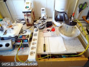
It is time to create a worthy vessel to contain the process better and not stink up the room or cover it in salt residue. Not to mention the zombie
outbreak of corrosion that follows...
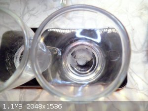
So.....a "huge" beaker shaped glass vase is chosen as the main vessel for the electrolyte. It is cheap, functional and replaceable.
Now we begin to machine the flanges that shall encase the vase from bottom and top, containing all the goodies inside.
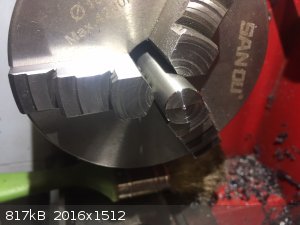
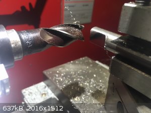
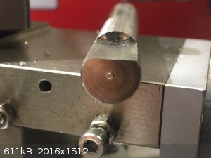
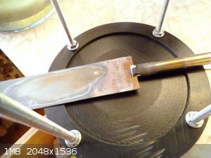
Titanium rod is machined to make the electrode stems....drilled...tapped. Oh it is fun to tap a blind hole in Ti  ! !
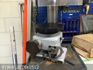 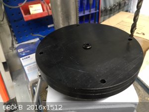    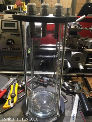
It is taking shape. The flanges are made from PP plastic and grooved to fit the lip of the vase against a gasket and also the bottom is sitting in
recess for correct centering and stability:
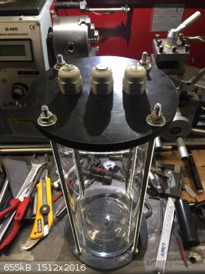 
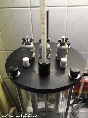
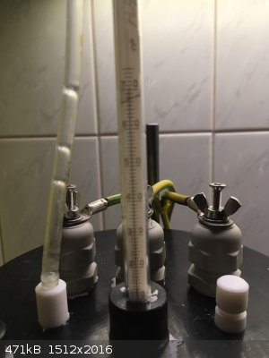
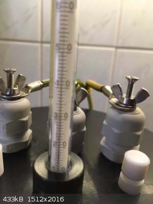
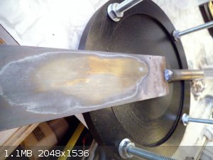
Into the top flange three ports are installed as threaded inserts. For leading away the formed gases....for sampling of electrolyte.....and for
holding a glass thermometer in place. The thermometer port has an adjustable ptfe gasket that gently grabs and seals the outer perimeter of the glass
tube.
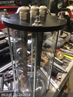
Also proper fasteners are machined and oxide coated to tighten the flanges on the treaded rods:
 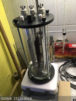 
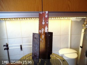
Almost operational:
  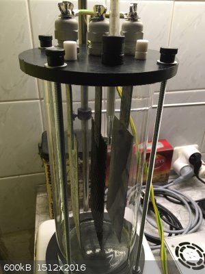
The cell was fitted with a slightly but passionately used set of electrodes (MMO/ Ti) for chlorate synthesis. Just some details to take care of before
we can fill it up and turn the current on.
Gotta direct the gas flow to outside and find/make a gasket to seal the upper flange against the lip of the vase reliably.
That should prevent the gasses and salt spray from exiting anywhere but through the off gas port and make the process much more pleasant for the
surroundings.
Exact science is a figment of imagination.......
|
|
|
DavidJR
National Hazard
Posts: 908
Registered: 1-1-2018
Location: Scotland
Member Is Offline
Mood: Tired
|
|
Nice work!
|
|
|
Ubya
International Hazard
Posts: 1247
Registered: 23-11-2017
Location: Rome-Italy
Member Is Offline
Mood: I'm a maddo scientisto!!!
|
|
Well done.
how many things i could make if i had the space and money (but mostly the space) to have a lathe, a drill press and a few other things.
ps the vase could be wrapped with a heating cord to make a heated cell (for chlorate production)
---------------------------------------------------------------------
feel free to correct my grammar, or any mistakes i make
---------------------------------------------------------------------
|
|
|
markx
National Hazard
Posts: 657
Registered: 7-8-2003
Location: Northern kingdom
Member Is Offline
Mood: Very Jolly
|
|
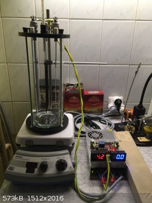
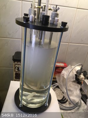
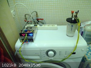
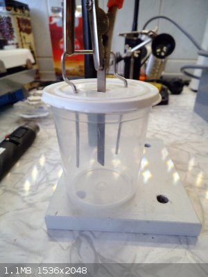
We are in business....and the air is clean 
  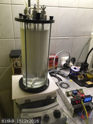
I must fit a plastic vessel under the cell to contain the fluid if the vase should break. I can already see it happening....
Exact science is a figment of imagination.......
|
|
|
markx
National Hazard
Posts: 657
Registered: 7-8-2003
Location: Northern kingdom
Member Is Offline
Mood: Very Jolly
|
|
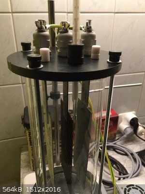
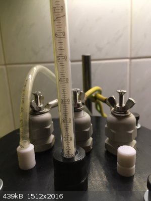
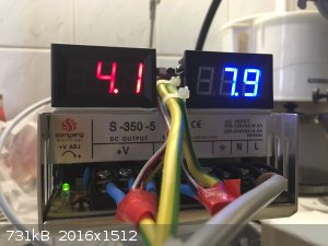
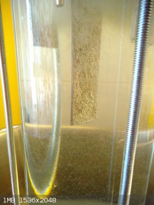
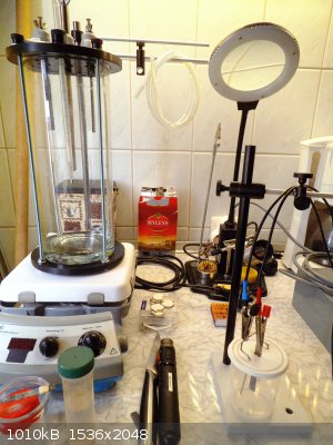
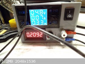
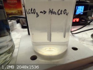
The contraption has been operating with NaCl solution (1kg charge in the vessel) for about 48 hours now....seems to work quite stable, clean and
smooth:
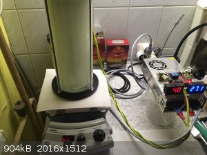
The temperature hovers around 70-75C with no extra cooling or heating and the current is at about 27-30A with 4V applied across the electrodes.
Considerable amount of ClO3- has been generated, assessed by the amount of crystals forming when a liquor sample is mixed with KCl solution. There is
minimal salt creep from the connections...I trust there would be virtually none if the gas exhaust would not have become blocked during the first 12h
of operation. That generated pressure in the cell and forced the liquid through the fittings. I used a too small exhaust tube and tried to lead it
straight out into the cold winter weather.....of course the salt spray and water vapour collected into the tube, were forced out to the cold and there
they assumed it would be a good idea to block the tube and move no further. I kind of thought that would happen, now it's has been proven. So I just
chucked the tube into a bottle of water beside the reactor and called it good. There is virtually no smell at all...just a steady stream of H2 bubbles
coming out of the exhaust tube. That can of course be changed into a radical chlorine stench if I should decide to mess with pH control
But naaah....too much hassle, I just let it run it's course and do nothing of the sort.
Exact science is a figment of imagination.......
|
|
|
markx
National Hazard
Posts: 657
Registered: 7-8-2003
Location: Northern kingdom
Member Is Offline
Mood: Very Jolly
|
|
Finished the first stage of the conversion from Cl- to ClO3- in five days. I suspect it was pretty much done on the fourth day already. Current
started dropping off slightly and temps went up to almost 80C.
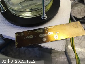
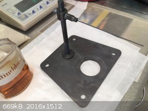
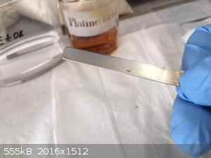
Cell was dismantled cleaned from salt creep and fitted with a homemade Pt coated Ti anode for the next step of conversion from ClO3- to ClO4-
The anode was made by coating a previously sanded and cleaned Ti sheet with a thin layer of hexachloroplatinic acid solution which was thermally
decomposed in a kiln at 350C to yield a coating of metallic Pt. I suspect the decomposition temperature was a bit on the high side, but it worked
nicely.
It's ticking along with a quiet fizzing and the temp holds stable at 50C.
Exact science is a figment of imagination.......
|
|
|
Sulaiman
International Hazard
Posts: 3947
Registered: 8-2-2015
Member Is Offline
|
|
Nice work
I do not like the hazard of many amps-worth of hydrogen gas being continuously discharged,
but I do not have a simple solution to offer.
Generally, electrolysis tends to produce various valuable waste gasses,
(hydrogen, oxygen, chlorine ..)
my puny electrolysis experiments are more for learning than producing,
but you may find a good use for by-products ?
(hydrogenate, oxidise, chlorinate .. something, hydrogen balloon ?)
just a thought.
P.S. Keep a look out for a spare/replacement glass vessel 
[Edited on 24-2-2019 by Sulaiman]
CAUTION : Hobby Chemist, not Professional or even Amateur
|
|
|
markx
National Hazard
Posts: 657
Registered: 7-8-2003
Location: Northern kingdom
Member Is Offline
Mood: Very Jolly
|
|
Quote: Originally posted by Sulaiman  | Nice work
I do not like the hazard of many amps-worth of hydrogen gas being continuously discharged,
but I do not have a simple solution to offer.
Generally, electrolysis tends to produce various valuable waste gasses,
(hydrogen, oxygen, chlorine ..)
my puny electrolysis experiments are more for learning than producing,
but you may find a good use for by-products ?
(hydrogenate, oxidise, chlorinate .. something, hydrogen balloon ?)
just a thought.
P.S. Keep a look out for a spare/replacement glass vessel
[Edited on 24-2-2019 by Sulaiman] |
30A worth of hydrogen shall hardly contribute to a rise in hazard level. Besides I do lead it outside....or at least that was the original intention.
But winter conditions got in the way and since it is more of a trickle than an outpour, I just let it rise to the ceiling and out the cracks.
Gathering and storing it is not a viable practice.....there is not so much, it is contaminated by chlorine, oxygen and probably several more things.
So of little worth in most instances. And it likes to creep out of containment anyways.
According to my practice the glass vessels last a very long time.....that is if one does not break them
But even in that case they are like 3$ a pop in local "walmart" so not to worry. And there are even specimens about three times the volume of this
one available for asocial prices too.
Exact science is a figment of imagination.......
|
|
|
Sulaiman
International Hazard
Posts: 3947
Registered: 8-2-2015
Member Is Offline
|
|
excellent - all covered.
I'm still only at the dreaming stage re. making suitable anodes 
CAUTION : Hobby Chemist, not Professional or even Amateur
|
|
|
markx
National Hazard
Posts: 657
Registered: 7-8-2003
Location: Northern kingdom
Member Is Offline
Mood: Very Jolly
|
|
Aaaargh.....jesus, what a cluster***k!
The whole thing went to hell on a greased rail. From the beginning of the perchlorate stage I felt that the cell was not acting quite the way it
should have. Anode was just holding up too good and I saw no signs of passivation or current dropping within the first five days. Which in all honesty
is not a bad thing, had it not been accompanied by absolutely zero ClO4- forming. So I started to ramp up the voltage to about 5V and all that
happened was a quickly passivating anode which caused a massive polarisation that was high enough to start corroding the anode current collector.
Seems it was composed of a Ti alloy that does not hold up to high anodic potential. The mess of white percipitate on the bottom of the cell is
originating from the current collector.
Also the solution in the cell retained stubbornly the faint green hypochlorite coloration during the whole run time. It is noncharacteristic and shows
that there is no perchlorate being produced. In the stage where perchlorate is starting to form, the cell liquor becomes absolutely crystal clear and
remains so until the end.
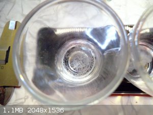
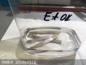
Like thusly:
Platinum plated Ti anode coupled with 316 stainless cathode in a tiny test cell on the way to ClO4- completion. The crystals on the cell bottom are
sodium chlorate that formed during first stage of the run starting from chloride and dropped out due to supersaturation. By the end of the run they
were dissolved and turned to perchlorate.
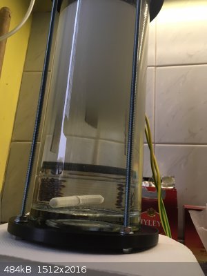
And a bit bigger setup I tried in a 500ml vessel also starting from sodium chloride solution and going happily way up to perch in a single run with
Pt/Ti anode and SS cathode:
I managed to convert in excess of 200g of NaCl directly to perch in the 500ml cell. The solution was supersaturated and the chloride remained on the
bottom until it became converted to chlorate and gradually dissolved. So direct conversion of Cl- > ClO4- can be done in a single run with Pt.
The "ubercell" although failed completely on the perchlorate stage and I can not figure out wether it was the previous conversion to ClO3- by MMO that
poisoned the process....or the unfortunate lesser grade Ti on the anode stem....or the Pt deposition process.......or just plain bad luck.
Anyways I shall recoat the anode with a new Pt layer and perhaps try the direct approach again starting with PT/Ti and a chloride solution. That gig
has worked repatedly, so why not this time.
Exact science is a figment of imagination.......
|
|
|
markx
National Hazard
Posts: 657
Registered: 7-8-2003
Location: Northern kingdom
Member Is Offline
Mood: Very Jolly
|
|
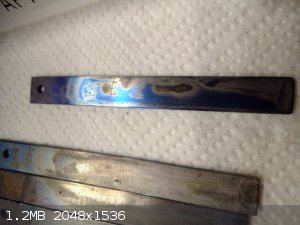
Well....the anode died officially during yesterday. With zero ClO4- having formed in the cell:
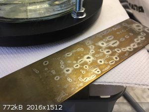
I swapped it out to a new one which I deemed to have failed in the coating process. The surface had been poslished and could not be wetted by the
hexachloroplatinic acid. It formed just some droplets, but I chucked it into the kiln anyway:
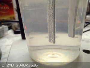
Into the cell it goes:
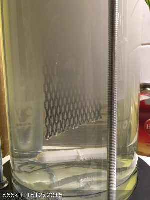
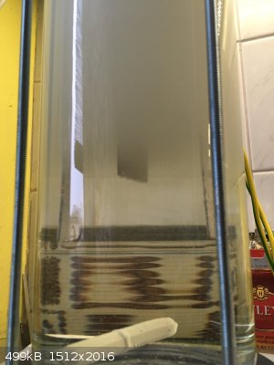
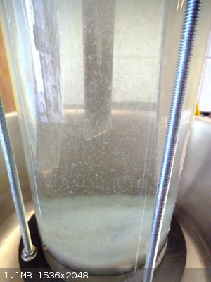
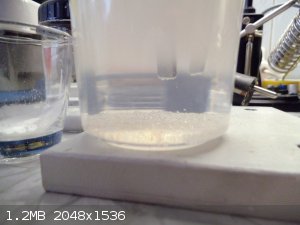
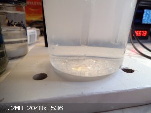
And a miracle happens!! Lo' and behold the visual formation of the heavy perchlorate solution around the anode at the lowest voltage setting of
4,2-4,3V:
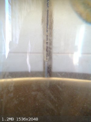 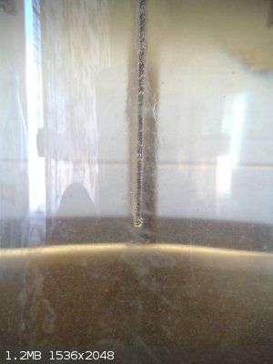 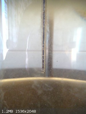
Can you see it? The haze of heavy perchlorate solution distorting the light around the anode surface and sinking down into the cell.....this is so
cool!!
Well at least I hope it is the desired end product bending the light there. And we have definite ozone development going on, it can clearly be
detected in the off gas flow.
Exact science is a figment of imagination.......
|
|
|
markx
National Hazard
Posts: 657
Registered: 7-8-2003
Location: Northern kingdom
Member Is Offline
Mood: Very Jolly
|
|
I discontinued the endless agony of waiting for the endproduct to form. There is clearly some kind of a pollutant in the current cell liqour batch
that effectively prevents anything above ClO3- from forming.
The brief successful formation of heavy product solution that happened when I switched the anode, disappeared gradually after half hour of operation
and everything went back to mere electrolysis of water as much as I could notice. There was no more ozone generation and no density changes around
anode.
I tried to switch off the cell and let it cool down to room temperature to see if it was perhaps the lower temp that triggered the brief formation of
perhchlorate. The cell did cool down to 20C during the previous anode change. Well, no success.
I tried to dial up and down the applied voltage to determine if there was a critical polarisation level which the anode has to reach before it can
start forming pechlorate (well obviously there is ) but to no avail. Even
applying 10V across the cell would not change things.
I just gave up on that run and removed the cell contents which have a clearly greenish blue discoloration to them. Also there is a strong presence of
free chlorine and hypochlorite, which should both be pretty much gone at the stage where perchlorate formation begins. At least previous successful
small scale experiments have shown it to be this way.
Most of the discoloration surely originates from the anode stem that could not resist the urge to dissolve, but I'm not completely sure it is the only
culprit.
I also suspected that perhaps the anode surface texture was unsuitable. Older german literature states that only smooth Pt is suitable for
electrosynthesis of perchlorate and plated or deposited Pt fails to do so, as it does not reach the critical polarisation level due to the uneven
surface allowing too much charge transfer.
This may be the case, but anodes that I used in previous small scale experiments were pepared in the same way.....from the same source of Pt ....on
exacly the same Ti substrate material. And they worked pretty darn good for a disposable superthin layer unit. In fact the first anode that died in
this cell was deposited on the same piece of Ti I used to drive the 500ml cell to a complete "endsieg".
The only difference was that first stage conversion was performed by MMO this time and the anode stem in perhlorate stage was made from inferior Ti
grade.
I'm kind of reluctant to accuse the MMO, so this leaves the contamination originating from the inferior anode stem. Mostly it should be Ti, Fe, Al,
and V compounds that entered the electrolyte and perhaps found a way to fight my cause?
Exact science is a figment of imagination.......
|
|
|
markx
National Hazard
Posts: 657
Registered: 7-8-2003
Location: Northern kingdom
Member Is Offline
Mood: Very Jolly
|
|
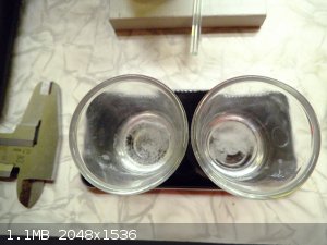
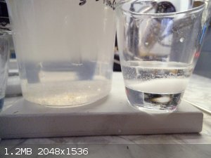
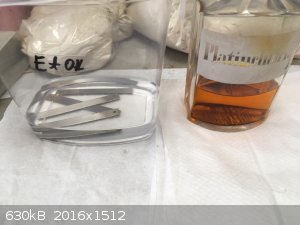
I'm preparing a small test cell to find out if my previous problem was electrolyte contamination related or there is some other factor at play:
Two NaClO3 solutions side by side:
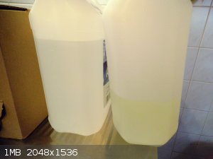
The yellow one being the last problematic batch with metallic contaminants that originated from the low grade Ti shank.
Some Pb02 anodes from previous experimentation. They do shed their skin quickly in a perchlorate cell, but the Pt coat underneath shall
prevail for quite some time. So I'll try one of these in the test cell:
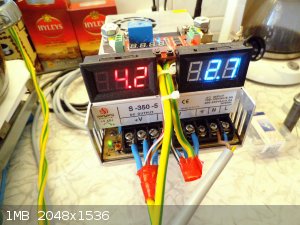
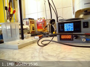
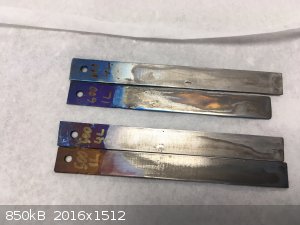
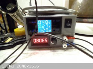
Oh yeah.....for those who, like myself, think that constant current mode for a perchlorate cell sounds like a good idea:
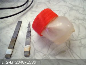 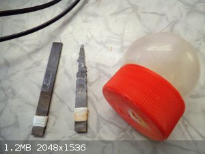
That's what's gonna happen when the power converter forces a constant current through a cell with a gradually failing anode....everything overheats,
Grade 1 Ti starts to dissolve (take a look at that anode carcass on the right), cell boils dry and if one is especially lucky, bursts into flames.
[Edited on 10-3-2019 by markx]
Exact science is a figment of imagination.......
|
|
|
markx
National Hazard
Posts: 657
Registered: 7-8-2003
Location: Northern kingdom
Member Is Offline
Mood: Very Jolly
|
|
Quite interesting read:
Attachment: 617569.pdf (976kB)
This file has been downloaded 617 times
Seems that Pt surface needs to obtain a certain configuration for appreciable current efficacy of the process. Hence previous application history of
the anode is of importance. Prepolarisation prior to perchlorate synthesis seems to have an effect on current efficacy according to the article.
I've seen similar effects when I tried the process with KClO3, due to KClO4 being mostly insoluble the formation process can be
observed visually at the Pt coated anode: the perchlorate formation was always delayed, sometimes for days and then started abruptly. Sometimes on
it's own and sometimes due to a rise in applied voltage across the cell.
I figured this might be due to a certain balance of compounds building up in the electrolyte, but it might just as well be that the anode surface
takes it's sweet time to reach a suitable condition.
The deposited Pt is not in a condition that can be called "smooth" in an electrochemical sense. Also there is erosion taking place and it leads to an
electropolishing effect, where the protruding areas shall erode away first, making the anode surface smoother. Perhaps it is required to etch away
part of the Pt by the process before the surface becomes smooth enough to allow for a successful perhclorate formation to begin.
Exact science is a figment of imagination.......
|
|
|
phlogiston
International Hazard
Posts: 1383
Registered: 26-4-2008
Location: Neon Thorium Erbium Lanthanum Neodymium Sulphur
Member Is Offline
Mood: pyrophoric
|
|
Interesting, the processes taking place at the anode are apparently a lot more complicated than I imagined.
Regarding using a constant current supply: there are also supplies that allow you to program both a current and a voltage limit. They deliver either
constant-current or constant voltage, whichever is limiting.
It could be used to prevent overheating in the failure mode that you describe, because the increased resistance will lead the power supply to increase
its output voltage to maintain current, untill it hits the maximum voltage setting. At that point it becomes a constant voltage supply.
-----
"If a rocket goes up, who cares where it comes down, that's not my concern said Wernher von Braun" - Tom Lehrer |
|
|
markx
National Hazard
Posts: 657
Registered: 7-8-2003
Location: Northern kingdom
Member Is Offline
Mood: Very Jolly
|
|
Yay!! I have definite and massive perchlorate formation going on in the small test cell. Again the formation was delayed roughly by 36 hours. During
that timeframe I could not detect any perchlorate type of deposition (sudden and ultrafine) with interaction upon KCl solution. But today I get the
characteristic fine deposition of cristals and there is quite a lot.
I used one of the Ti/Pt substrate lead dioxide anodes and NaClO3 solution from the clean container without the contaminants. This
NaClO3 batch was also formed by the same MMO anode, so I can rule out the chlorate conversion stage of being the source of problems for
further conversion.
The cell operates at about 5V and between 1-1,5A of current. The active anode surface area is roughly 8cm2, so the current density hovers
around below 2kA/m2. This be on the low side for top efficacy according to literature, but I hope to stretch more life out of the poor
thing this way. It has deteriorated rather healthily already.....the PbO2 skin fell off during the first hours, after which I filtered the
solution to extract the lead dioxide particles. Now I can see also the Pt coating giving up in areas of greater current density. It does not so much
passivate, but just dissolves away from the surface. It remains in the solution bound up by some form of a colorless complex. Letting the perchlorate
solution stand for weeks after synthesis gives slow rise to a greyish slimy precipitate from the clear solution. I suspect this blob contains the
platinum or at least part of it. Might try a regeneration with some aqua regia if I succeed to extract the precipitate at some point. It is really
fine and tends to seep through filters.
This type of electrode deterioration is to be expected, but really I see that as a minor inconvenience. The small stock of hexachloroplatinic solution
I have got is more than enough to cover a lifetime worth of Ti substrate. One literally needs a single drop to create an anode of the size I have in
the small cell now.
About the CC operation mode.....yes the meltdown was caused by lack of failsafes. There sure are power supplies that have the option to preprogram all
kinds of limitations, in fact I think the SEPIC converter I used "sort of" has this option available intrinsically, but I found no convenient way to
check where the limitation regarding voltage up conversion kicks in at the time, so I just let er rip until the bitter end.
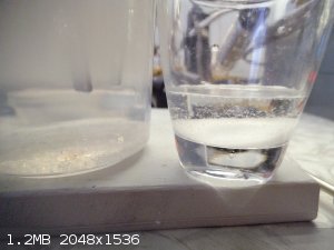
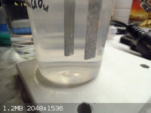
Side by side differences in the formation of KClO3 and KClO4 upon the action of KCl solution on cell liquors:
The right side "vial" contains a sample from the electrolyte of the small perchlorate cell and it displays the characteristic formation of
KClO4 in a dense and fine layer of cristals forming instantaneously on the liquid surface where the KCl solution drop hits.
The left side "vial" contains the starting solution of NaClO3 and it displays the formation of KClO3 in a slower reaction that
produces scattered coarse cristals in the solution. Just a simple qualitative method to assess if an appreciable amount of pechlorate has arisen in
the cell...
[Edited on 12-3-2019 by markx]
Exact science is a figment of imagination.......
|
|
|
markx
National Hazard
Posts: 657
Registered: 7-8-2003
Location: Northern kingdom
Member Is Offline
Mood: Very Jolly
|
|
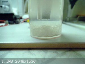
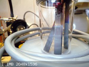
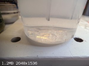
The small 150ml cell has been ticking along for a week now and as far as I can see it is about as good as it will get. The current flow effectively
and sharply drops to a few dozen milliamps if I one lowers the cell voltage to 3,5V or below.
The solution has obtained the characteristic "clarity" associated with last stages of perchlorate conversion from NaClO3 and there already is visible
percipitation of the product at the bottom of the cell where temperature is lower. Interestingly enough I observed basically no ozone during the
whole conversion run. And the anode is still very much alive. A rather different display of events compared to what I have observed so
far....successful though.
On the right one can observe the amount of KClO4 that percipitated from 1ml sample of the cell liqour. The supernatant liquid (about 7ml)
is water. It was added to loosen up the crystals and dissolve any chlorate or chloride that may have been present.
Exact science is a figment of imagination.......
|
|
|
Sulaiman
International Hazard
Posts: 3947
Registered: 8-2-2015
Member Is Offline
|
|
In one hour you would generate 30A x 3600s / (2 x[Faraday's constant]) = 0.56 moles = 12.5 litres of H2
As you wrote, not much of a hazard outside or in a well ventilated space,
but as hydrogen can detonate in hydrogen:air ratios of 1:4 to 1:59,
there is a real risk of explosion (not just fire) in a poorly ventilated environment.
e.g. worst case;
running overnight, 10 hours x 12.5 litres x 59 = total detonation in a
6' x 6' x6' room,
releasing 475 kJ/mol x 5.6 mol = 2.66x10⁶ Joules - in milliseconds
(theoretically enough to briefly power Doc Brown's Flux Capacitor)
Just thought I'd emphasise this hazard for the benefit of less experienced chemists.
(explosions due to lead-acid battery over-charging are even now a significant risk requiring multiple mitigation implementations)
CAUTION : Hobby Chemist, not Professional or even Amateur
|
|
|
markx
National Hazard
Posts: 657
Registered: 7-8-2003
Location: Northern kingdom
Member Is Offline
Mood: Very Jolly
|
|
If the cubicle one performs the synthesis in is "tighter than a duck's butt" then for sure it would not be a good idea to play around with fire in
there
A rather more serious hazard which actually tickles the hair at the back of my neck a bit is the gas mix contained in the top part of the cell above
the liquid level. If under unfavorable conditions the oxygen evolution on anode is increased, then a rather nicely detonable mix shall be contained in
that volume. Even more startling is the ozone evolution stage that tends to happen at the end of perchlorate conversion stages. The current collectors
run through that volume of gas. If they are undersized for the amount of current that they have to commute or there is a bad connection in
there.....overheating.....bang.
I have not actually heard of such a thing happening regarding electrosynthesis of the compounds covered here, but the possibility is there. And I know
from first hand experience that even moderate amounts of hydrogen mixtures with that composition can do a lot of bad things if confined in a reactor.
Exact science is a figment of imagination.......
|
|
|
markx
National Hazard
Posts: 657
Registered: 7-8-2003
Location: Northern kingdom
Member Is Offline
Mood: Very Jolly
|
|
I'm performing a second run with the small cell and a set of anodes I made at different Pt deposition temperatures (pyrolysis temperatures more
precisely).
The cell has been running for 6 days now and there are massive sodium chlorate crystals on the bottom. They tend to drop out in an intermediate stage
of the conversion where both perchlorate and chlorate are present in a healthy concentration. At the end of the conversion they dissolve again.
The set of small anodes I made to investigate the effect of Pt deposition temperature on the longevity of the anode:
 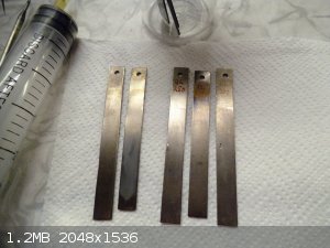
I varied the temperature from 250C - 400C and also varied the number of coats applied : either 1 or 4 coats of Pt.
The procedure that constituted one coating of Pt applied, was as follows:
Grade 1 Ti strips that were previously sanded clean with 400 grit wet dry paper and stored under ethyl alcohol were dried and coated with
hexachloroplatinic acid solution. They were just wiped with a drop of the solution and as much as remained on the surface in a uniform manner was left
there. Excess was removed. The electrode was then placed on a fixture and into a preheated temperature controlled laboratoory kiln for 10 minutes.
After the 10 minutes were up, the electrode was removed from kiln and cooled down. It was flushed with water and wiped with ethyl alcohol to remove
any loose Pt particles. After that a "coating" was deemed to have been applied. The procedure was repeated at the same temperature to apply multiple
coats.
The set I prepared was as follows:
250C 1 coat
250C 4 coats
300C 1 coat
300C 4 coats
350C 4 coats
400C 1 coat
The cell was loaded with 150ml of NaClO3 solution and electrolysis was commenced at 4,3-4,6V and a current of 0,7-0,8A. The anodes have a
surface area of about 8cm2. So the current density is in the range of 100mA/cm2. Abit on the low side, but otherwise the cell
temperature creeps up too far.
I started off the conversion run with 250C 1 coat anode: it was not durable and perished wihin the first 3 hours of operation due to passivation.
After that the 400C 1 coat anode was put to use and it showed markedly better resistance against passivation. It persisted for four days in the cell,
before noticeable passivation occurred. For practical purposes I could have stretched one more day out that one, but I opted to change it to 350C 4
coats specimen.
That one has been bubbling away for 2 days now and for all intentive purposes does not yet show noticeable passivation.
Seems that it makes sense to try even higher Pt deposition temperatures....say in the range of up to 800C. I was afraid that higher temperatures would
increase the formation of oxide coating underneath the Pt layer and render the anode less effective, but current results show a reversed trend. At
least up to a certain point I guess.
Exact science is a figment of imagination.......
|
|
|
MrHomeScientist
International Hazard
Posts: 1806
Registered: 24-10-2010
Location: Flerovium
Member Is Offline
Mood: No Mood
|
|
This is fantastic work; really great to read. Your cell construction looks very nice, and makes me yearn even more for a shop with those sorts of
tools. Out of curiosity, what is the end use for all this perchlorate?
|
|
|
Loptr
International Hazard
Posts: 1348
Registered: 20-5-2014
Location: USA
Member Is Offline
Mood: Grateful
|
|
Wow, I can't believe I missed this thread. Very nice construction!
"Question everything generally thought to be obvious." - Dieter Rams
|
|
|
markx
National Hazard
Posts: 657
Registered: 7-8-2003
Location: Northern kingdom
Member Is Offline
Mood: Very Jolly
|
|
| Quote: Originally posted by MrHomeScientist | | This is fantastic work; really great to read. Your cell construction looks very nice, and makes me yearn even more for a shop with those sorts of
tools. Out of curiosity, what is the end use for all this perchlorate? |
Thanks for the kind words! Really, there is no "end use" of any particular
purpose for this project. Just doing it to expand the extent of my knowledge sphere. Perhaps I'll try some visco compositions based on perchlorate to
yield a clean burning fuse without much soot and dross. As a matter of fact the accumulation of product from the "ubercell" would be a real problem.
Exact science is a figment of imagination.......
|
|
|
MrHomeScientist
International Hazard
Posts: 1806
Registered: 24-10-2010
Location: Flerovium
Member Is Offline
Mood: No Mood
|
|
I can definitely get on board with that! Nothing wrong with doing things for fun and learning.
I find it interesting that there are a ton of people out there making chlorate and perchlorate cells to create mountains of these chemicals, but I
rarely see what anyone's making them for. Pyrotechnics, I guess?
|
|
|
markx
National Hazard
Posts: 657
Registered: 7-8-2003
Location: Northern kingdom
Member Is Offline
Mood: Very Jolly
|
|
Been tinkering with the small cell and higher deposition temperatures involved in the anode making while I wait for my grade 1 Ti rod to arrive, so I
can revive the ubercell.
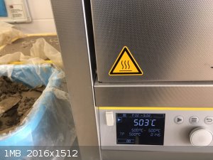
I went ut to 600C for the Pt deposition temperature and prepared a set to test out how the coats perform.
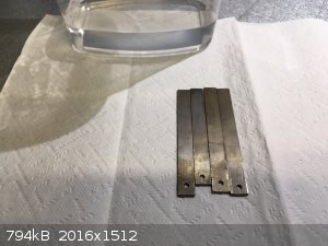
Cleaning of spent anode substrates and storage under alcohol prior to recoat
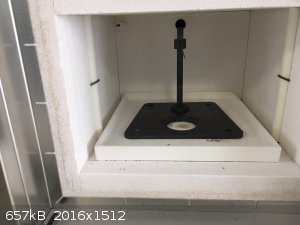 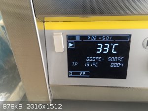 
Heating up the kiln with the stand to hang the anodes from in it.
 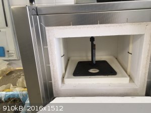 
Applying a thin layer of hexachloroplatinic solution on substrate. Into the kiln for 10min and out they come again...
Final set of 500C 1 coat, 500C 4 coat and the same for 600C.
I did start the testing with the 600C 1 coat anode to see how it comapres to the 400C counterpart that endured for four days before giving up the
ghost.
All conditions being reasonably repeateable the 600C specimen endured for 6 days and some exta hours before passivation set in. Not bad....the 400C
counterpart stretched 4 days of life out of it. So a day for every 100C raise in deposition temperature
Passivation...only a few spots are seen to bubble on the anode. But the PT coating seems to be mostly there, just it has a TiO2 coat underneath that
prevents it from conducting.
600C 4 coats anode goes in and the surface conducts evenly. In fact I had to dial down the voltage to 4,5V as the cell heated up and current creeped
above 1,2A at 4,8V. This is too much for the little plastic pot and it shall boil up. Now the 600C 4coat has been ticking along for 3 days at 0,8-0,9A
and everything is stable.
The 350C 4 coat anode that I used to finalize the previous conversion run was working without any signs of passivation for 8 days until the chlorate
became compeltely depleted and then it abruptly and totally passivated. It happened within one hour of operation and the deterioration was
devastatingly complete. It further cements my conclusion that most of the damage to the anode shall happen at the last stages of conversion.
But for the life of me I have not noticed even a hint of real ozone production from the current small cell....that is strange. Because I remember the
small cell that I ran with similar anodes (made with not precicely controlled deposition temperature) previously, produced so much ozone that it one
could smell it two rooms away.
Exact science is a figment of imagination.......
|
|
|
| Pages:
1
2 |


