| Pages:
1
2 |
mc68k
Harmless

Posts: 24
Registered: 26-10-2023
Location: Durham, NC, USA
Member Is Offline
|
|
Building a Chemputer
I was inspired by a couple articles that described the mechanics of an automated organic synthesis system [1]. But the real gold is the supplementary
data [2] which describes all the technical details of the system. The lead, L. Cronin and his lab published several papers on the system, it's
"synthesis language", and various adaptations (Grignard reactions, automatic chemical discovery and characterization, etc).
They later named it "The Chemputer".
Since I'm interested in chemistry, robotics, automation, and software - this is right up my alley!
My goal is to replicate a portion of the system, enough to 'execute' one of their synthesis scripts. Although I'd be happy just automating the
manufacture of any non-trivial material.
[1] Organic synthesis in a modular robotic system driven by a chemical programming language, L. Cronin (also attached)
[2] Supplemental report from [1]
Attachment: Organic synthesis in a modular robotic system driven by a chemical programming language.pdf (2.2MB)
This file has been downloaded 150 times
move.w %0x2700,sr
movem.l d0-d7/a0-a6,-(a7)
lea science,a0
jsr madness
|
|
|
mc68k
Harmless
Posts: 24
Registered: 26-10-2023
Location: Durham, NC, USA
Member Is Offline
|
|
Current progress:
I scrounged up some control components and ordered some parts to put together a simple liquid-transfer system, which will be the 'backbone' of the
chemputer.
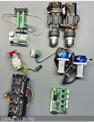
Arduino Uno (upper left)
This will be the main driver/controller, it currently drives the peristaltic pumps but will eventually also receive commands from the PC (eg. transfer
10 mL from container A to container B).
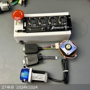
Geckodrive G540 (lower left)
This is a 4-axis stepper driver. I had it left over from another project.
Peristaltic Pumps (middle-right)
These will perform the liquid transfers between flasks.
Stream Selectors (top right)
I believe these are used in HPLC machines for sample injection? Found them for $35 on eBay. They are 6-port selectors, so I can address a total of
12 flasks using them. The have steppers, gearboxes, and optical rotation locators. Score!
Currently having some issues finding compatible fittings for it though. 
Ender 2 Mainboard (bottom right)
From a mainboard upgrade on my 3D printer. This has another 4-axis of stepper control and already supports a control language (gcode).
move.w %0x2700,sr
movem.l d0-d7/a0-a6,-(a7)
lea science,a0
jsr madness
|
|
|
fx-991ex
Hazard to Self
Posts: 71
Registered: 20-5-2023
Member Is Offline
|
|
will be interesting, electronics(repairs, circuit/pcb design/assembly) and programming(website/microcontroller/software, usually all 3 together) been
my main hobby for 20+ years. Am very good in this domain  . .
Ill see if i can help.
[Edited on 26-10-2023 by fx-991ex]
[Edited on 26-10-2023 by fx-991ex]
|
|
|
j_sum1
Administrator
Posts: 6230
Registered: 4-10-2014
Location: Unmoved
Member Is Offline
Mood: Organised
|
|
Wow. What an ambitious project. Really interesting and potentially very useful.
Keep us posted on how it goes.
|
|
|
Texium
Administrator
Posts: 4517
Registered: 11-1-2014
Location: Salt Lake City
Member Is Offline
Mood: PhD candidate!
|
|
Those HPLC injectors tend to have very tiny liquid capacities, typically designed for transferring only tens of microliters at a time. I’m not
optimistic that they would be effective for routing mL scale volumes on a short timescale.
Overall though, interesting ideas. I think such a system would truly shine in programming slow additions of reagents. Nobody wants to sit around with
a syringe adding things dropwise for an hour, and sure, syringe pumps exist, but they are very bulky and annoying to set up. Not even worth it most of
the time.
|
|
|
Texium
|
Thread Moved
26-10-2023 at 20:08 |
mc68k
Harmless
Posts: 24
Registered: 26-10-2023
Location: Durham, NC, USA
Member Is Offline
|
|
fx-991ex:
Yes! It's a neat mix of skills and interests.
I could use help with hardware selection (single-board computers, sensors, etc), since I'm unfamiliar with most of the components being used.
I think Arduino is a good starting point, but each board can only manage a few components due to the number of inputs/outputs required. For example,
the selection valves require 6 pins: DIR, STEP, I1, I2, I3, I4 (optical position sensor inputs). This means each Arduino can really only control
about two components.
The chemputer is built from modular single-board computer elements, each controlling just one of the lab components. This simplifies the scale-up
since they just plug all of the computing elements into an ethernet switch and control the whole thing from one PC. Definitely the right direction,
but out of my current scope (but if you wanted to look into that...) 
j_sum1:
Thanks! I hope to get far enough along to do some interesting chemistry, even if replicating their entire system is WAY out of scope.
Texium:
Sadly, I am aware of the discrepancy, but this was the best I could find for the moment. The chemputer valves are IDEX V-320 which use 1/8" OD tubing (easily transporting 10s of mL), while the ones I have are Rheodyne PD725-125 which use thick-wall 1/16" OD tubing and are designed for high-pressure sample injection (generally measured in uL as you
mentioned).
Not too concerned since the valves I purchased also have steppers and sensors which could drive some other valve if the liquid throughput from these
is too low.
Interesting note; in another paper [1], the same lab uses 1/16" tubing throughout in order to fit with and automate an HPLC alongside the chemputer.
More bits and Dr.Bobs:
Reading through the chemputer papers I noticed that they had to use several custom-designed glass components, specifically a jacketed filtration
module and liquid-liquid separation module, in order to achieve automation control over the reactions.
While digging around for other information about their designs, I found a paper by some of the other lab members. One interesting methodology
"adjacent" to the chemputer work is 3D-printed custom reaction vessels [2].
This solves the problem of how I will gain access to the specialized flask designs used in the chemputer! Printing reaction vessels using
Polypropylene filament appears to work just fine for many solvents and reaction temperatures. However, it does limit the maximum temperature of
reactions to 130 C, and even there only for short durations.
What I found particularly interesting in this paper is the use of glass frit filters and hydrophobic membranes installed during the 3D print cycle
such that they are bonded into the reaction vessels.
Dr.Bob was able to supply some hydrophobic membranes that look like they might work for this purpose.
[1] Digitizing Chemical Discovery with a Bayesian Explorer for Interpreting Reactivity Data (see supplemental data)
[2] 3D designed and printed chemical generators for on demand reagent synthesis
move.w %0x2700,sr
movem.l d0-d7/a0-a6,-(a7)
lea science,a0
jsr madness
|
|
|
mc68k
Harmless
Posts: 24
Registered: 26-10-2023
Location: Durham, NC, USA
Member Is Offline
|
|
The chemputer is made up of a few physical modules, each of which performs one of the common bench synthesis steps.
- Liquid transfer
- Mixing under temperature control
- Liquid/liquid separation
- Filtration
- Solvent evaporation
Liquid Transfer
This is the 'backbone' of the system, transferring liquids from reagent jars into flasks, filters, and waste. The chemputer uses syringe pumps
connected to multi-port selection valves. Both the syringe pump and selection valve modules are custom-designed by the lab.
Instead of syringe pumps I chose peristaltic pumps based on a few factors:
- they're cheap
- pump forward and backward
- pump precise amounts of fluid
- don't need to be primed
- can be used in future projects
Multi-port selection valves that are chemical resistant are not common components outside the lab. The industrial version would be a custom manifold
of solenoid valves that are immensely more bulky.
I've looked for 3D-printable selection valves, but none are of acceptable quality for this project.
I'll have to continue searching eBay for additional valves as the project progresses. I currently have 3, which should be enough to get started.
Mixing under Temperature Control
In the papers, this module is called the Reactor. Early versions of the chemputer use a RBF on a custom aluminum block over a computer-controlled
hotplate/stirrer. It has an air-cooled condenser for refluxing and a thermometer to control temperature.
Later versions are described as using an aluminum block with internal piping which circulates fluid from external heater/chiller to control reaction
temperature. They switched to using an overhead stirrer, and the reflux column is a standard glass column fed from a water chiller.
I do have a computer-readable thermometer and a non-automated hotplate/stirrer. I could set the hotplate on "high" and use a on/off controller to
pulse it to control temperature, but that would mean stirring is also pulsed.
Another option is to get a recirculating chiller/heater, then 3D print an equivalent reaction vessel with a water jacket. Adding computer control to
the chiller/heater would enable precise reaction temperatures.
Liquid/liquid separation
The authors were not entirely happy with their liquid separator, a modified sep funnel with a conductivity sensor inline with the bottom port. It is
less than ideal because it exposes stainless steel tubes to the reactants, but they did report good/precise separations.
I'm looking into continuous liquid-liquid separators using hydrophobic membranes[1]. This would significantly simplify the separation & washing
steps and reduce the needed infrastructure.
Filtration
The filtration module is a complex one. It's a custom-jacketed Büchner funnel with a stirrer. This allows them to fill the funnel with the reaction
mixture, cool it to crystalize the product, vacuum filter the liquid, wash with new solvents, and finally vacuum dry the final product.
I will likely just 3D print an equivalent module and install a glass fit in the bottom. If I do get a recirculating heater/chiller, this module will
also benefit from it.
Solvent Evaporation
I'm unlikely to get around to automating a roto-vap, so the solvent evaporation step will have to be replaced with some kind of distillation.
Yet to be researched.
Current Progress:
- Got the peristaltic pumps working properly - not overheating or stuttering instead of pumping.
- Ordered fittings for the selection valves
- Wrote Arduino program to control a pump and receive serial communications which sets the speed of the pump
[1] zaiput.com
move.w %0x2700,sr
movem.l d0-d7/a0-a6,-(a7)
lea science,a0
jsr madness
|
|
|
sceptic
Harmless
Posts: 49
Registered: 7-6-2022
Location: Southern Africa
Member Is Offline
|
|
What kind of filament are you planning to use? I think it will be hard to find one that's commonly available but also resistant to acids, bases,
oxidizers, etc.
|
|
|
mc68k
Harmless
Posts: 24
Registered: 26-10-2023
Location: Durham, NC, USA
Member Is Offline
|
|
Quote: Originally posted by sceptic  | | What kind of filament are you planning to use? I think it will be hard to find one that's commonly available but also resistant to acids, bases,
oxidizers, etc. |
sceptic, check out the paper I referenced above about 3D printed cartridges:
https://doi.org/10.1038/s41467-019-13328-6
Current Progress:
- Writing OpenSCAD scripts to generate various cartridge shapes/sizes
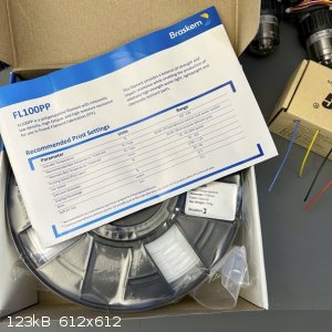
- Got PP filament to test
- Making permanent wiring harnesses for the peristaltic pumps
move.w %0x2700,sr
movem.l d0-d7/a0-a6,-(a7)
lea science,a0
jsr madness
|
|
|
sceptic
Harmless
Posts: 49
Registered: 7-6-2022
Location: Southern Africa
Member Is Offline
|
|
Oops! I didn't notice that section of your post.
|
|
|
Rainwater
National Hazard
Posts: 800
Registered: 22-12-2021
Member Is Offline
Mood: indisposition to activity
|
|
I read, readed. @&>/. I hate english, we got 45000 words and i sware half are the same thing.
I red those papers.
Seams like a industry standard, simply reinvented.
They may not even know there, their.... they are redesigning the wheel.
Their using the standard top down design approach.
They want to use a specific programing language called X.
As a programmer, thats fancy talk for a script.
They want language X to translate via compiler into a maching/lower level languages.
Fancy talk for an interpreter.
They want to write something like
| Code: |
// NaOH + HCl = NaCl + H2O
// list reagents and assign to dispencer
// Reagents.add( name, molarity, container)
Reagents.add("NaOH", 1, 0)
Reagents.add("HCl", 12, 1)

//set reaction conditions
Reaction.mixSpeed( 300 ) //how long to take to add all of the reagents in seconds
Reaction.stirring(100) //rpm
Reaction.tempature(50) //hotplate temp

//set Stoichiometry
//Reaction.add(name, mols)
Reaction.add("NaOH", 1)
Reaction.add("HCl", 1)

//start the procedures
{
    Start()
}(...){ print("we had an error") }

print("its all good boss")
|
Using a moduler design you can develop a list of simple commands for each module.
Designing a single controller to run every module or designing modules that talk to the controller and run their self is a hardware decision.
Your programming should not care either way about how this functions.
From the code snippet above, you should have the reactor object do all the math us lazy amateurs dont want to do.
How many mL of this, to that, and how slowly to add each to the mix.
You should also set up limits and inventory. You dont want to add 100ml of solution into the reactor when you only have 6 left in the reagent bottle
Or worse, add 300ml to a flask thats only 100ml big.
All the simple stuff you may want to control should be listed
Draw up some block diagrams and move things around.
Section off task to different modules in your code.
Each modules job should be short and clear. For example.
The main controler should not worrie about starting and stopping a motor, measuring time to dispence just the right amount.
The main controler says, "dispence 2ml of reagent 0".
The dispencing module worries about the details of how to do that.
Your controller module shouldnt even care how it communicated with the dispencer module.
Either by setting a flag for another section of your code to execute, or sending a message by wire or across the world. Your controller should not
care how output is handled.
Same thing for input. File, gui, ip/tcp or modbus connection. Shouldn't matter
Starting out with this mindset will make your programs much easier to manage as this project evolves.
Something like this, start writing doc files, explane how it works from a user prospective before you write the first line of code. Then, you have a
template to build your programs around.
For the pumps an L298N based H bridge development module would be perfect for your driving any 5-32v dc motor @2 amps per channel.
Positive feedback could be added with some beam break sensors (ADA2167) for more accurate despencing.
An hiletgo STM8S103F3P6 dev board could run 2 L298n boards, with 4 feedback sensors for less than $15 bucks + the motors.
Setup uart for serial communication via usb and just plug everything into a usb hub.
There's you power supply for the controllers and all interconnections in 1 cable. From the factory.
Can control everything from a pc like that.
Edit. Sorry, just double checked the specs. Have to use a logic level shifter or a different mcu board. That one is 3.3v and the h bridge requires 5v
logic.
[Edited on 3-11-2023 by Rainwater]
Nano Board V3.0 ATmega328P amazon has a 6 pack for 30 bucks. Same form factor, 5v output. Would be able to run 4 pumps or act as an interface between
usb and the Rheodyne PD725-125. I could not find the model # listed, but all their controllers are "contact for pricing" which is never a good thing.
They do provide a high resolution picture . Suckers
They are using they 3977sedt stepper motor but are missing reverse input protection to the chip and very weak Vcc ripple filtering.
Just means they sell more boards when one is connected wrong. Probley spec a high dollar psu to drive it that has all the filtering included.
Datasheet attached
[Edited on 3-11-2023 by Rainwater]
Attachment: 3977.PDF (569kB)
This file has been downloaded 94 times
"You can't do that" - challenge accepted
|
|
|
DXFlatline
Harmless
Posts: 4
Registered: 18-9-2023
Member Is Offline
|
|
IBM has RoboRXN. Infact you can feed it pretty standard synthesis procedure text like "1 mole of X was refluxed for 6 hours at 180C" and AI takes care
of the rest
|
|
|
mc68k
Harmless
Posts: 24
Registered: 26-10-2023
Location: Durham, NC, USA
Member Is Offline
|
|
DXFlatline,
That sounds similar to what they've done with the chemputer. They taught it to read published literature and compile the experimental section into a
script that can reproduce the experiment using the chemputer.
Rainwater,
Yes! Sounds like we're on the same wavelength here. I'll probably use Javascript or Python as the scripting language on the PC side.
Thanks for the recommendations on driver boards, definitely something I'll check out as I expand. The G540 will be fine for now, but I do want to
grow beyond 4 programmable components.
The USB hub is a good idea too - I was looking at stacking an Ethernet shield, PT100 temperature sensor shield, and stepper driver shield on top of
the base Arduino. Ethernet is almost half the total price of that stack so if the USB hub works, that would be a significant savings.
Current Progress:
- Printed a box for the G540 and its mess of wiring
- Received the fittings for the valves
- Tested valve throughput using a 30 mL syringe, I could run all 30 mL through in less than 30 sec with just hand pressure. That's plenty of
throughput for this project (I'm targeting reactor volumes in the 10s of mL).
move.w %0x2700,sr
movem.l d0-d7/a0-a6,-(a7)
lea science,a0
jsr madness
|
|
|
Rainwater
National Hazard
Posts: 800
Registered: 22-12-2021
Member Is Offline
Mood: indisposition to activity
|
|
pt100 can be read directly from any analog pin.
Simple circuit connects like so
Vcc > pt100 > 150ohm resistor > Gnd
Connect the analog pin to the node connecting the sensor to the resistor.
No coffee yet. Dont trust my math
Vout = (Vcc * Rtd) / (Rtd + R1)
Flip the math to solve for Rtd is
Rtd = -1 * [ (Vout * R1) / (Vout - Vcc) ]
Pt100 standard thermal coefficient is
3.85×10⁻³ /c
Getting a shield should include overcurrent protection and a strong low pass filter. For a 1off just buy it. When you go into mass production, print
it
Remimber the self heating problem P=E²/R
Usually solved by using a resistor with 5-10 times the required thermal dissipation.
Read the datasheet for your pt100 and adjust R1 accordingly
Edit
I recommended the usb as a convenient source of power and coms.
Wanting more than 4 motors on 1 control unit, will increase expense and complexity
The price point is still $15bucks for 1 control board, 4 beam break and 4 h bridge channels.
If you want more, build 2 modules instead of one. (Another 15 bucks)
But then usb hub will become an issue.
These controllers come with uart, and using something like MAX485 will alow you to connect 128 devices with just normal wire using the rs485 hardware
protocol.
Good for 128kbps at 1000ft.
Amazon has 10 for 10 right now.
So that basicly adds 1 dollar to the price.
But now you need a power supply
[Edited on 4-11-2023 by Rainwater]
"You can't do that" - challenge accepted
|
|
|
Rainwater
National Hazard
Posts: 800
Registered: 22-12-2021
Member Is Offline
Mood: indisposition to activity
|
|
Itchin for an update.
I hope to have a working prototype of a ModBus pump controller working by this weekend
designed it around the ATmega328P to match your arduino uno.
I set the goal of using arduino libraries for most of the code,
this seriously increased the firmware size.
The IP we use at work takes up about 3.8k, and the arduino library is 14k.
So theres a lot of room for improvement.
"You can't do that" - challenge accepted
|
|
|
mc68k
Harmless
Posts: 24
Registered: 26-10-2023
Location: Durham, NC, USA
Member Is Offline
|
|
Progress...
Pumps
Tested the peristaltic pumps, they are not very smooth and have a small retrograde phase. Should be fine, and I can add a one-way valve if needed
I calculated 6250 steps/mL for the pumps. The Arduino library recommends 1000 steps/s as the max rate, which limits me to about 10 mL/min. I may
have to use PWM, or a faster Arduino. The valves seem to support about 60 mL/min.
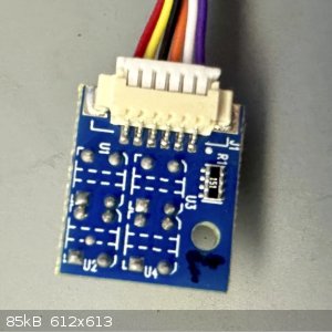
Valves
I mapped out the valve selection steppers and optocoupler traces. I have the valve selection steppers working fine now, although they overheat after
awhile, need to track that down.
A bit stuck on the optocouplers, I was expecting pretty clean signals but getting a lot of flickering, just touching the cable will set it off. A few
things I tried so far:
- Several hysteresis methods
- Shielding the cable and grounding it
- Activating the internal pull-up resistors on the ATmega (this stops the flickering, but also eliminates any input)
Maybe it needs a support circuit? Capacitor across the power lines? There are no markings on the couplers so I have no way to track down the
information sheet.
Synthesis
Also working on a first synthesis to try that doesn't need much more than heating and mixing.
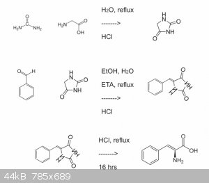
Current target looks something like this:
- Urea + Glycine -> Hydantoin
- Hydantoin + Benzaldehyde -> (?)Benzalhydantoin
- Hydrolysis of Benzalhydantoin -> (?)Phenylalanine
I think the product is Phenylalanine, but with a double bond to the phenyl group, not sure what the name of that is.
All the steps are simple, the products are easy to isolate, and with a little manual filtering (ie: cheating) I think it should work with the
components at hand - and I already have the chemicals, so that's a plus!
move.w %0x2700,sr
movem.l d0-d7/a0-a6,-(a7)
lea science,a0
jsr madness
|
|
|
Rainwater
National Hazard
Posts: 800
Registered: 22-12-2021
Member Is Offline
Mood: indisposition to activity
|
|
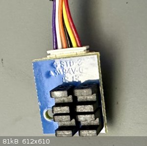
Std-3 = flame spread/smoke rating.
94-0v voltage rating of the pcb material.
Cant make out the other numbers
The part number should be of the U1-U4 devices.
Sometimes they turn the part number in so it cant be seen just to be mean, or simplify pcb layout
edit:
Any clue where got it from, listing or title?
[Edited on 9-11-2023 by Rainwater]
"You can't do that" - challenge accepted
|
|
|
mc68k
Harmless
Posts: 24
Registered: 26-10-2023
Location: Durham, NC, USA
Member Is Offline
|
|
The third line has the digits "1913", if that is helpful.
Yes - ModBus sounds like a good direction. I have a lab scale and calibrated thermometer that support RS-485 too, so that would ease integration of
all the parts.
Optocouplers
Scrounged around on Mouser and found two photo-interrupters that match the package dimensions and are visually similar to the components:
Omron EE-SX1103
ROHM RPI-243
Both of them show a schematic which suggests a pull-DOWN resistor on the output, which would answer the question of why the pull-UP resistor isn't
working.
I also mapped out the PCB and the SMD resistor marked 151 is inline with the transmitter's cathode, so it's just a current-limiter for the always-on
transmission LED.
That should solve the input problem! I'll try it later today.
Software
The Cronin lab released some of their software too. The Arduino command libraries look pretty good, so I'll probably give those a try instead of
writing them anew.
Cronin Lab GitHub
[Edited on 9-11-2023 by mc68k]
move.w %0x2700,sr
movem.l d0-d7/a0-a6,-(a7)
lea science,a0
jsr madness
|
|
|
Rainwater
National Hazard
Posts: 800
Registered: 22-12-2021
Member Is Offline
Mood: indisposition to activity
|
|
So I got a board in today,
ordered the nano, and they sent the micro. $4 vs $16
So win for me
It's an atmega32u4 instead of the atmega328p
Almost the same.
a little more ram
a few less gpio pins,
but the mcu core, clock speed, and peripheral interface is all the same
First test of the software,
still got some debugging to do and have to add a way to configure it.
Im thinging a 8pole dip switch
Test duration was 10 seconds per step
With the motor output fixed to 150ms duration "on" time each second
I compared the PCInt pulse rate to motor control timing errors and incorrect pulse counts
Pulse per second / timing error / missed counts
| Code: |
   0 / 0.04% / 0%
  1k / 0.19% / 0%
  2k / 0.60% / 0%
  5k / 1.73% / 0%
 10k / 83.1% / 0%
 25k / 400%  / 0%
 50k / $<"(ed/ 2%
|
So thats a good test.
I think between 2k would be the maxium feedback rate desirable.
Thats per second.
Without a lot of network traffic, under simulated conditions.
If the board was only controlling 1 device with feedback, we could get up to 1MHz
using a true Int pin and a 16bit hardware counter before we lose any precision.
Not revelent for a pump controller, but could be useful elsewhere
To control 4 feedback loops, i use the PCInt IRC routine which lags things alot.
I figure with the motors I got, the highest count rate will be about 6, maybe 8 per second.
Im hoping I can get together a BOM that doesnt require hand soldering or custom
boards. Just some jumpers to pins and she'll by hot to trot
Edit: that test used a function generator to make nice clean pulses
[Edited on 10-11-2023 by Rainwater]
"You can't do that" - challenge accepted
|
|
|
mc68k
Harmless
Posts: 24
Registered: 26-10-2023
Location: Durham, NC, USA
Member Is Offline
|
|
Hi Rainwater!
You lost me on this last post, let me see if I understand..
You got an Arduino equivalent board and wrote some software the controls a motor.
I don't understand this part, it sounds like you are pulsing power to the motor for 0.15 seconds, then off for 0.85 seconds?
What kind of motor are you using, and what is the motor driver?
| Quote: Originally posted by Rainwater |
I compared the PCInt pulse rate to motor control timing errors and incorrect pulse counts
Pulse per second / timing error / missed counts
|
Sounds like you are reading some data feed from the motor (hall sensor or photo-interrupter?), and triggering an interrupt on the ATmega. Then as you
speed up the motor, the Arduino doesn't see some of those pulses because it can't process the interrupts that fast.
What is generating the data feed from the motor, and how many pulses per revolution are generated?
| Quote: Originally posted by Rainwater |
If the board was only controlling 1 device with feedback, we could get up to 1MHz
using a true Int pin and a 16bit hardware counter before we lose any precision.
|
Agreed, attaching a hardware interrupt to a counter would reduce the need for system-level interrupts to read each pulse.
Does the ATmega support interrupt driven hardware counters?
I guess I should actually read the data sheet about the CPU I'm using!
| Quote: Originally posted by Rainwater |
Im hoping I can get together a BOM that doesnt require hand soldering or custom boards. Just some jumpers to pins and she'll by hot to trot
|
Nice! That's quick work for sure.
Ah, ok now I think I'm tracking. So the feedback was not from a motor at all, but an external pulse generator?
Lack of Progress:
I tried a variety of resistors for the pull-down (47, 330, 1k, 10k, 1M, 7M). All of them pulled the outputs to zero, but showed no change when
interrupting the beams.
I also pulled one of the other valve's optocoupler board, just in case I had fried the first one with my fidgeting. No difference.
So I'm back to stuck on that front.
One positive note is that the second board I pulled definitively IDs the photocopiers as ROHS brand.
move.w %0x2700,sr
movem.l d0-d7/a0-a6,-(a7)
lea science,a0
jsr madness
|
|
|
Rainwater
National Hazard
Posts: 800
Registered: 22-12-2021
Member Is Offline
Mood: indisposition to activity
|
|
If my stuff would get delivered I'd be able to finish this in a few hours but my area
is getting hit hard with USPS stealing anything of value. We made the news more than ones this year about it.
Using the Arduino library, its should be fully Modbus V1.1 complaint.
that means it will fit right in at any of the millions of industrial sites that use this protocol.
Here is some code not ready for hardware testing yet.
There is a paper I wrote in there when I was talking to myself trying to figure out
the how to, and why this stuff.
I used it as a map to write the .ino so if you get lost in one, refer to the other.
It may cause permanent hair loss, best to read it blindfolded.
| Quote: |
I don't understand this part, it sounds like you are pulsing power to the motor for 0.15 seconds, then off for 0.85 seconds?
|
I had the "motor" output pin, connected to an oscilloscope, No motor yet.
And one of the feedback pins, connected to a PWM signal 50% duty cycle function generator.
Just to speed test how fast I could drive the ISR before it started causing lag in the
motor control code. Also while in the ISR, all other code is paused.
Including the code that keeps track of time. any time in the ISR stops the clock and adds error.
Its the only way to make this work within the $20 price range I set for myself.
With a custom board, Each pump unit would have its own MCU and hardware counters all the way.
We'd be in the MHz range before any lag showed up.
I would like this to be something everyone could afford so im cutting corners here and there.
| Quote: |
Then as you speed up the motor, the Arduino doesn't see some of those pulses because it can't process the interrupts that fast.
|
correct. The Arduino has to get in and out of the ISR as fast as possible.
if another pulse comes in while still in the ISR, it will be missed.
| Quote: |
Does the ATmega support interrupt driven hardware counters?
|
depends on the flavor of chip you have. The uno, nano, and micro all have
2-5INT pins, and I think, 3 counters(16bit, 8bit, 16bit). Each counter can be set to a
different clock source. but their used for other things, like PWM output, millis() timing etc.
| Quote: |
I guess I should actually read the data sheet about the CPU I'm using!
|
took 4 years of collage before I could do that. youtube is cheaper.
I been building PLCs and custom hardware for factorys since about '98.
Edit:
those do not look like optical sensors to me, try a magnet or piece of iron.
Edit: normally i would use a TI SN74HC590 clocked by a CD74AC14E to obtain this type of feedback without losing pulses, but that requires custom
boards
[Edited on 11-11-2023 by Rainwater]
"You can't do that" - challenge accepted
|
|
|
Rainwater
National Hazard
Posts: 800
Registered: 22-12-2021
Member Is Offline
Mood: indisposition to activity
|
|
Here is some code ready for hardware testing.
Fixed the feedback not working at each boot,
Previous speed test is invalid do to a miss configuration.
have not ran it again.
Wrote the pin out for Arduino Micro and Arduino Uno R3.
Busted my budget, 1 full working pump will be about $45. with a 2 amp driver.
gave up on alibaba express
Edit:
Only got 2 more features to add before I slap a GNU GPL v3 and toss it onto gethub
Price for 1 setup without pumps and motor driver will be about $40.
Half being the micro board or Uno
I will update the ino to work of more than the arduino micro, and Uno soon
Still looking for a cheap replacement.
parts list can be found on amazon
Unfortunately with amazon, quantitys are off, you cant by just the number of items needed.
I suggest shopping around to save $$$.
After I wrap the controller for the peristaltic pumps
lets talk more about the chemputer language and additional equipment you need to run
[Edited on 13-11-2023 by Rainwater]
"You can't do that" - challenge accepted
|
|
|
mc68k
Harmless
Posts: 24
Registered: 26-10-2023
Location: Durham, NC, USA
Member Is Offline
|
|
Rainwater,
Great docs, thanks!
I'll add your BoM to my components list.
The ModBus terminology reminds me of CNC machines. The controller (GUI, command parser, etc) is separated from the driver (motion control, e-stop,
etc) and they use similar register blocks, each having a set of inputs and a set of outputs that get written to by address. In the case of gcode, all
of the registers are full sized integers though.
"Coils" reminds me of an industrial lathe from the 70s I worked on that used relay coils for all of its PLC programming, you could hear the relays
clicking as it computed the next machine state.
Pump Program:
Code looks good, no issues reading or understanding it. There are a few parts that dive below the Arduino wrappers, I'll just assume you know what
you're doing there. ;-)
I did notice the function RunPump() is given an unsigned value labeled "on", but later that unsigned value is compared against a negative number. I'm
guessing you want a signed value there instead? (line 215 in my copy)
Also, is ISR() valid for Arduino? Only docs I found are for attachInterrupt(), but I see people discussing the use of ISR(), such as this thread on arduino.cc
Progress:
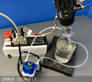
Not much to report, I gave up on the opto-sensors for the moment, I can still control the valve by counting steps.
I setup a valve and pump to start testing the steps-per-revolution for the valve's stepper. The valve is suspended over a reservoir, the pump will
pull from the reservoir and push water into the center inlet of the valve, which then drips out of the currently selected outlet back into the
reservoir.
Working on the programming for this test now.
move.w %0x2700,sr
movem.l d0-d7/a0-a6,-(a7)
lea science,a0
jsr madness
|
|
|
Rainwater
National Hazard
Posts: 800
Registered: 22-12-2021
Member Is Offline
Mood: indisposition to activity
|
|
For the ATmega series of mcu,
the toolchain includes some predefined c headers, ISR() is a #define statement that makes it easy to
sets up a void*function() pointer and automatically stores it into the appropriate register for callback.
The PCICR = Pin Change Interrupt Control Register
When enabled and triggered. calls the ISR function.
Arduino didn't make this a standard option within their API because not every mcu can do this.
This allows me to catch the feedback state of multiple pins at once.
Without this, i would only have 2 pins to use for receiving feedback
Thanks for pointing that unsigned out, i noticed on the scope that the reverse had quit working, but have not looked into it yet.
Would have had to find that the hard way when my parts show up.
I prototyped this around a dc motor, just to get the basics done.
Currently adding support for servos and steppers.
Will be doing a lot of housekeeping aswell, spliting different sections into different files,
just to clean up the mess and make porting easier.
Personal I hate having 1 box for this gadget and one for that gadget.
Im trying to make this thing run as many different motor types as I can squeeze
into the 2k of ram available
Im hoping i can get a max of 4k steps per second running a stepper.
And im already dreaming about how I can use a pump to pressurize the receiving flask in my reflux still to control takeoff ratios.
"You can't do that" - challenge accepted
|
|
|
Rainwater
National Hazard
Posts: 800
Registered: 22-12-2021
Member Is Offline
Mood: indisposition to activity
|
|
So just got home from work and some parts came in,
nano board, and max485,
still missing h-bridge, ir sensor, stepper motor
found all sorts of simple mistakes i made, got those fixed.
Found a heap stack collision hiding within the code. Fixed that
Switched to a less functional, less ram hungry, ultra fast modbus libary.
Still very compatible and functional but no longer iso standard.
Added servo and stepper motor support.
Servos work and tested over modbus,
still a few glitches needing a workout with stray pulses lasting too long.
(Likly the feedback isr blocking the stepper isr)
I haven't got the LN289 driver or stepper motor yet.
So no new observations there
but hoooked it up to the scope and got about 3-7k steps per second,
way too fast.
Have to hack the arduino stepper library and make it non blocking so speed control wont be an issue
Back to chemistry.
edit:
Link updated
still no stepper motor but with all the debug removed from the motor driver
its now capable of 28-32k steps per second on the scope
with speed control incorporated to slow it down to something reasonable
motors should be delivered this weekend, if not i can rip some out of other completed projects.
few more improvements needed.
-large amounts (>65k units) needs addressing
small amounts (<1 units) needs addressing
feedback, timer error re calculated (properly this time)
Servo position was effected with feedback above 1.8k
stepper speed begin reducing around the same feedback rate.
noted that feedback pulses occurring within a sweet spot of 5us~20us apart are
missed regardless of pulses per second. this is the ISR locked-out period.
feedback pulses have to be 20us or longer to trigger properly.
| Code: | pps / time error / count error
0 / 0.001% / 0%
500 / 0.3% / 0%
1k / 0.6% / 0%
5k / 4.1% / 0%
10k / 600% / ~0.1%
|
Edit:
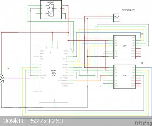
wiring diagram
[Edited on 18-11-2023 by Rainwater]
"You can't do that" - challenge accepted
|
|
|
| Pages:
1
2 |
|


