Nestea
Harmless

Posts: 15
Registered: 13-11-2018
Member Is Offline
|
|
cell design electrode surface, correct calculation
Hello friends,
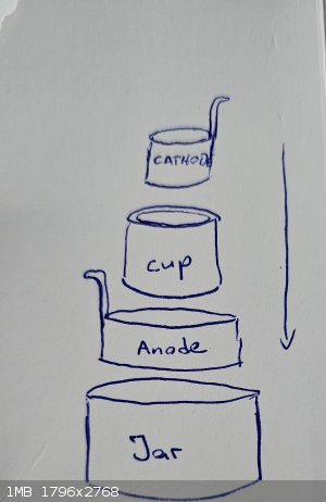
i am building a divided electrolysis cell, with a ceramic pot as divider, placed in a glass jar.
check the attached sketch.
Jar is anolyte compartment.
Inside the jar a cylindrical sheet metal anode
Inside of this the ceramic pot
Inside of the ceramic pot a cylindrical sheet metal cathode
The pot holds ca. 100ml catolyte solution.
i checked the dimensions of the sheet metal needed to form a cylinder thats fits in the pot.
The dimension for the cathode is: 17cm length and the height is 4,7cm
For the anode: 24,5 lenth and 4,7cm height
I want to run this at 0,1 A/cm² cathode surface.
that would be 17 x 4,7 = 79,9 cm²
79,9 cm² x 0,1 A = 7,99 A
but if i count the inside as well it would be 159,8 cm²
159,8cm² x 0,1 A = 15,98 A
16 Amps in such a tiny cell would boil that thing in no time.
Sure i can make the electrode surface smaller.
But my main question is, when it comes to calculation:
should i count both sides of the cathode surface, (inside and outside of the cylinder) or just the outside (the side facing to the anode)
What is right?
|
|
|
Sulaiman
International Hazard
Posts: 3558
Registered: 8-2-2015
Location: 3rd rock from the sun
Member Is Offline
|
|
Use just the surface area of one side for calculations,
Negligible current will flow via the other side.
Be sure to allow plenty of time for the electrolyte(s) to soak through the pot.
How long?.... Depends upon the pot.
CAUTION : Hobby Chemist, not Professional or even Amateur
|
|
|
Nestea
Harmless
Posts: 15
Registered: 13-11-2018
Member Is Offline
|
|
That makes sense. But when i shrink the height of the cathode, for less surface are to run on lower Amps, the electrons can flow over the top of the
cathode i guess.
In this case i should count both sides?
Yes, you are absolutley correct. I did a few tests in the past. soaking the pot overnight in sulfuric acid reduces the resistance extremly.
Or just run the cell 3 times or so. On the first run, resistance is high and gets lower with every run.
|
|
|
Sulaiman
International Hazard
Posts: 3558
Registered: 8-2-2015
Location: 3rd rock from the sun
Member Is Offline
|
|
Within the volume enclosed by the cathode there will be negligible electric field to move ions.
If you use a shorter cathode, use less electrolyte 
P. S. If you keep the very top of your electrodes above the electrolyte,
the tabs will last much longer.
[Edited on 28-11-2023 by Sulaiman]
CAUTION : Hobby Chemist, not Professional or even Amateur
|
|
|
Nestea
Harmless
Posts: 15
Registered: 13-11-2018
Member Is Offline
|
|
Ok, so in this case perforationg the cathode, or cutting slots in it won't work either? 
I summarize: Just counting the surface directed to the anode in this kind of setup right?
I used lead electrodes before. never had any issues with corrosion. Maybe i will make 2 or 3 tabs on the electrodes and attach to a lid.
When my cell is ready i can show the results here. And than i will try the reduction of Nitrobenzene to Aniline first. But It can be used for all
sorts of electrochemical synthesis.
Next step is to build in a reference electrode for running the reduction on a fix overpotential. This is something i have no idea at all. Hope you
guys can help me then.
|
|
|
Sulaiman
International Hazard
Posts: 3558
Registered: 8-2-2015
Location: 3rd rock from the sun
Member Is Offline
|
|
Just guessing now as not tried....
I imagine that some ions would be attracted from the inside,
very near to any slots or holes.
The larger the hole size the farther the electric field gradient will spread on the inside.
An extreme case would be a very 'open' wire mesh where the active area would be near to the total exposed area of wire...I guess.
CAUTION : Hobby Chemist, not Professional or even Amateur
|
|
|
Nestea
Harmless
Posts: 15
Registered: 13-11-2018
Member Is Offline
|
|
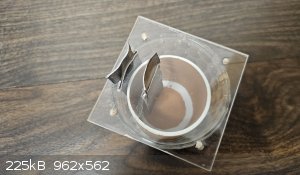
Okay, i want to show you guys me cell design. Nothing special, but it is practical and it fitts my needs for experimenting.
The outer anolyte chamber is a glass from a candle.
the dimensions are: height: 8,8cm, diameter: 8,3
The clay pot is a flower pot i sanded the outer painting of. painted pots can be sanded, but glazed pots not really.
the dimensions are: height: 6,7cm , diameter: 6,4 cm
i made a lid and electrode holder from 5mm acrylic, cut to 9,2cm x 9,2cm. i drilled holes in the corner and glued toothpics in, so i can place the lid
exactly on the same spot every time and keeping it in place.
i also made 2 slots for the lead electrodes in the distance of 2 cm.
electrodes are roofing lead sheets of 99,94% lead. dimensions are: length: 9,5 cm in total, and width: 3,1cm
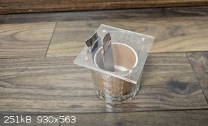
i can fill up the pot with ca. 130ml catholyte and leave 1,5 cm of breathing room on top.
the outer glass anolyte chamber is on the same level of liquid at 60ml anolyte.
the part of the cathode, that is immersed in the catolyte is 4,5 cm x 3,1 cm = 13,5 cm² surface are, that is facing to the anode.
With a current density of 0,1 A/cm² i can run this cell at 1,35 A
cathode can be replaced by a cylindrical shape of larger surface area if needed.
the whole cell can be placed in a cooling bad, for temperature control. a hole in the middle of the acrylic sheet can be drilled, for inserting a
thermometer.
aah and for stirring i will use just a regular stirring rod for magnetic stirring the catholyte.
what do you guys think?
|
|
|
semiconductive
Hazard to Others
Posts: 287
Registered: 12-2-2017
Location: Scappoose Oregon, USA.
Member Is Offline
Mood: Explorative
|
|
Looks decent. Sanding pots is a bit of work.
I did a search for "porous cup", and found several suppliers for battery demonstrations.
I paid U.S. $10 for one. ( Around 8 pounds, British. )
|
|
|
Nestea
Harmless
Posts: 15
Registered: 13-11-2018
Member Is Offline
|
|
Yes, it was a bit of work. soaking over night in conc. NaOH helped a bit. DCM should work better, if it is just paint.
I know the porous cups. you mean the white ones. never tried.
they are long but narrow, dont like that shape for a cell, but they are thin and should have pretty low resitance.
maybe i will come up with a variation with car battery seperator. i have a dead battery laying around. they should be heat weldable, because they are
of PE.
In this case i would make a small pouch, and use it as the anode chamber and the rest of the glass as cathode chamber.
Ok, now.. i am happy with my design for now, but i want to try a controlled potential electrolysis. My knowledge in this topic is very limited. so i
need some help of you guys.
I know, i need a reference electrode.
I would choose Ag/AgCl instead of Calomel, just because i want to avoid mercury, or mercury contamination of my solution ( dont know if this is even
possible).
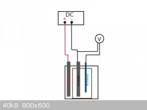
A potentiostat is way over my budget, and i am not the best at electronics. So i would regulate the potential manually.
For nitrobenzene reduction the potential should be -1,1V as far as i know.
Would it work, if i connect the reference electrode to a multimeter, together with the cathode like in my drawing? Is the voltage shown by the
multimeter the actual potential?
And how can i adjust it? by simply adjusting the flowing current at my DC power supply?
i would be very grateful for help.
[Edited on 2-12-2023 by Nestea]
|
|
|
semiconductive
Hazard to Others
Posts: 287
Registered: 12-2-2017
Location: Scappoose Oregon, USA.
Member Is Offline
Mood: Explorative
|
|
I am not a chemist, and don't know much about nitrobenzene. I can't guide you there.
Having carbon and nitrogen in that configuration, it seems like it might be able to form cyanide.
I wouldn't try this synthesis, myself; too risky. Mercury is the least of your problems.
Just for general information; with no warranty or suitability promises:
The basic idea you have about using a volt-meter, is correct.
But: There are high impedance volt-meters, and low impedance meters on the market;
Low impedance (cheap volt-meters especially with needle, not digital display), will put enough load on the reference electrode to mess up the reading.
|
|
|
Nestea
Harmless
Posts: 15
Registered: 13-11-2018
Member Is Offline
|
|
Nitro reductions are relativly common i think.
I did a bit of research about the electrolytic reduction of nitrobenzene, and the possible products should be aniline, phenylhydroxylamine,
nitrosobenzene and p-aminophenole.
Never read about cyanide formation.
Yes, i heard about that phenomen with the impendance. regular digital multimeters have an 10 MΩ input inpendance. There are special tools with higher
values in the GigaΩ ranges, but 10 MΩ sounds not so low i think. It doesnt have to be super precise.
Does it matter, if the reference electrode is placed behind the working electrode, or should it be in the middle, between the cathode and anode?
what is exactly effecting the potential, the current that is flowing? So, can i regulate the potential, by regulating the current?
|
|
|
semiconductive
Hazard to Others
Posts: 287
Registered: 12-2-2017
Location: Scappoose Oregon, USA.
Member Is Offline
Mood: Explorative
|
|
Yes, it's the current that flows due to the meter impedance that is the problem.
Regular multimeters can have any resistance, manufacturer dependent; and some even have switched capacitance .... if not listed in the manual, the
easiest way to check it to measure one meter against another in the 10M ohm+ setting.
Yes,
There can be a continual voltage drop between the counter electrode and the working electrode. I haven't noticed it being a problem in the (very few)
cells I work with as long as the reference electrode is closer to the working electrode than to the counter electrode. I imagine placing the
reference electrode outside the path between the two electrodes is safest.
But I also don't have a lot of experience; just in the 10's of experiments with a platinum/frosted glass hydrogen reference electrode. I've never
used the electrode you are trying.
|
|
|
Nestea
Harmless
Posts: 15
Registered: 13-11-2018
Member Is Offline
|
|
platinum/frosted glass hydrogen reference electrode? never heard of that.
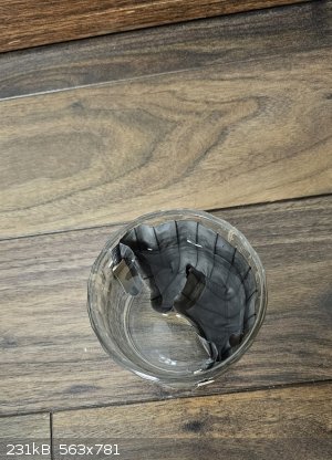
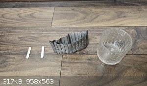
anyway, i finally cracked open a car battery and took the seperators out.
Sadly, they cant be melted or heat welded
i think because of the high silica content they have. so i had to use them as they are. Just shortet them at the top with a cutter. They are a bit
like paper.
I used some neodym magnets to hold the pouch at the inner wall of the glass. later i added a extra magnet in the middle. otherwise it was too wobbly.
In a real working setup, the magnets in the electrolyte should best be wrapped in teflon tape.
In this way i formed two compartments in the beaker. anode and cathode compartment.
i did a resistance comparison with the clay pot. With the seperator at 12V i had twice the current flowing as with the clay pot.
ok, i just let the pot soak up the electrolyte for a few minutes, maybe that effected the resistance too.
So.. the seperator works. Doesnt look very nice ok. But i think i would still prefer the clay pot. Its nicer to work with.
|
|
|
Sulaiman
International Hazard
Posts: 3558
Registered: 8-2-2015
Location: 3rd rock from the sun
Member Is Offline
|
|
Not that it matters much on a small scale but
for the electrolysis of water 1.48V is the theoretical minimum,
exotic/expensive catalysts allow down to about 1.5V per cell
A good target would be around 2V per cell.
12V means about 17% efficient only,
(plus some gain due to the heating caused by the over voltage)
CAUTION : Hobby Chemist, not Professional or even Amateur
|
|
|
Nestea
Harmless
Posts: 15
Registered: 13-11-2018
Member Is Offline
|
|
You are absolutely right. 12V was just for testing, because i had just a 12V car battery charger on hand yesterday.
i'm not so in to water electrolysis, but yes, 2V per cell would be ideal in that case. for organic electrochemical reactions it is depending on
electrolyte aswell and the resistance of course. At 2 V the current was very low in this setup.
Normally i would run this cell at 2-3 amps. The voltage was in most cases 5-8 volts in my experiments.
Maybe this battery seperator could help to lower the voltage and the heating of the cell.
|
|
|


