Farben-X
Harmless

Posts: 4
Registered: 25-3-2024
Member Is Offline
Mood: No Mood
|
|
Homemade Structural Analysis X-Ray Machine
Hi everyone, I recently finished my third prototype of a structural analysis x-ray machine. It took almost 1 year to reach this stage, mostly because
of electronics problems, but so far it seems to work, i didn't know if I should post this in electronics or analytical chemistry because both subjects
are relevant here, but because the end goal was to achieve diffraction image I thought of posting it here:
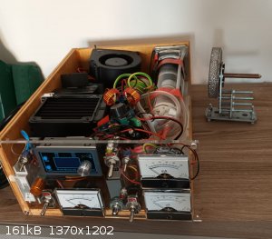
this is the current version, in the front panel the various meters are used to control and measure the HV voltage and current applied to the soviet
bsv-29 structural analysis xray tube.
The HV is generated by a system of flyback transformer and a 4 stage CW multiplier, the tube filament power supply is made of a ZVS-driven high
voltage insulated transformer that transmits the power through the HV insulation of the HV line, that is because the anode of the tube is at ground
voltage, and the filament instead is at -20-60KV, these type of x-ray tube work with negative HV potential.
All of this is configurated as follows:
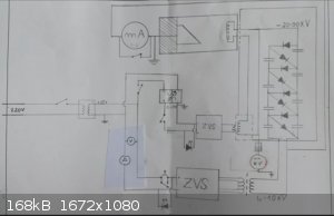
This is the electrical scheme.
Now on the more chemical side:
First of all, I wanted to achieve single crystal XRD, to prove the system was working and as a starting point for eventual upgrade to a goniometer
head.
To make the single crystal XRD I used the X-ray machine, a collimator system, a crystal obviously, and a recording system:
COLLIMATOR:
This was made using a long copper tube with two 3D printer extruders at the extremities as collimating pinholes, with diameters varying from 0,2-1mm,
the tube was surrounded by a 1cm lead block to prevent xrays from going in that direction and hitting the recording system:
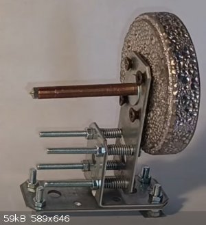
everything was then mounted on a metal structure that ensured the copper tube was parallel to the surface, to regulate this I used the 4 screws with
springs.
The collimator creates a beam of x-rays that is pretty collimated, this is due to the relatively high length of the tube itself, I tried with a
shorter collimator with little success.
THE CRYSTAL:
This is what we were here for, the most important aspect for XRD to work is that we have a single crystal that is as THIN as possible, this is because
in amateur apparatus the power is limited, normal 150k$ machine uses 2KW of power, my uses 200W at most, so to be able to observe diffraction in a
human lifetime it is really important to limit the X-ray absorption from the material as much as possible, and to do so we need a thin crystal, the
first 3 candidates for my experiments were material widely available and easily made in to thin slices, and they were:
Mica, NaCl, and Menthol so I also tried organic substances.
Another important factor for single crystal XRD is that the substance needs to be a single crystal in a physical-chemical way, so as little as
possible grain boundary to achieve better diffraction.
Mica was extracted from a microwave by slicing a thin piece of it from the gray part of the microwave that is in front of the waveguide.
NaCl crystal was made by finding a single crystal that can be easily grown or found in the kitchen salt with a little bit of patience, then I sliced
it along one of its flat sides to get a thin slice of NaCl, subsequently gluing this to a metal wire I proceeded to dip the crystal in water to
dissolve it just a little bit at a time, to get even thinner slices, I repeated the dipping method until I got the thinnest as possible slice left
without it disappearing.
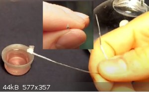
The same thing was done with menthol, but the solvent to thin it was alcohol because menthol is not soluble in water.
the crystal was then placed at the end of the collimator system, as close as possible to avoid the beam spreading.
RECORDING:
To record the diffracted xrays I used a dentist auto-developing film that is normally used to take xrays of teeth, the film was placed 1-1,5cm behind
the crystal to record the diffracted laue image, the distance parameter is still to be optimized because it is a tradeoff between the number of points
recorded and their spatial distance, closer film have more point but closely packed, so harder to distinguish, farther fil have less point but more
distanced.
The exposure time at first was really a guessing game, no one used a setup like mine before, so I didn't have a clue on how much time I needed to
expose the crystal and film.
EXPERIMENTAL PARAMETERS
In this project, this has been the hardest part, It took me several months and hundreds of failed radiographs to achieve a successful result. During
this time I changed and tried almost every possible combination of the following parameters:
exposure time
tube high potential
tube current
tube filament current
tube/machine power input
collimator beam diameter
collimator tube length
film-crystal distance
collimator-tube angle and distance
flyback operating frequency
and have had a successful result only recently with the following:
tube HV at around 34-40KV with as much tube current as possible, to maximize the power input, but maintaining the operating frequency<20kHz and
using the tube filament current to modulate the current flowing in the HV system to achieve the maximum being careful not to reducing the HV
potential.
This is a photo of my experimental setup:

where the upper meter is the current flowing in the anode, and the lower meter indicates the -HV potential
Now I will show the experimental result for the different substances I tried:
MICA HV 34KV exposure 1h50min
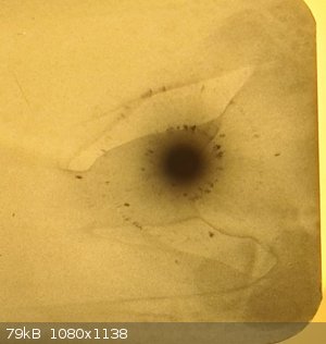
NaCl HV 30KV exposure 30min
the dot you see in the bottom right corner is not a diffraction spot but a feature present on all film from the manufacturer
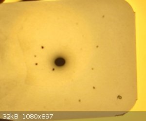
Menthol HV 38KV exposure 50min
the dot you see in the bottom right corner is not a diffraction spot but a feature present on all film from the manufacturer
So finally the experiment worked, the big dot you see in the center of the film is the transmitted X-ray beam that did not diffract, and all the dark
spots you see surrounding the big dot in the center are the diffracted beams, they are created by constructive and destructive interference of x-rays
with watch other.
The diffracted beam is the most important information one can have about his crystal, because from a single crystal diffraction pattern,
theoretically, one could work back to the exact position of the different atoms inside of the crystal lattice and determine exactly the crystalline
structure of the substance.
In 1912 Max Von Laue discovered this and won the Nobel Prize, at the time they did all of this on paper, I have no clue on how that is possible, but
they were able to determine the crystal structure of different minerals.
Now the hard part is how to interpret these data, unfortunately, I am not a crystallographer, but I know modern single crystal XRD machine uses a
digital sensor and fully automated system that can determine the structure from the diffraction pattern using smart software. Does anyone have any
idea how it would be possible to use these recorded films and modern software to work back the crystal structure? this would be the last step in
achieving a complete system that would be able to give the amateur a way to determine the structure of crystalline compounds without the need for
million-dollar research equipment.
Another possibility for further experimentation is to develop a powder XRD that would need a goniometer head and a more complicated detection system,
but that is too far for now.
If anyone has any questions regarding the more technical side that I didn't fully cover please ask, I would be happy to answer.
Also if anyone has any clue on any software that could be used to determine the structure starting from those patterns, that would be wonderful.
Many thanks
PS This is my first post, so sorry in advance if I messed up anything or did something wrong.
[Edited on 26-3-2024 by Farben-X]

|
|
|
Sulaiman
International Hazard
Posts: 3947
Registered: 8-2-2015
Member Is Offline
|
|
Wow!.. What an amazing first post
Welcome.
Nice work there.
I'm impressed and keen to see your progress.
CAUTION : Hobby Chemist, not Professional or even Amateur
|
|
|
j_sum1
Administrator
Posts: 6475
Registered: 4-10-2014
Location: Limbo
Member Is Offline
Mood: Just got through yet another "take this job and shove it" moment.
|
|
That is pretty darned impressive.
One of my papers at university included a decent segment on xray crystallography. At the time, I would say that I understood it really well, but a
couple of decades on non-use and I am rusty on the details.
I do remember a comparison of single crystal methods with powder methods. Single crystal only works for thin crystals because of "a relaxed third
Laue condition". (I forget the exact wording of the three Laue conditions). The gist of it is, with a thin section, the constructive and destructive
interference is less pronounced which means that the x rays intensify on a short line instead of a single dot in 3d space. This means that there is a
better chance of the interference pattern intersecting the plane of the x ray film.
We did a cool lab using aluminium powder. Because the wavelength of the xrays was known, we were able to calculate the interatomic distance of the Al
atoms. It was one of the highlights of my time at university. With nothing more complex than some graph paper, a ruler, and some developed film, we
were able to determine that distance to better than four significant figure accuracy.
I would have to derive it from first principles again, but I recall working out the geometry of the diffraction pattern by means of a transformation
into 3d reciprocal space -- that is, negative three dimensions. With this transformation, parallel planes in a crystal mapped onto a grid of single
points. From there is was simple trigonometry to calculate any desired unknowns in the system. It was all pretty cool.
Anyway, let me repeat that this is very impressive work in an amateur setting. Thanks for sharing. And welcome to the board.
|
|
|
Farben-X
Harmless
Posts: 4
Registered: 25-3-2024
Member Is Offline
Mood: No Mood
|
|
hi guys, thank both of you very much for your kind words, I'm happy you liked the project.
I am currently researching the topic, reading articles and information about available programs for structure determination, but I think it has become
a very sectoralised topic, that only people working in the field know, but even then the software is made to work with particular data format.
In the meantime I made a video about the building of the machine with some recordings, if you want to check it, here it is:
https://youtu.be/EKCt-dHuzS4?si=j3FWV2Kah3MYoeB2
In the meantime the search continues.
|
|
|
Farben-X
Harmless
Posts: 4
Registered: 25-3-2024
Member Is Offline
Mood: No Mood
|
|
Hello, it has been quite a long time since the last post, but I'm now reporting a follow-up regarding the successful use of this technique to get real
crystallographic data and consequently the cell parameters of sodium chloride. The technique I employed this time (powder XRD) differs from the one
described in the last post (single crystal XRD) mainly due to the easier data interpretation required.
So this time a sort of Debye-Sherrer camera was used, consisting of the x-ray collimator, containing a very small amount of very finely pulverized
NaCl placed at the end of it. This way the X-rays struck the powder and got diffracted in every possible orientation that satisfies the Laue condition
(the microcrystalline powder contains all possible orientations so a circular diffraction pattern is formed instead of a single dot).

There are a lot of crystallographic plane that can lead to diffraction, but for NaCl the more intense one is originating from the 200 plane
orientation, as it contains both Na and Cl atoms, creating a much stronger interaction probability between the atoms electronic density and the x-ray
photons, (in fact this reflection will be the only one visible as the other ones are too dim and got lost in the noise).
The diffraction image has been taken by a Co anode BSV tube at 20kV, to have the emission of around 6keV from Co without too much brehmstrahlung and
took around 20min.
The photographic plate is a normal xray film in front of an Eu based medical intensifying screen, kept light sealed by wrapping the two in kitchen
aluminum foil, (the film needs to be developed like normal photographic film with developer and fixer).
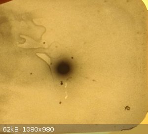
This here is the photographic plate recorded:

A very faint and thin line is visible around the central transmitted dot.
The reason for the central transmitted dot for being so big, even though the xray beam is less than 1mm in diameter, is probably due to a combination
of air scattering, and film transmitting part of the light inside of itself enlarging the image during very long exposures.
Regarding data analysis, it is relatively simple by employing Laue condition: λ=2*d*sen(Θ) we know Θ from 2Θ shown in purple in figure, we know
lambda that is the Co emission line (weighted average between Ka and Kb as we don't employ any filter to remove the Kb), can get the d spacing between
the 200 planes, and then use the relation between d and a (the cell parameter for NaCl) to get the cube side dimention.

It is also possible to get a very rudimental error range, based on the thickness of the diffraction track on the image, that gives an uncertainty on
the angle 2Θ, so by propagating this error we get the final result for the cubic cell parameter of 5,6±0,4 Å, that is surprisingly good value,
close to the real one of 5,64Å.
The main problems in this experiment are the transmitted beam that cover up the less intense diffraction ring, which if present and averaged out with
the other could yield a more precise value, this problem could be solved by using a beam stop right after the sample, also the very low energy of the
diffracted rays (6keV) pose a real problem with detection, that is currently not very efficient, as the xrays get absorbed by the sample, by the
aluminum foil surrounding the photographic plate, by the film itself before they reach the scintillator, the only way to solve this problem it so
change the tube with a heavier target like Mo, or Cu, but this is limited by the avalability of these rare tubes.
In conclusion we got a really promising result of 5,6±0,4 Å for this method, compared to the real one of 5,64, and there are still a lot of possible
ways to improve the speed and result precision.
[Edited on 29-6-2025 by Farben-X]
|
|
|
Sulaiman
International Hazard
Posts: 3947
Registered: 8-2-2015
Member Is Offline
|
|
Wow! Great work
only just noticed this topic but goodness me,
what an excellent bit of work, super impressive.
Some years ago I had a quick look at crystallography
and quickly realised that the mathematics would melt my brain 
Supercalifragilisticexpialidocious2
CAUTION : Hobby Chemist, not Professional or even Amateur
|
|
|
|


