DIY temperature controller for IKAMAG-RET
Many years ago NurdRage made a video about making a DIY PT1000-based thermocouple for his hotplate.[1] The hotplate in question was a
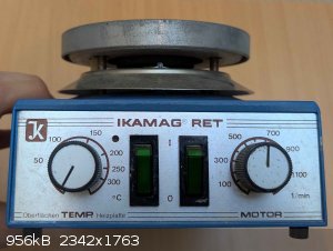
rather modern one, which displays the temperature on the hotplate display. This is not about those types of hotplates. This is about the old
IKAMAG-RET style hotplates for which the temperature control circuit is external to the hotplate and which would work with entirely analog circuitry.
And while this is a very simple and quite cheap project, I found a complete lack of information regarding this online, so I hope it is helpful for
some.
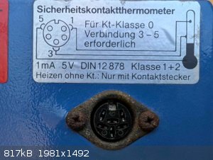
Pinout on IKAMAG-RET:
The plug is a 6-pin DIN connector, of which three are needed: Pins 1, 3 and 5. To understand what the pins are doing, it is helpful to look at the
function of the mercury thermometers.[2]
In the mercury thermometers used for these plates, three connections are important. Pin 5 is connected to the bulb of the mercury. Pin 3 can be
connected in various ways, for example to a conductive layer on the outside of the capillary, making contact with pin 5 at the bulb. Finally, pin 1 is
connected to a wire suspended above the mercury inside the capillary.
Connection 3-5 serves to check if the thermometer is broken. If the thermometer breaks, the capillary breaks and opens the circuit. This tells the
hotplate to stop heating.
Connection 1-5 serves to check the current temperature. If there is no connection, that means the mercury is below the wire, and the plate needs to
heat. When the mercury touches the wire, the circuit closes, which signals to the hotplate the target temperature has been reached and to stop
heating.
The resistance between pin 3 and 5 must be less than 1 kOhm based on the corresponding norm. For the model of hotplate I am using, there is 8 V on the
pins, and connection 1-5 says 1 mA (max?). In my experience, a 20 kOhm resistor works well (so around 0.4 mA).
Thus, we can turn the heating on and off by placing a switch and a 20 kOhm resistor between pin 1 and 5, while pin 3 and 5 are shorted.
PID-controller:
I went with a cheap REX-C100-type controller off ebay.[3] There are several types, and here it is particularly useful to pick a model that
controls an internal relay and not an external relay. My model is a REX-C100FK02*M-DN, the M signifies that this has an internal relay. (Check the
datasheet in [3].)
The connection for hotplate pins 1-5 (and the resistor) are placed across the normally closed part of the output relay: When the PID signals to heat,
it will open, thus telling the hotplate to keep heating. The rest of the connections are for the power for the PID as well as the thermocouple, in my
case a type K (again, this is dictated by the type of PID used).
And that's it! All in all, the PID-controller cost me about 16 euros, the cables, DIN connectors, thermocouple and resistor cost me about the same, so
in total you can make one for around 30 euros. Less if you already have old cables and connectors laying around you can repurpose for this project.
More if you don't already have a soldering iron.
As an alternative, you could also use an Arduino nano with an PID library. This means more effort in assembling and coding, and you also need to buy
things like a display, a rotary encoder and a thermocouple adapter board, but you could make it just like you want it to. You could even make your
hotplate do arbitrary temperature ramps.
I should also say that as of right now I haven't tested the setup with regards to how stable it can hold or how fast it can reach a set temperature,
but I have verified that the PID-controllers output is correctly interpreted by the hotplate.
Images:
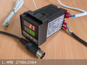
Final wired PID-controller
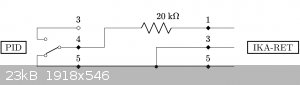
Circuit diagram
Sources:
[1] - NurdRage, "Make a thermometer probe for a westlab/scilogex hotplate", YouTube 2015, https://www.youtube.com/watch?v=ORBgemwMLS4
[2] - DIN 12878, 1980, "Elektrische Laborgeräte, Einstellbare Flüssigkeits-Glas-Kontaktthermometer und Steuergeräte"
[3] - REX-C100 datasheet: https://www.mpja.com/download/rex-c100.pdf
Attachment: rex-c100.pdf (362kB)
This file has been downloaded 308 times
Attachment: DIN_12878_1980_12.pdf (818kB)
This file has been downloaded 128 times
[Edited on 16-8-2025 by Diachrynic]
we apologize for the inconvenience
|


