woelen
Super Administrator

Posts: 7977
Registered: 20-8-2005
Location: Netherlands
Member Is Offline
Mood: interested
|
|
Balun for antenna for FM transmitter?
I obtained a small FM-transmitter which emits appr. 1 Watt of power and I made a dipole antenna for this transmitter, which is connected through a
coaxial cable of appr. 5 meter length.
I have done some searching on internet and many people say that a balun is needed at the point where the coax cable is connected to the antenna.
I only have very superfluous knowledge of RF-transmission. Can someone explain what this balun is for? I followed the directions on some dutch forum
about electronics where they told me to make 4 or 5 windings of coax cable around appr. 3 inches diameter of air, just before the point where the coax
cable is connected to the dipole. I have the earthed part of the dipole pointing downwards and the part which is connected to the core of the cable is
pointed upwards (also according to directions on the dutch forum). The center of the dipole is appr. 1.5 meters above the ground and both sticks of
the dipole I gave a length of 0.95*c/4f, where c is the speed of light and f is the frequency. For a 100 MHz frequency this is 71.25 cm.
Is there a way to measure how well this antenna performs? Does it emit nearly all of the provided power, or am I just reflecting back power into the
end-stage of my transmitter?
Another issue I read about is about impedance matching of the antenna. I have a transmitter with a 50 Ohm SMA output. Dipoles are said to be 75 Ohm
and this apparently leads to sub-optimal behavior of the antenna. Can someone explain this to me?
For now, I have the stuff connected, I put a 14 dB terminator at the end stage and have the antenna connected to that. The transmitter works great but
before I allow full power to be transmitted I first want to be sure that the antenna system is OK. For now the terminator dissipates nearly all power
and the transmitter sees an impedance of around 50 Ohm, so the thing is safe now.
|
|
|
phlogiston
International Hazard
Posts: 1376
Registered: 26-4-2008
Location: Neon Thorium Erbium Lanthanum Neodymium Sulphur
Member Is Offline
Mood: pyrophoric
|
|
balun comes from 'BALanced UNbalanced' and they are used to match an unbalanced source (such as most transmitters) to a balanced load (such as a
dipole antenna) or vice versa.
Picture the unbalanced signal as follows: one of the two 'wires' coming from your transmitter is a fixed voltage, usually ground, and connected to the
outer mantle of a coax cable. The other 'wire' is connected to the inner conductor and varies with time as RF signals do.
In contrast, the two wires carrying a balanced signal each carry the variable voltage, in antiphase. You want to induce a standing wave in both of the
two radiators of your dipole. If you were to simply connect the unbalanced signal, one wire to each radiator, one radiator would remain 'fixed' with
respect to ground. The Balun solves this. It is essentially a little transformer and the two wires coming out each carry the RF signal in antiphase.
You might ask why not provide a balanced signal at the transmitter end to start with? The answer is that if you were to transmit a balanced signal
into a coax cable, it will cause the cable to radiate as if it was an antenna, since the outer conductor then carries RF signal.
Antenna performance is most commonly measured with an instrument called a SWR meter ('Standing Wave Ratio'). Essentially, they measure the ratio of
the power going to the antenna, divided by the power reflected back. You could make one yourself, there are numerous designs availble online for
various frequencies.
In practical terms, if the impedance of a source and load are exactly matched, all of the power emitted by the source is absorbed by the load. If not,
part of the RF wave is instead reflected back towards the source, leading to a loss of power.
If your coax cable and antenna have a different impedance, you will see that the impedance 'seen' by the transmitter 'looking into' the cable becomes
a function of cable length. If the antenna and cable are matched, the impedance looking into the cable is constant (and may or may not be matched to
the transmitter, depending on its design).
You can also asses this problem using the VWR meter. If you find little or no power is reflected from the antenna, they are well matched.
You say that dipoles have 75 ohm impedance, but it really depends on whether you have a 1/2 wave , 1/4 wave, or another dipole.
At what approximate frequency are you transmitting?
I can recommend the www.circuitsonline.nl forum. Experienced people and friendly, helpful atmosphere.
[Edited on 1-11-2012 by phlogiston]
-----
"If a rocket goes up, who cares where it comes down, that's not my concern said Wernher von Braun" - Tom Lehrer |
|
|
woelen
Super Administrator
Posts: 7977
Registered: 20-8-2005
Location: Netherlands
Member Is Offline
Mood: interested
|
|
Thanks for the link. It looks interesting.
I am transmitting on the FM (on an empty spot somewhere between 88 MHz and 108 MHz). The spot must be empty both on air and on cable.
I intend to use the transmitter for transmitting music and computer-content from my house to nearby places. So, 1 Watt may be a little strong, but a 6
dB attenuator can be used to reduce range somewhat. But I do not want to blow out the end-stage of the transmitter, hence my questions about the
antenna. Even with only 1 Watt of power, it is easy to blow out a small power transistor.
I think that I indeed want such an "SWR" meter. Buying such a thing is too expensive for me, I need to find a circuit for such a device.
I assume that my dipole is a so-called 1/2 wave dipole? Its total length is half of a wave length (i.e. just below 1.5 meters for a 100 MHz signal).
|
|
|
m1tanker78
National Hazard
Posts: 685
Registered: 5-1-2011
Member Is Offline
Mood: No Mood
|
|
FM transmitters are a lot of fun - I've built several over the years. IIRC, I got up into the 12-15 watt range.
I'm not fluent with all the theories of RF but I view impedance as the equivalent of resistance in a DC circuit. The transmitter 'sees' a resistance
to the wave propagation. If the impedance at the output of your RF stage matches the impedance of the antenna, you minimize losses in a similar way to
using the same diameter water pipe throughout your house. Bad analogy but might help you visualize it a little better. Also, you might have 3/4" water
pipes in your house but your bathroom faucet probably has a smaller diameter feed.
The balun helps to decouple the coax cable from your antenna and probably to some degree from your resonant tank circuit. To help you understand this,
you might try connecting a single wire between the output stage of the transmitter and the antenna. Tune the circuit or receiver then bring your hand
near the wire. I'll bet the frequency drifts considerably. The point of the coaxial cable is to avoid these stray influences but you must decouple it
from the resonant circuit. By doing so, the stray signals are shunted to ground and stray capacitance has little or no effect on the tuned circuit or
wave propagation. It isn't quite as simple as earthing the outer conductor of your coax cable, I'm afraid. Do some research on resonant
cavities. That should help you better understand impedance and the effect it has on RF signals.
BTW, watch out for harmonics (multiples of your fundamental frequency) and spurious signals that may cause nearby interference.
Did you assemble the transmitter from a kit or from a schematic? If so, it might be helpful if you post the schematic.
Tank
Chemical CURIOSITY KILLED THE CATalyst.
|
|
|
IrC
International Hazard
Posts: 2710
Registered: 7-3-2005
Location: Eureka
Member Is Offline
Mood: Discovering
|
|
If you are trying to feed a dipole with a balun DO NOT ground the bottom of the antenna. Both quarter waves must float from earth. Would help if you
would post a pic of your antenna close up. You could just transmit on the top element as a simple quarter wave antenna, connecting shield to the
bottom or ground. I would have to see how your antenna is mounted and to what. The top 1/4 would connect to the coax hot, no balun. Not too far off 50
ohms. Also, are you trying for omni as the receiving locations are around, or could you build a yagi pointed at the single point of reception.
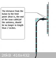
http://braincambre500.freeservers.com/Balun%20for%20dipole.h...
If you look at the pic I posted from the page link above, this is how your dipole should be, no ground connection to the bottom 1/4 with a balanced
feed coming from the balun.
http://www.northcountryradio.com/Articles/fmdip.htm
Actually if omni is your goal do not go the way you are trying, instead build a very simple J-Pole antenna. Much better.
http://en.wikipedia.org/wiki/J-pole_antenna
http://www2.fiu.edu/~w4ehw/j-pole.html
http://www.n7qvc.com/amateur_radio/copper.html
The above link is amazing in performance.
http://users.marktwain.net/aschmitz/antennas/jpolecalc.html
This link is helpful building a J-Pole.
Forgot to add but instead of heating your final while you absorb the power just reduce the collector (or drain) voltage to the final. With deviation
kept below extremes on a 1 watt FM signal I would not be worried about harmonics.
[Edited on 11-2-2012 by IrC]
"Science is the belief in the ignorance of the experts" Richard Feynman
|
|
|
Kiwichemicali
Harmless
Posts: 19
Registered: 22-6-2011
Member Is Offline
Mood: No Mood
|
|
Quote: Originally posted by woelen  | I obtained a small FM-transmitter which emits appr. 1 Watt of power and I made a dipole antenna for this transmitter, which is connected through a
coaxial cable of appr. 5 meter length.
|
You are aware of the fact that what you are doing is illegal and that you can expect a visit of the 'Agentschap Telecom'?!
One watt is a lot, way too much to go unnoticed by these guys, especially if your transmitter produces a dirty signal and therefore disturbs legit
communications like for instance that of air traffic.
Kiwi.
|
|
|
Kiwichemicali
Harmless
Posts: 19
Registered: 22-6-2011
Member Is Offline
Mood: No Mood
|
|
| Quote: Originally posted by woelen |
I have done some searching on internet and many people say that a balun is needed at the point where the coax cable is connected to the antenna.
|
Oh yes, forgot to mention that you don't need a balun for a 1/4 lambda antenna. They can be made very easy from a connector and some copper wire. Have
a look the photo's here: http://www.radiohobby.nl/viewtopic.php?f=31&t=2709
Kiwi.
|
|
|
IrC
International Hazard
Posts: 2710
Registered: 7-3-2005
Location: Eureka
Member Is Offline
Mood: Discovering
|
|
"You are aware of the fact that what you are doing is illegal and that you can expect a visit of the 'Agentschap Telecom'?!
One watt is a lot, way too much to go unnoticed by these guys, especially if your transmitter produces a dirty signal and therefore disturbs legit
communications like for instance that of air traffic." Kiwi
Give it a rest. 1 watt of FM is not going to be noticed by anyone as long as He stays away from a local existing allocation, and is not going to
interfere with AM Aircraft transmissions in the 120 to 130 MHZ range. Not to mention all these warnings about a 'dirty' signal when were talking about
an insignificant power level assuming He keeps the deviation within reason. If He was worried He should build a Yagi and point it where it going to go
using Horizontal polarization. You guys may be chemistry experts but leave the Pirate FM subject to people who know it.
Enough of the paranoid Dr Doom stuff already.
"Science is the belief in the ignorance of the experts" Richard Feynman
|
|
|
woelen
Super Administrator
Posts: 7977
Registered: 20-8-2005
Location: Netherlands
Member Is Offline
Mood: interested
|
|
@Kiwichemicali: I am aware of the regulations on radio transmissions. I am very careful with this, hence the 14 dB terminator I now have connected
between the transmitter output and the antenna. This reduces power to less than 40 mW at 100% efficiency of the antenna and in my case it most likely
even is less. Of course I do not want to disturb anyone's radio reception and I also do not want to disturb official communications.
I also can reduce the output power of this transmitter and I now brought back the output to 200 mW and with the attenuator only 8 mW of output power
is left. This is good for transmitting audio through my house, but the signal is not present anymore a few houses away in the street where I live (I
tried with the radio in my car). I also checked spurious signals on the FM band (with 100.2 MHz transmission frequency I find no spurious signals on
my radio on the FM-band, not on cable, nor on air). Unfortunately I cannot check at 200.4 MHz, 300.6 MHz, and so on. But with just mW power I think
that I do not cause troubles for air traffic and that kind of things.
@IrC: I read the article about the J-Pole antenna and it looks good, but there also seem to be some problems with it, being very sensitive to
conducting materials in the surrounding and the need of a lot of free space around the antenna. I do not want a large antenna system outside, I just
have the stuff connected at my computer's audio output and have the antenna in the same room as the computer, attached to the wall, just below the
ceiling. The wall is made of wood and is non-conductive.
I did not ground the lower half of my dipole antenna, but it is connected to the outside shielding of the coax-cable. The outside shielding of the
coax-cable is connected to ground at the transmitter's side of the cable throug an SMA-screw type connection.
It is this transmitter (normal price is around $200, excluding shipping, I paid much less as I was the only bidder):
http://www.ebay.nl/itm/1-W-LONG-RANGE-ADJUSTABLE-FM-TRANSMIT...
The sound quality of this device is very good (punchy bass!), I am amazed about its stability and rock-solid signal.
I made my own antenna from two adjustable metal tubes, connected as a dipole and I connected it to my own well-stabilized 12 volt power supply.
[Edited on 2-11-12 by woelen]
|
|
|
SM2
Hazard to Others
Posts: 359
Registered: 8-5-2012
Location: the Irish Springs
Member Is Offline
Mood: Affect
|
|
Woelen,
Sorry to veer a bit off topic/focus. I am reminded our military had a transmitting antenna which could not be triangulated upon. It looked somewhat
like a Christmas tree. Like I said, off topic, but interesting.
|
|
|
IrC
International Hazard
Posts: 2710
Registered: 7-3-2005
Location: Eureka
Member Is Offline
Mood: Discovering
|
|
Nice little station. I just repaired one just like it. The main IC looks at switches, runs the LCD display, and is a DDS PLL system complete on one
chip. Interesting IC. Sounds like the dipole you use is connected properly and because it is unbalanced it performs like a quarter wave vertical (top
element is radiator) with 0.3 Dbi gain. Your ERP is insignificant as far as problems from radiating goes. I do not know your laws there but here you
can run unlicensed below a certain power. Don't feel like looking up the number but basically you are running legally, just as an adapter for your XM
radio broadcasts to your FM radio with no license needed. As long as your power does not exceed limits, probably 1 or 2 hundred mW or so.
Sounds like that Mil antenna was a discone of some form. As for the J pole it will work very well inside for your purpose and tuning it in place
reduces losses caused by proximity to the wall. Just do not stick it by metal. However your dipole works so why fix it. As I said before reduce the
collector voltage instead of having to burn it up as heat. Less stress on things.
[Edited on 11-3-2012 by IrC]
"Science is the belief in the ignorance of the experts" Richard Feynman
|
|
|
Kiwichemicali
Harmless
Posts: 19
Registered: 22-6-2011
Member Is Offline
Mood: No Mood
|
|
| Quote: Originally posted by IrC |
Give it a rest. 1 watt of FM is not going to be noticed by anyone as long as He stays away from a local existing allocation, and is not going to
interfere with AM Aircraft transmissions in the 120 to 130 MHZ range. Not to mention all these warnings about a 'dirty' signal when were talking about
an insignificant power level assuming He keeps the deviation within reason. If He was worried He should build a Yagi and point it where it going to go
using Horizontal polarization. You guys may be chemistry experts but leave the Pirate FM subject to people who know it.
Enough of the paranoid Dr Doom stuff already.
|
Wow what a nice and friendly person you are...
Could it be that some people on this forum are skilled RF engineers with many years of professional experience?
Could it be that there are people on this forum who are well aware of the regulations in Woelen's home country and the way these are enforced?
Kiwi.
|
|
|
woelen
Super Administrator
Posts: 7977
Registered: 20-8-2005
Location: Netherlands
Member Is Offline
Mood: interested
|
|
Please let's keep things friendly here. The last thing I want is this thread changing into a flame war about who is the expert and who knows best
about RF-engineering. I myself am NOT an expert in this field and any useful advice helps me further (hence my post about this subject).
For the time being I'll leave the device as it is now, operating at 8 mW (at most) radiated output, using the 14 dB attenuator and my home-brew dipole
antenna. Sound is good, stereo quality is good, I have proper pre-emphasis and transmission frequency is rock-stable, so I am a happy user. If I want
more range, then I'll dive into the subject again.
|
|
|
franklyn
International Hazard
Posts: 3026
Registered: 30-5-2006
Location: Da Big Apple
Member Is Offline
Mood: No Mood
|
|
Matching the characteristic impedance at the interfacing connection
of every part of your setup from the transmitter amplifier output , to
the cable , to the antenna , is all that matters for the optimal use of
available power. The balun is a means of making the connected parts
compatible by matching the impedance of one to the other. There's
an art as well as science to this and for best results one should use
store bought or ready made prematched components such as those
available for CB radio and Ham radio for example. Doing this ad hoc
is not easily done well without the necessary test equipment and the
know how to use it to determine if your design is succesful.
I found this site which looks useful to at least let you understand
what you are undertaking => http://vk5ajl.com/projects/baluns.php
- better yet _ * *
American Radio Relay League
http://www.arrl.org/tutorials
( the technical aspects start after slide 80 antennas and networking after 120 )
http://www.arrl.org/technical-information-service
.
|
|
|


