| Pages:
1
2 |
elementcollector1
International Hazard

Posts: 2684
Registered: 28-12-2011
Location: The Known Universe
Member Is Offline
Mood: Molten
|
|
I know it's not actually your table, that was just for reference.
Anyway, the lead-acid battery, disappointingly enough, does not actually output 4 amps as I thought it claimed to. Instead, it does output 4 Ah for
20h, which I think means that the battery would run for 20 hours at a drain of 4 amps before being fully discharged.
As it stands, I did use the amperage and voltage measured off the battery (0.056 A and 6.52 V respectively), as well as a resistance value for 1 ft.
of 32 AWG wire from Wikipedia of .1641 ohms to calculate the length of wire currently in the electromagnet, which is about 710 ft. This will come in
handy for some of my later calculations, I suppose.
So, back to my original plan, with a few change-ups. What if I planned to use a boost converter to give a voltage output of roughly 350V,
making the current (by Ohm's Law) 3 A?
This would make the battery life 30 hours, assuming that kind of basic math even works here.
Elements Collected:52/87
Latest Acquired: Cl
Next in Line: Nd
|
|
|
IrC
International Hazard
Posts: 2710
Registered: 7-3-2005
Location: Eureka
Member Is Offline
Mood: Discovering
|
|
Quote: Originally posted by elementcollector1  | I know it's not actually your table, that was just for reference.
Anyway, the lead-acid battery, disappointingly enough, does not actually output 4 amps as I thought it claimed to. Instead, it does output 4 Ah for
20h, which I think means that the battery would run for 20 hours at a drain of 4 amps before being fully discharged.
As it stands, I did use the amperage and voltage measured off the battery (0.056 A and 6.52 V respectively), as well as a resistance value for 1 ft.
of 32 AWG wire from Wikipedia of .1641 ohms to calculate the length of wire currently in the electromagnet, which is about 710 ft. This will come in
handy for some of my later calculations, I suppose.
So, back to my original plan, with a few change-ups. What if I planned to use a boost converter to give a voltage output of roughly 350V,
making the current (by Ohm's Law) 3 A?
This would make the battery life 30 hours, assuming that kind of basic math even works here. |
350 volts times 3 amperes is 1,050 watts per second into 116.66 ohms. 32 gauge wire will vaporize. Say your battery is rated for 20 amp/hr at 6 volts.
First off the internal impedance would make it hard to get 20 amps from it. So a more realistic way to look at it's maximum power delivery is say 10
amperes for 2 hours. 10 amperes at 6 volts is 60 watts per second. In other words in your thoughts when designing your circuits not only should you be
giving consideration to the internal impedance of your power source (generator), you need to be considering power P = EI. While never forgetting your
32 gauge wire is going to vaporize anyway. Thinking in terms of power, what would it take at 6 volts to get 1,050 watts per second. 1050/6 = 175
amperes. Of course this assumes your inverter is perfect. Say it is 70 percent efficient. 1/0.7 = 1.42857. 175 amperes times this = 250 amperes at 6
volts in your case here. So now we have 25 6 volt batteries in parallel. 1,500 watts per second for 2 hours. Next consider the battery voltage is
dropping as it runs down meaning your not going to get a steady 1,500 watts per second for 2 hours. Also consider things melting and smoke filling the
room means a fire extinguisher and O2 mask is not a bad idea either. You are not looking at the problem correctly is what I am trying to say. You
should be considering things also in terms of power, what materials can handle, and safety. Being nearly the Hour of the Wolf I may have made an error
somewhere in my thoughts in this post but I don't think so. What you are considering doing is not reasonable.
I am assuming since you omitted units you meant 0.1641 ohms per foot for 710 feet giving 116.51 ohms. I=E/R, at 350 volts I = 3 amperes at 350 volts.
1,051.4 watts per second. So my original thoughts are close. Think about how much heat a steady kilowatt represents. I imagine you may need more than
one fire extinguisher but that's just me. Having been hurt badly many times in 60 years of mad science I try to look at things from a safety
viewpoint. OK your right not 60, but I swear at 5 years of age my dad caught me sitting on the sidewalk in front of the house with a hammer and a box
of .22 long rifle shells. I beat all but 2 or 3 flat laughing with glee at the pop and fizzle. Yes that is what they did, nothing went flying
anywhere. More than a few I hit just right and they were loud enough it drew him out from his morning coffee. I consider that the beginning of my
foray into mad science so being more precise in 55 years of mad science I have learned through pain and injury to look at problems with a more
analytical mind never forgetting safety. What you are trying to do is not safe and your design thinking is not correct. But you have to start
somewhere, hopefully not the way I did. My first rocket set an entire field ablaze bringing out two fire trucks. I'm hoping your electromagnet does
not do the same thing to you but it sure sounds like this will be the end result.
"Science is the belief in the ignorance of the experts" Richard Feynman
|
|
|
elementcollector1
International Hazard
Posts: 2684
Registered: 28-12-2011
Location: The Known Universe
Member Is Offline
Mood: Molten
|
|
I see. In that case, what about running at just 1 amp? This is 116 V, and 116 W/s as well. Is this a more reasonable goal? This is about the input for
the average lightbulb, so the magnet should heat up considerably (it already warms to the touch at the previous 0.056 A). If no, I could work with
half an amp as well. The point is something signficantly stronger than what I'm working with now - 1 amp represents a multiplication in strength of
x18, 1/2 amp represents a multiplication of x9, etc.
The main purpose of all this is to electromagnetically levitate a neodymium magnet from 6" away, which (by my thinking) can only be done by a
particularly strong electromagnet and a particularly strong Nd magnet.
Elements Collected:52/87
Latest Acquired: Cl
Next in Line: Nd
|
|
|
IrC
International Hazard
Posts: 2710
Registered: 7-3-2005
Location: Eureka
Member Is Offline
Mood: Discovering
|
|
More reasonable yes although I'm confused as to how the 350 volt power supply lowered to 116 volts, unless it is adjustable. Having done no
calculations I cannot say if it will or will not work. However I don't think your electromagnet will be strong enough. Go another way. Weigh your
magnet, measure the field strength. Calculate what field the electromagnet will require to do what you want. I see another flaw in your approach. One
dipole field is not going to levitate another easily since it will tend to shift off to the side. Try it with two magnets to simulate your experiment
you will see what I mean. I have a sheet of graphene which requires 4 N50 magnets to levitate and sit stationary in zero wind. Better yet study the
Levitron, it must have perfect weight, balance, rate of spin, and proper height above the magnetic base. Those floating globes use a dynamically
adjusted field with feedback from a Hall signal. They are also far lighter than a large super-magnet. I have never tried your experiment so I am not
the best one to help you in this but just from experience I think what you wish is going to be much harder and require much stronger fields than you
realize. I also think it makes sense to have a soft Iron core for your electromagnet which diverges, along with far more turns than you are talking
about. In any case I would begin by calculating the field strength your electromagnet will need to work, then design the electromagnet based upon
that.
Going back to my concern about levitating with two magnets, those globes would also shift off to the side if the field were steady. In reality it
lifts, shuts down field, falls, re-powers the field, lifts, and so on very rapidly many times each second. So that it appears to float stationary. The
reason a superconductor levitates is the opposing field is dynamic, every microscopic movement alters the opposing field to yet again oppose. Two
simple magnets in your case, the light one will never stop trying to flip over sticking to the other one. As the Levitron inventor discovered it must
be rotating rapidly in a field very carefully shaped. I would search and study magnetic levitation before I went further.
"Science is the belief in the ignorance of the experts" Richard Feynman
|
|
|
elementcollector1
International Hazard
Posts: 2684
Registered: 28-12-2011
Location: The Known Universe
Member Is Offline
Mood: Molten
|
|
The boost converter would have supplied 116 volts or possibly more if I built it in the way mentioned here (http://www.instructables.com/id/DC-Boost-Converter/). Multiplying that voltage would have been subject to being figured out later, but if 110
volts is fine then that doesn't need to even happen.
Similarly to how you mentioned the globe circuit works, I will be using the same type of stabilizing feedback using an Arduino Uno and two Hall Effect
Sensors, both of which are ratiometric. These will likely be placed some distance from the coil itself (about 1 inch) to avoid maxing out the
readings, and make for better sensory capability. This leaves a space of about 5 inches between the magnet and the HES.
Flipping over might be a problem - but for all the research I've done (this video especially: http://www.youtube.com/watch?v=LaGv2FHS5zg), disc magnets appear to be resistant, if not immune to such an occurrence. Noticeably, the magnet
appears to spin very slightly, but spinning rapidly causes it to destabilize. I've been researching this for quite a while, and disc magnets are
always the magnet of choice.
Elements Collected:52/87
Latest Acquired: Cl
Next in Line: Nd
|
|
|
IrC
International Hazard
Posts: 2710
Registered: 7-3-2005
Location: Eureka
Member Is Offline
Mood: Discovering
|
|
The levitation idea will work but your choice of power supply design I fear will be severely lacking in power output on the level you need for your
project. Maybe I missed it but how heavy is the magnet you wish to levitate and what is its strength. Sounds like a fun project. You should try
experimenting with building the electromagnet and see how much it can lift. I had a thought, study some typical inverter circuits using higher power
levels than the boost converter you mentioned with an actual step up output transformer with full wave rectification plus filtering for a steady
source to power the electromagnet. Using a TL494 you can modulate the output with a voltage from your Arduino. Look at this example:
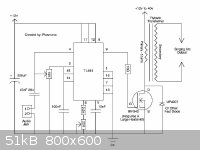
Image from: http://hackerfriendly.com/wp-content/uploads/2008/12/arc-spe...
Change the flyback to a transformer that will work for your electromagnet (rectify/filter output). Omit the capacitor to pin 4 and feed a DC control
voltage which you can find by experimenting if your not far along enough in electronics to calculate it. Just be sure the control input does not go
below zero or above the DC supply used for the IC. Also do not go too high quickly until you know what current the power mosfet will see or you may
blow it. Study how hot it gets not forgetting a proper heat sink. At least this circuit approach has a better chance working than merely ringing a
low value inductor as the link you posted does. Whether it will provide enough power I do not know as you really have not given specific enough
information. I do know this circuit can be scaled up to be the heart of a 1,500 Watt inverter for what it's worth assuming you had the DC source to
run it. Obviously you may end up building your own output transformer but this is far easier than most think it is. Many is the time I used an oven
(not too hot) to aid in pulling all the E's from an old power transformer. A bobbin you can buy or build or if careful salvage from the source (note
they melt easy). My very first HeNe laser was powered with one I built from the bad transformer from a CB base station (was around 4A/18Vac
originally). Of course if going for a high frequency from the TL494 think big ferrite transformers. Best source here is from you guessed it, a dead
old 1,500 Watt inverter. You can rewind the transformer secondary for a higher voltage but if your going to work around 110 volts it seems the
transformer from the inverter would already be perfect.
I have to wonder though why you are focused on high voltage high current circuits when something better exists. First off forget 32 gauge, go lower
voltage higher currents (heavier wire less turns). Have you looked at this video?
http://www.youtube.com/watch?v=nZL6mLISxeo
Seems like it works very well at far lower voltages meaning safer and less problematic in other areas such as heat.
Or: http://www.youtube.com/watch?v=zCsg0phiY0c
[Edited on 1-20-2014 by IrC]
"Science is the belief in the ignorance of the experts" Richard Feynman
|
|
|
elementcollector1
International Hazard
Posts: 2684
Registered: 28-12-2011
Location: The Known Universe
Member Is Offline
Mood: Molten
|
|
The magnet I wish to levitate can be of any size, so long as it can be levitated from over 6" away... In that case, I'm not sure whether lighter or
heavier is good.
Problem with lower gauge wire is way too high current - for example, 10 ft. of 12 AWG wire and 1.5V leads to 94 amps, something I definitely don't
want to mess with.
A major concern is size restraints - given that the end objective is a sort of literal realization of a video game prop, consider the model below:
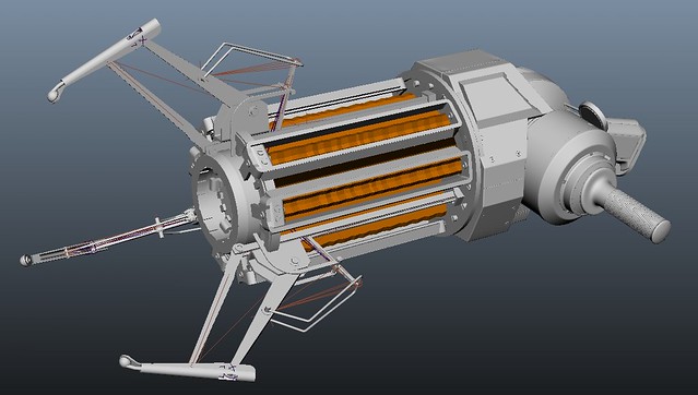
See that claw-shaped thing on the upper left? It's about 6 inches long, and that is where the magnet has to fit (without being too visibly intrusive -
I'm fine with a bit of iron core sticking out the end, but not a 2" fat solenoid...). Add that with the fact that the object should be levitated about
6" below (the center of the barrel), and this complicates things severely. Of course, I'm not going to give up - that would be no fun.
In the center, where the barrel is, I'm planning to have another electromagnet - this one attracts a spring and an aluminum plate. When the button is
pressed, the magnet is turned off, the spring flies forward, and assuming there's an object floating there, Newton's 3rd law takes care of the rest.
For this magnet, I'm probably going to use thick wire and low voltage.
Now, what I could do is wind about 1000 ft. of 32 AWG wire onto a very small nail. Most of this nail would be hidden from sight under that claw thing,
but a bit would be sticking out (the nail would be vertical, for the most part, in compliance with what you said about the field earlier). Then, I
would build a boost converter (shown here: http://www.instructables.com/id/DC-Boost-Converter/) to bring the voltage up to 110 V. Assuming the power supply is decent (i.e. lasts a hell of a
lot longer than a 1.5V battery would), the amperage would now be 0.67 A and the power would be 73.7 watts. Would this be a more reasonable power?
(And yes, I am such a nerd.)
[Edited on 1-20-2014 by elementcollector1]
Elements Collected:52/87
Latest Acquired: Cl
Next in Line: Nd
|
|
|
IrC
International Hazard
Posts: 2710
Registered: 7-3-2005
Location: Eureka
Member Is Offline
Mood: Discovering
|
|
It would take many calculations to answer. More than I have time to do especially by guessing about details and parameters from a distance. I think
you need to be building at least the coils and circuitry and experimenting.
"Science is the belief in the ignorance of the experts" Richard Feynman
|
|
|
elementcollector1
International Hazard
Posts: 2684
Registered: 28-12-2011
Location: The Known Universe
Member Is Offline
Mood: Molten
|
|
Hmm. I have 50 feet of that same 32 AWG wire on my coil, and I was wondering. If I cut this off now, the current would be 0.73 amps, and the power
would be 4.4 W. Is this any better than scaling up to 1000 feet, using a boost converter to increase the voltage to 110 V, only to get the same
current (with much more turns and a much fatter solenoid)?
I guess what I'm asking is, which is more important? Current or number of turns? I know the magnetic field is proportional to both, but I'd like to
ask those who have experimented.
Elements Collected:52/87
Latest Acquired: Cl
Next in Line: Nd
|
|
|
IrC
International Hazard
Posts: 2710
Registered: 7-3-2005
Location: Eureka
Member Is Offline
Mood: Discovering
|
|
If I had to make a guess without doing any research I would say go with more turns higher voltage. The simple reason being at fewer turns the required
current is much greater and it is the current and resistance giving rise to heating and materials problems. For the very same reason large energy
levels are transmitted long distances by upping the voltage/lowering the current and therefore reducing both heating and loss effects. Of course
depending upon the field strength you require as well as considering various limitations involved. Possibly you could experiment with both approaches
on a small scale just to get an idea which route would be better. Make a couple test coils and measure field strength, energy input, heating and so
on. Unless of course you do not have access to the wire to wind from several hundred to a few thousand turns.
"Science is the belief in the ignorance of the experts" Richard Feynman
|
|
|
elementcollector1
International Hazard
Posts: 2684
Registered: 28-12-2011
Location: The Known Universe
Member Is Offline
Mood: Molten
|
|
Tested boost converter circuit today. Appears to work fine, with the drawback that the MOSFET heats up severely - 5-10 seconds, and it burns to the
touch. Should I use aluminum for a large heat sink for this? (large being a 3"-by-1"-by-1" rectangular prism.) I am really worried about the MOSFET
burning out from such heat, as it would be hard to replace - both in terms of the circuit and the cost.
The electromagnet seems to be quite a bit stronger. Not sure if this is quite enough to levitate objects, and I haven't tested the voltage or current
or anything. A cursory test with picking up LEDs (comparing to counts from earlier variations of the magnet) showed that it's at least as good as
before, if not better.
Elements Collected:52/87
Latest Acquired: Cl
Next in Line: Nd
|
|
|
IrC
International Hazard
Posts: 2710
Registered: 7-3-2005
Location: Eureka
Member Is Offline
Mood: Discovering
|
|
Adequate size heat sink is mandatory. If you paint it flat black (not glossy) it will radiate around 25 percent more heat which helps quite a bit.
Anodized black is better but if it is not handy the flat black trick works fine. Along with a thin coat of thermal compound of course. Rule of thumb
is if sink is adequate you can hold your palm against it for 30 seconds without discomfort although I do not recommend this test if powered by
dangerous voltages. Really I am just giving you an idea how hot is too hot meaning bigger sink and/or reduced duty cycle to the waveform, also reduced
voltages helps. Just mentioning the common sense ideas.
"Science is the belief in the ignorance of the experts" Richard Feynman
|
|
|
elementcollector1
International Hazard
Posts: 2684
Registered: 28-12-2011
Location: The Known Universe
Member Is Offline
Mood: Molten
|
|
Voltage confirmed at 150 volts, but it doesn't last long - it quickly drops back down to about 6V or so. Why is this? Is it the MOSFET overheating?
Elements Collected:52/87
Latest Acquired: Cl
Next in Line: Nd
|
|
|
IrC
International Hazard
Posts: 2710
Registered: 7-3-2005
Location: Eureka
Member Is Offline
Mood: Discovering
|
|
Insufficient data for a meaningful reply. Sounds like a reasonable assumption.
I should probably add you know there is no way someone from a distance can answer anything without an exact circuit with parts list, including what
it's powered by and loaded with. All measurements and so on. Measuring field could be a simple compass mounted a distance away comparing deflection.
Assuming you do not lay a pile of bolts between the coil and compass or make other alterations.
[Edited on 1-27-2014 by IrC]
"Science is the belief in the ignorance of the experts" Richard Feynman
|
|
|
elementcollector1
International Hazard
Posts: 2684
Registered: 28-12-2011
Location: The Known Universe
Member Is Offline
Mood: Molten
|
|
(Questions and concerns are bolded so they're easier to find.)
Have since wired a much better coil:

This one is as strong as it's predecessors, with much less size and length of wire - and that's *without* the boost converter. *With* the boost
converter, this could be the lucky combination of amps and wire turns I've been looking for. Of course, the heat produced would be severe unless I
used some sort of heat sink - 2 A of current running through about 460 feet of magnet wire cannot be good for it.
This comes into my next question/problem: I talked to a physics professor, and he said the system with the large electromagnet and the spring/aluminum
rod would *not* work, because the spring (being welded to the core) would now have a pole of the magnet at its tip, and that pole would want to
distance itself from the other pole at the end. He suggested instead to use a railgun as the launcher of choice.
So, I would have to construct a railgun with an H-Bridge circuit. The aluminum rod would now be attached to the 'roller' (an iron nail and two
disc-shaped Nd magnets as wheels), and allowed to rotate (this way it would roll forward while still keeping the aluminum rod pointed forward). The
railgun would naturally require a capacitor bank, and a high source of current.
I am hoping that the use of the railgun, and the subsequent charging of the capacitors will use enough energy to lower the current through the
first set of electromagnets (as there are now 3, explained below) to a more heat-tolerable level. The railgun and electromagnets would all
run off the same power source, and the railgun would possibly run off the same boost converter as the electromagnets, depending on what power
consumption is needed.
The reason there are now 3 electromagnets out in the front is because I realized that vertical levitation will not be enough to keep this in the air,
as the slightest oscillation or gust of wind would cause it to leave the affecting field. To fix this, I would put 2 more electromagnets on the two
other 'claws' (see the image a few posts up). These would face the center of the barrel, same as the first electromagnet (keep in mind that these are
exactly 120 degrees apart), and have the same configurations (Hall Effect sensors, logic-level MOSFET controls and all), and the same basic purpose:
If the electromagnet moves too far away from either of them, they will pull it back towards the center. This ought to lessen the effects of
horizontal interference, right? The magnet can still escape, but it is harder to do so. Hopefully, I'll be able to pick this thing up without
the magnet escaping - that is the goal, after all.
Elements Collected:52/87
Latest Acquired: Cl
Next in Line: Nd
|
|
|
| Pages:
1
2 |


