subsecret
Hazard to Others

Posts: 424
Registered: 8-6-2013
Location: NW SC, USA
Member Is Offline
Mood: Human Sadness - Julian Casablancas & the Voidz
|
|
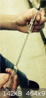
Bromine Spectrum Tube
This is a bromine tube that I found at my local education supply store... In the instructions, it says that it starts with 4kV and runs at 1kV. Would
a fluorescent tube ballast work to run this tube? I also have a neon sign transformer with an output of 15kV at 30mA. Would personal damage occur if
the tube was used with this transformer?
Any help is appreciated.
Fear is what you get when caution wasn't enough.
|
|
|
IrC
International Hazard
Posts: 2710
Registered: 7-3-2005
Location: Eureka
Member Is Offline
Mood: Discovering
|
|
No, No, probably - also ruin tube rapidly. In that order. Try to find out how many ma at 1KV is normal operation. Also is the trigger applied to a
metalized coating or is it applied to one of the operating terminals (end of tube). I wouldn't risk ruining a hard to find neat tube like that.
"Science is the belief in the ignorance of the experts" Richard Feynman
|
|
|
12AX7
Post Harlot
Posts: 4803
Registered: 8-3-2005
Location: oscillating
Member Is Offline
Mood: informative
|
|
I would hazard a guess that the NST would work, but as IrC says, better safe than sorry!
Hmm, wonder what the electrodes are. Guessing they aren't ordinary nickel or stainless steel. Is Mo resistant to Br? (And at what temperatures...)
Pt or Ir would certainly do it, but....man....
Tim
|
|
|
IrC
International Hazard
Posts: 2710
Registered: 7-3-2005
Location: Eureka
Member Is Offline
Mood: Discovering
|
|
I probably should have mentioned the correct resistance in series would work with the NST but didn't because of the terrible dissipation heat dropping
thousands of volts even at a few ma. Also one would still need to know the safe current and a trigger pulse would also be needed. Wonder what it would
do with a coil around it with a few watts of RF.
"Science is the belief in the ignorance of the experts" Richard Feynman
|
|
|
12AX7
Post Harlot
Posts: 4803
Registered: 8-3-2005
Location: oscillating
Member Is Offline
Mood: informative
|
|
Could also try a dimmer on the NST, but that would require one that can handle inductive loads. Or a dimmable NST module to begin with -- I think
they exist, but aren't too common..?
RF would probably do well... got a Tesla coil or plasma globe?
A supply like an NST, or the equivalent DC, is probably what it needs. I wouldn't be worried about ignition, at least on a supply like that. If you
went after other means, of course, it might be important.
Tim
|
|
|
Pyrotrons
Harmless
Posts: 38
Registered: 13-10-2013
Member Is Offline
Mood: No Mood
|
|
Seriously, just put your NST across it. NST's are inherently current limited. Those electrodes look like standard gas tube electrodes.
EDIT: removed the middle part, I failed to read the spec's on your NST. Your NST is perfect for this, so perfect in fact, that I imagine you could
leave it on the bulb for years.
There is absolutely no way that you can harm this device with a *30mA* NST, unless you drop the transformer on it.
[Edited on 6-11-2013 by Pyrotrons]
[Edited on 6-11-2013 by Pyrotrons]
"Thus ethyl alcohol is inferior to xylene, although usable for certain applications." - Gerald Hurst
|
|
|
IrC
International Hazard
Posts: 2710
Registered: 7-3-2005
Location: Eureka
Member Is Offline
Mood: Discovering
|
|
Quote: Originally posted by Pyrotrons  | Seriously, just put your NST across it. NST's are inherently current limited. Those electrodes look like standard gas tube electrodes.
EDIT: removed the middle part, I failed to read the spec's on your NST. Your NST is perfect for this, so perfect in fact, that I imagine you could
leave it on the bulb for years.
There is absolutely no way that you can harm this device with a *30mA* NST, unless you drop the transformer on it. |
I really hope He does not listen to your poor advice. Good spectrum tubes are a shame to waste. He would destroy it rapidly with your bad information.
Only one step away from advice which could harm members is advice which could destroy their equipment. The tube is labeled per starting post 4KV start
pulse, 1 KV operating voltage. That is about 2 watts dissipation at 2 ma. Much above 10 watts maximum the tube would not live very long and the
spectrum would not be pure. 15 KV at 30 ma is 450 watts dissipation. Are you mad? When you so positively stated 15,000 volts at 30 milliamps cannot
possibly harm it just exactly which words of His did you not read? The NST was designed to run a long tube with large light output. The spectrum tube
runs softly being designed not for visibility on the street below, rather to produce a set of lines at close range in the laboratory.
"Science is the belief in the ignorance of the experts" Richard Feynman
|
|
|
quantumchromodynamics
Hazard to Self
Posts: 67
Registered: 25-9-2013
Location: with much determination, nowhere in particluar
Member Is Offline
Mood: tired but still trying
|
|
you need a ballast
Most NSTs are 30ma current limited. In your case this is a good thing, but 30ma can easily burn up a tube. A tube like that exhibits a high impedance
before it is started. Once the tube is started the impedance goes way down. That means once the tube starts it wants more current (way nonlinear) and
thereby tries to blow itself up. That is why you drop the voltage to 1kv immediately after the tube starts. The 4kv is just a tickle. The 1kv needs
proper current limiting. You might need to wind a ballast.
Are you ratings AC or DC? Remember peak AC is 2 * sqrt(2) more volts than a flat DC voltage...
|
|
|
Pyrotrons
Harmless
Posts: 38
Registered: 13-10-2013
Member Is Offline
Mood: No Mood
|
|
Hey IrC - relax buddy!!!
Questions for you:
1. Did you imply that a 15kV 30mA neon would get 450W of power into the tube? I think you did! And then you asked if I was mad!!! HAHAHAHA!!!
2. Where did you get the 2mA figure? Just pulling that out of somewhere? Ohh.. wait...you actually assumed that the tube would be operating with
1,000V across it like the box says *headdesk*
3. Do you understand what happens to a gas as you start pulling current through it? It's resistance drops like a rock. Low resistance = low power
dissipation = low temperature rise.
For reference, this "spectrum tube" power supply pulls a current of 10mA through the tube:
"1,000V @10mA with spectrum tube"
http://www.arborsci.com/spectrum-tube-power-supply
I stand by all of my aforementioned statements, INCLUDING that 30mA is not going to hurt the tube. Might get hot. But IT'S BOROSILICATE.
"Thus ethyl alcohol is inferior to xylene, although usable for certain applications." - Gerald Hurst
|
|
|
Pyrotrons
Harmless
Posts: 38
Registered: 13-10-2013
Member Is Offline
Mood: No Mood
|
|
quantumchromodynamics, you are right, for the most part.
You are definitely correct, in that the impedance drops after start-up. It's this drop...when used with a CURRENT-LIMITED source (like a neon sign
transformer) that will keep the tube FROM exploding.
EDIT: Added the following:
(The ballast, is built into the neon transformer in the form of magnetic shunts in the core. Short the output of a neon (like a neon sign does...or a
spectrum tube...and the output will hit the current rating of the transformer. In this case, 30mA.)
[Edited on 6-11-2013 by Pyrotrons]
"Thus ethyl alcohol is inferior to xylene, although usable for certain applications." - Gerald Hurst
|
|
|
quantumchromodynamics
Hazard to Self
Posts: 67
Registered: 25-9-2013
Location: with much determination, nowhere in particluar
Member Is Offline
Mood: tired but still trying
|
|
extra ballast
Pyrotrons: not exactly...
The shunts in an NST are designed to keep the NST from exploding, not the tube. His NST will likely dump 30ma @ 15kv into the tube, delivering 450
watts, and blow up the tube.
To further restrict current to the tube I suggest winding an additional ballast. Place the ballast in series with the NST. A variac in front of the
NST can be used to creep the voltage.
Do not use a lamp dimmer!
|
|
|
IrC
International Hazard
Posts: 2710
Registered: 7-3-2005
Location: Eureka
Member Is Offline
Mood: Discovering
|
|
I find it amazing in this internet age how little some people bother spending time actually searching for correct information in lieu of cavalierly
guessing what advice to post. Spectrum tubes are very delicate devices. The absolute maximum voltage which the tube can withstand before ionization is
5,000 volts, and the recommended safe maximum is 4,000 volts. That is assuming any of you expect to use it for more than a few seconds. The peak
voltages of your constant talk of 15,000 volt transformers will I assure you destroy the tube rapidly. Until the few microseconds before ionization
drops this voltage the damage is done. Tim's idea of controlling the AC input to an NST was the only idea capable of working safely as long as the
input voltage never exceeded 32 VAC and upon full ionization the current never exceeded 10 ma for 30 seconds. In simple terms, enough of the NST
advice.
Upon ionization of the gas the voltage must be no more than 1,000 volts at an absolute maximum of 10mA. Even then if you value the tube you must not
let it run more than 30 seconds, then keeping it off for 30 seconds. Assuming you design the supply with all these constraints the tube can safely run
for many hours. 30 seconds on, 30 off, repeat. Exceed any one of these specifications say goodbye to your roughly $50 tube.
What I am getting from the replies to this thread is the knowledge that none of you have ever actually operated a spectrum tube nor do you know
anything about them. I have used an old HeNe laser supply with a 220K 2W resistor in series but the tube ran a little too hot so even this is not the
best idea. Not wishing to ruin the set I have and being too cheap to buy a factory supply I never played with them all that much. However this thread
prompted me to do some in depth research and study of available information including the current controlled supply.
There is a reason they carefully control the gas pressure in each spectrum tube VS the element being observed. Proper light output and clarity of the
spectral lines. A few excessive arcs inside and not only can the pressure be affected but the chance of metal ions floating in the tube could wreck
the purity of the spectrum being observed. We are not talking about how to help Awesomeness power a desk lamp. The idea was to operate it as intended
with a useful clean spectral output and hopefully a long lifetime.
"I stand by all of my aforementioned statements"...
I wouldn't brag about it, at least QC is trying to look thoughtfully at the question using knowledge and common sense.
[Edited on 11-6-2013 by IrC]
"Science is the belief in the ignorance of the experts" Richard Feynman
|
|
|
quantumchromodynamics
Hazard to Self
Posts: 67
Registered: 25-9-2013
Location: with much determination, nowhere in particluar
Member Is Offline
Mood: tired but still trying
|
|
" It's resistance drops like a rock. Low resistance = low power dissipation = low temperature rise."
The above statement is incorrect.
Resistance drops, more current surges in, higher power dissipation, higher temperatures, the tube blows up.
Add a ballast after the NST to further restrict current. Use a variac to adjust NST voltage.
Do not use a lamp dimmer!
|
|
|
Pyrotrons
Harmless
Posts: 38
Registered: 13-10-2013
Member Is Offline
Mood: No Mood
|
|
<b>IrC</b>, you said:
"The peak voltages of your constant talk of 15,000 volt transformers will I assure you destroy the tube rapidly"
Then why don't you tell me HOW CAN ONE BE SUCCESSFULLY POWERED WITH A 30cm-ARC TESLA COIL? Oh wait, you haven't done that?! I have. Old spectrum
tube from back-of-the-lab in college, Deuterium, my tesla coil. 15 years ago.
<b>IrC</b>, you wrongly flamed me for giving incorrect information, then gave a huge load of it yourself.
And why are you not answering my three technical questions?
quantumchromodynamics:
Resistance drops, <b><i>more current surges in</b></i>, higher power dissipation, higher temperatures, the tube blows up.
Again, there is a current LIMIT at 30mA. 30mA cannot be exceeded. You can put a GOLD BAR across the output insulators of the neon transformer and it
will not pull more than 30mA. The neon is internally ballasted. This isn't a normal transformer man.
I do agree about not using a light dimmer...
"Thus ethyl alcohol is inferior to xylene, although usable for certain applications." - Gerald Hurst
|
|
|
woelen
Super Administrator
Posts: 7977
Registered: 20-8-2005
Location: Netherlands
Member Is Offline
Mood: interested
|
|
I have to agree with IrC, and he is right! The tube will be destroyed quickly if 30 mA is running through it. Of course, it will not have the full
voltage of the NST, the voltage will drop when the tube is going at full current, but I'm quite sure that the voltage will be higher than when 2 mA is
flowing through the tube. So, at 30 mA you will not have a dissipation of 450 W, but a dissipation of the order of magnitude of 50 W certainly is
imaginable and that dissipation WILL destroy the tube in a short time, it simply becomes very very hot.
I would try to find a high frequency power supply, running at 15 kHz or something like that, from an old PC-monitor or old TV (unfortunately, the
newer monitor types do not have such a nice high voltage generator in them anymore) and use a series load to limit the current, while at the same
time, as long as the tube is not lit, the high voltage will ignite the tube. You need to tap the HV before the rectifier, you need AC! IrC most likely
can tell more about the required characteristics of the series load, probably an inductor of suitable value will do, but I can imagine that addition
of some series resistance may help reduce formation of very high voltage peaks when the inductor goes 'on' at once.
[Edited on 6-11-13 by woelen]
|
|
|
IrC
International Hazard
Posts: 2710
Registered: 7-3-2005
Location: Eureka
Member Is Offline
Mood: Discovering
|
|
| Quote: Originally posted by Pyrotrons | <b>IrC</b>, you said:
"The peak voltages of your constant talk of 15,000 volt transformers will I assure you destroy the tube rapidly"
Then why don't you tell me HOW CAN ONE BE SUCCESSFULLY POWERED WITH A 30cm-ARC TESLA COIL? Oh wait, you haven't done that?! I have. Old spectrum
tube from back-of-the-lab in college, Deuterium, my tesla coil. 15 years ago.
<b>IrC</b>, you wrongly flamed me for giving incorrect information, then gave a huge load of it yourself.
And why are you not answering my three technical questions?
quantumchromodynamics:
Resistance drops, <b><i>more current surges in</b></i>, higher power dissipation, higher temperatures, the tube blows up.
Again, there is a current LIMIT at 30mA. 30mA cannot be exceeded. You can put a GOLD BAR across the output insulators of the neon transformer and it
will not pull more than 30mA. The neon is internally ballasted. This isn't a normal transformer man.
I do agree about not using a light dimmer... |
The Tesla coil had such a low current in likely the microamp range that it neither altered gas pressure nor blasted metal ions from the electrodes
into the tube. This is why it could be in excess of safe maximum voltages and not damage the tube. It is an old trick many science teachers have used
for years. Problem is if one wishes the output intensity and spectral purity to be useful for any scientific work rather than quick classroom
demonstrations, one uses the proper supply and never subjects the tube to anything outside design specifications.
[Edited on 11-6-2013 by IrC]
"Science is the belief in the ignorance of the experts" Richard Feynman
|
|
|
watson.fawkes
International Hazard
Posts: 2793
Registered: 16-8-2008
Member Is Offline
Mood: No Mood
|
|
Since nobody here has so far mentioned the distinction between glow discharge and arc discharge, it's time to learn the difference. Here's a decent exposition on the subject. Since I don't anticipate everyone yammering here will bother to read this, here are a couple of salient sentences:
| Quote: |
The arc discharge is a high-current, low-voltage discharge, in contrast with the low-current, high-voltage glow discharge. It is characterized by a
negative-resistance V-I characteristic, and high temperatures. |
Spectrum tubes operate with glow discharge.
If you put a spectrum tube into arc discharge mode, you'll destroy it. Apparently some here don't know about glow discharge at all, and assume that
every discharge is an arc discharge, like this guy: | Quote: Originally posted by Pyrotrons | | 3. Do you understand what happens to a gas as you start pulling current through it? It's resistance drops like a rock. |
That's the "negative-resistance V-I characteristic" referred to in the reference, and that's relevant to arc discharge and not glow
discharge.
As far as power supplies, it's useful to remain aware that spectrum tubes are standardized to use a common power supply regardless of composition
inside the spectrum tube. For anybody that wants to develop a power supply, I'd recommend picking up a cheaper spectrum tube than for bromine; for
example, Amazon has a number in the $18-22 range: H, He, O2, N2, CO2, Ne, Ar, etc. That way, when you fry your first tube, it's a less expensive
mistake.
I couldn't find a schematic for a supply with a moderate-effort search, but the basic operating specs for the commercial ones provide a clue. They
seem to have open circuit voltages of 5 kV and operate at 1 kV and 10 mA current draw, for a 10 W glow discharge. (10 W of power is perfectly adequate
power dissipation for a small tube such as these.) I'd guess that these supplies are smallish Cockcroft-Walton multipliers. These have the property
that they can have quite high open-circuit voltages and yet droop quite a lot when they're put under load. The secret to designing this behavior is
not to overspec the capacitors in the multiplier. There's plenty on the internet about designing such circuits, and anybody working one one would need
to do a few design calculations. If I were designing one, I'd use a transformer built to supply plate voltage with secondary in the 300 - 400 V range
and look at a multiplier with 12 - 16 stages. Using a transformer provides isolated power (always a good thing) and using this secondary voltage
allows standard 1 kV diodes (1N4007) in the multiplier.
Edit: Corrected diode part number; see IrC's comment below.
Edit 2: I implicitly made the assumption that the spectrum tube has internal electrodes and the supply was DC. External electrodes and AC supplies
have also been built; power is coupled capacitively through the glass tube ends. I realized I have never looked closely at the tubes before.
[Edited on 2013-11-6 by watson.fawkes]
|
|
|
IrC
International Hazard
Posts: 2710
Registered: 7-3-2005
Location: Eureka
Member Is Offline
Mood: Discovering
|
|
That was a good read watson, thanks. Have not seen a work on this subject since studying Pulsed Abnormal Glow Discharges, although I doubt the
Correa's ever went on to produce much of what they hoped for. The capacitors I saw in one I looked at were 3,300 pF/3KV for what it's worth. Also,
just a minor correction but the number is 1N4007 not 1N1007. A 1N1007 was a 380V PIV, 350mA, Germanium rectifier, not a common 1 ampere 1KV PIV
silicon rectifier which is what I know you meant to say.
That was odd, looking at the number thinking diode my brain said 1 when you said 2. Oh well we both know you meant 1 (diode), not 2 (transistor).
2N1007 is a PNP Ge 50V/10 ampere TO3 audio transistor.
Anyway we know what you meant. Here is more information:
http://www.plasma-universe.com/Electric_glow_discharge
[Edited on 11-6-2013 by IrC]
"Science is the belief in the ignorance of the experts" Richard Feynman
|
|
|
unionised
International Hazard
Posts: 5104
Registered: 1-11-2003
Location: UK
Member Is Offline
Mood: No Mood
|
|
OK, a couple of points.
A 15KV NST rated for 30 mA will deliver 30mA or 15KV, but not both.
It would put pretty close to 30mA through that Br2 tube and that's a lot more current than it was built to handle.
The voltage across it might be near 1000 V at the rated current of 10mA
If you want to run that tube from that transformer you need a current limiting resistor.
Essentially the current needs to be held to - say 5 mA while drawing most of the 15Kv
1 mA would take 15M ohms
5 mA would need 3M ohms
It would dissipate about 75 Watts and have to stand off 15KV so it's not just any old cheap resistor.
You could use that NST but it might be easier to use a CCFL driver of the sort used in PC case modding.
|
|
|
IrC
International Hazard
Posts: 2710
Registered: 7-3-2005
Location: Eureka
Member Is Offline
Mood: Discovering
|
|
unionised "might be easier to use a CCFL driver of the sort used in PC case modding."
Best advice thus far. I am sure the modern supplies use PWM and a TL494, ferrite transformer inverter circuit, PWM allowing accurate control of the 10
ma maximum. This appears to be evident from typical facts like using a wall wart, 35 watts power input, running on 12 VDC, looking at the size of the
supply, the fact that most manufacturers use what is cheap, common, rely on published example circuits from data sheets, and etc.. From reverse
engineering many similar circuits this route appears to be most common today.
"Science is the belief in the ignorance of the experts" Richard Feynman
|
|
|
unionised
International Hazard
Posts: 5104
Registered: 1-11-2003
Location: UK
Member Is Offline
Mood: No Mood
|
|
Not sure if a ccfl would provide the starting voltage needed.
|
|
|
watson.fawkes
International Hazard
Posts: 2793
Registered: 16-8-2008
Member Is Offline
Mood: No Mood
|
|
They would have some higher starting voltage.
Glow discharge is generally preceded by some amount of initial corona discharge, and this occurs at a higher voltage than the glow discharge.
If I were making a lab instrument, however, I'd make a supply that was more tunable than a COTS supply for CCFL (and likely also more monitorable).
The C-W multiplier I suggested above could be paired (simply) with a small variac, or (less simply) supplied by a custom boost-mode switcher. It would
also be a good idea to integrate a four-wire current-sense resistor on the output terminal with a crowbar protection circuit (caution: needs an
opto-isolator!).
|
|
|
IrC
International Hazard
Posts: 2710
Registered: 7-3-2005
Location: Eureka
Member Is Offline
Mood: Discovering
|
|
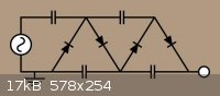
Just do it exactly the same way we built HeNe supplies back in the 80's, only 1 KV instead of 1,750 volts when the tube is operating. Use a
Cockcroft–Walton multiplier to power the tube since it would by design give a perfect starting pulse. In the first few microseconds a several
kilo-volt pulse hits the tube, when the glow discharge begins the voltage settles down to 1,000 assuming you design the circuit properly for the
needed conditions. Putting series resistance in the ground end of the tube can provide a voltage to use as feedback information as to current flow.
Just adjust the circuit to limit maximum current to 10 ma at 1KV. Selecting the proper capacitors in the multiplier stage will give the needed 4 to 5
KV starting pulse. Nothing could be simpler and it would operate quite reliably once you had all the parameters correct for your tube. This is not a
difficult design problem if you think about it. If I had to guess I would say 1 nf capacitors (to 3.3 nf) and 1N4007 dodes wired as in the image below
would work fine. Of course assuming the tube runs well on DC. Having never owned a factory built supply I am not sure if they are AC or DC output. I
do not think it would be a problem as DC is all I ever tried for my tubes (an old laser supply which I admit was nearly twice the proper voltage), hot
tubes, also why I never really played with them much. Interesting discussion, if I have time and inclination maybe I should take the time to
experiment building my own. The last question I do not know, must it be an AC supply or will DC work well? If AC then your right design will be more
complicated as far as the trigger pulse goes.
http://en.wikipedia.org/wiki/Cockcroft%E2%80%93Walton_genera...
"Science is the belief in the ignorance of the experts" Richard Feynman
|
|
|
Morgan
International Hazard
Posts: 1662
Registered: 28-12-2010
Member Is Offline
Mood: No Mood
|
|
Four spectrum tubes running on one hand.
http://www.youtube.com/watch?v=ILOuL4RK-6I
Viewer comment.
"Great video jay but that not good for your body to do that a lot, it will have side effects."
|
|
|
Morgan
International Hazard
Posts: 1662
Registered: 28-12-2010
Member Is Offline
Mood: No Mood
|
|
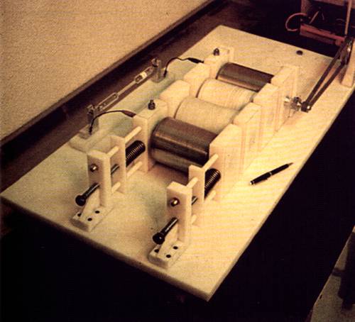
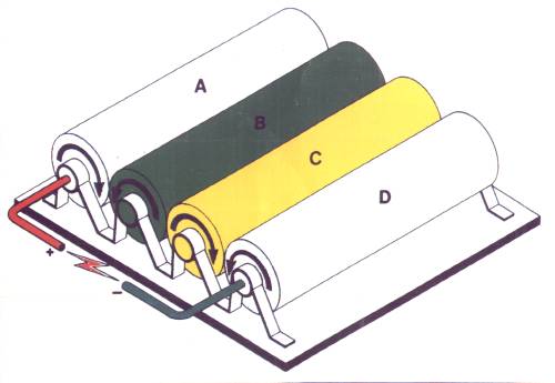
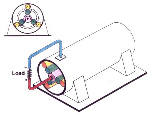
I just noticed this spectrum tube being run by a Lorente generator.
"A triboelectric machine composed of four cylinders that roll together without friction, under a slight pressure. The two outermost cylinders are
metallic, and the two central cylinders are of distinct insulating materials (nylon and teflon). Opposite charges are collected in the metallic
cylinders. The basic machine produces voltages of some tens of kV, but several modules can be stacked for more voltage."
http://www.coe.ufrj.br/~acmq/lorente4.jpg
http://www.coe.ufrj.br/~acmq/lorente1.jpg
Coaxial version http://www.coe.ufrj.br/~acmq/lorente2.jpg
The Lorente information came from the friction machine devices near the bottom of that category.
http://www.coe.ufrj.br/~acmq/electrostatic.html
Advantages
"Due to its simplicity in design, Lorente´s Generator is not exposed to maladjustments or failures. Every operator knows the difficulty of making the
"mise au point" of some classical electrostatic machines."
In the first diagram "load or sparkle" ha
http://info.uned.es/electrostatic-generator/index.html
|
|
|
Texium
|
Thread Moved
21-11-2023 at 13:43 |


