| Pages:
1
2
3
4
..
9 |
Magpie
lab constructor

Posts: 5939
Registered: 1-11-2003
Location: USA
Member Is Offline
Mood: Chemistry: the subtle science.
|
|
Thanks diddi for all that great information. It sounds like I am well on my way to getting a variable speed stirrer. This is not my main hobby
interest but I do enjoy learning about it and then making something useful for chemistry.
I was just blown away when I tore into that huge Savin 3515 copier - it looks like an engineering marvel. I almost feel guilty about taking it apart.
I think you are telling me to scavenge a volume dial as a variable resistor. If I can't find one I can always buy a potentiometer from Radio Shack.
That would work wouldn't it?
I see that they have those nice little plastic "breadboards" at RS also. I would need something like that too - right?
Are you saying you could post a circuit schematic? I think that would be very helpful to me as well as others.
I will continue my salvage operation tommorrow. I'm expecting to find a real cornacopia. 
edit: copier brand name
[Edited on 3-11-2014 by Magpie]
The single most important condition for a successful synthesis is good mixing - Nicodem
|
|
|
diddi
National Hazard
Posts: 723
Registered: 23-9-2014
Location: Victoria, Australia
Member Is Offline
Mood: Fluorescent
|
|
I can post an actual PCB diagram so you can make a circuit board. the plastic prototype board is called a "breadboard" they are available cheap at
dx.com
http://www.dx.com/p/solderless-breadboard-white-large-size-1...
they are not good for end users and I would discourage you from using one as your "real" version. great as prototype. they do not provide reliable
connections and are not meant to be permanent. you would only need a cheap soldering iron to recover the parts you need from a power supply. don't
try to pry them off. and you could solder up the project in no time once you have made a PCB. pics later when I get home.
|
|
|
Magpie
lab constructor
Posts: 5939
Registered: 1-11-2003
Location: USA
Member Is Offline
Mood: Chemistry: the subtle science.
|
|
I do have a soldering iron, solder, etc. I have assembled a Heathkit volt-ohm meter so do have some experience with electronics assembly. I look
forward to your pictures and thank you again.
The single most important condition for a successful synthesis is good mixing - Nicodem
|
|
|
diddi
National Hazard
Posts: 723
Registered: 23-9-2014
Location: Victoria, Australia
Member Is Offline
Mood: Fluorescent
|
|
have you etched your own PCBs? its a bit of chemistry
|
|
|
Magpie
lab constructor
Posts: 5939
Registered: 1-11-2003
Location: USA
Member Is Offline
Mood: Chemistry: the subtle science.
|
|
No. I did make a circuit for controlling my tube furnace as shown here: http://www.sciencemadness.org/talk/viewthread.php?tid=9705&a...
and that's about it.
The single most important condition for a successful synthesis is good mixing - Nicodem
|
|
|
Magpie
lab constructor
Posts: 5939
Registered: 1-11-2003
Location: USA
Member Is Offline
Mood: Chemistry: the subtle science.
|
|
hi diddi: I finished tearing down the Savin 3515 copier today (not an HP). I salvaged the big circuit boards and other stuff that looked
interesting. My garbage can is nearly full. Now on to the computers.
I looked at the data sheet you linked and tried to identify which motor I have. Mine weighs 298g. So with the amp and resistance values I can sort
of determine which motor I have.
I am puzzled by the rating of 3.1v on the motor nameplate then on data sheet frequency-torque graphs it indicates 24.0v. What does this mean? Why
the difference?
How do you relate the frequency value to actual shaft rpm?
I have a computer power supply from my old Gateway that I tore down a number of years ago. It will supply both 5vdc and 12vdc. Would this be a
suitable power supply?
[Edited on 4-11-2014 by Magpie]
[Edited on 4-11-2014 by Magpie]
The single most important condition for a successful synthesis is good mixing - Nicodem
|
|
|
diddi
National Hazard
Posts: 723
Registered: 23-9-2014
Location: Victoria, Australia
Member Is Offline
Mood: Fluorescent
|
|
5VDC is perfect for logic side of the project (as per my diagram) and depending on the stepper, it may be good to use 12vdc. are there any
indentifying numbers on the stepper. it sounds like your motor only has 2 wires? which is not a stepper.
the capacitors you want will look like this:
http://www.tandyonline.co.uk/components/capacitors/electroly...
you need at least 25V and about 10-47uf
|
|
|
Magpie
lab constructor
Posts: 5939
Registered: 1-11-2003
Location: USA
Member Is Offline
Mood: Chemistry: the subtle science.
|
|
I definitely have a stepper. Nameplate information is as I listed above, ie:
MINEBA "ASTROSYN" STEPPER, type 17PM-J802-G1VS; NO. T5815-01 A; DWG NO. AX05 0204 A; 3.1V; 1.14A; 1.8 deg
This motor is a cube about 2" on a side w/laminations; there's 6 wires coming off from a plug-in.
The single most important condition for a successful synthesis is good mixing - Nicodem
|
|
|
diddi
National Hazard
Posts: 723
Registered: 23-9-2014
Location: Victoria, Australia
Member Is Offline
Mood: Fluorescent
|
|
oh that's the one from the HP copier. the other one you describe does not sound like one tho. all good
|
|
|
Magpie
lab constructor
Posts: 5939
Registered: 1-11-2003
Location: USA
Member Is Offline
Mood: Chemistry: the subtle science.
|
|
That's right diddi. But I did make a mistake in calling it an HP copier- it was a Savin 3515 - not that that makes any difference.
I just finished tearing down the Dell computer. Not much of value in it - just a couple small heat sinks and a fan. There was no power supply in it
- no wonder it was junked. 
One more computer to tear down - an "emachines." Then I'm done with my salvaging.
The single most important condition for a successful synthesis is good mixing - Nicodem
|
|
|
diddi
National Hazard
Posts: 723
Registered: 23-9-2014
Location: Victoria, Australia
Member Is Offline
Mood: Fluorescent
|
|
and you trashed the rest of the Dell....
along with the gold on all the connectors and memory modules and on/in CPU
and the tantalum and silver in the SMD capacitors 
|
|
|
Magpie
lab constructor
Posts: 5939
Registered: 1-11-2003
Location: USA
Member Is Offline
Mood: Chemistry: the subtle science.
|
|
Actually I saved the large circuit board in case there might be resistors/capacitors/inductors that I need. I also saved the drives but have no idea
why.
I know you are joking, but I won't be attempting to reclaim any precious metals
Edit 1: I finished tearing down the eMachine computer. Again the power supply was gone  . I did get a large heat sink and a large circuit board w/capacitors/resistors/inductors. Out of all this teardown I only found 1
sizeable stepper motor. But not to worry, RS is nearby and everything is available online. . I did get a large heat sink and a large circuit board w/capacitors/resistors/inductors. Out of all this teardown I only found 1
sizeable stepper motor. But not to worry, RS is nearby and everything is available online. 
Edit 2: Apparently I did get a power supply out of the Dell. It looked so different from that from my Gateway that I did not recognize it.
[Edited on 5-11-2014 by Magpie]
[Edited on 5-11-2014 by Magpie]
The single most important condition for a successful synthesis is good mixing - Nicodem
|
|
|
diddi
National Hazard
Posts: 723
Registered: 23-9-2014
Location: Victoria, Australia
Member Is Offline
Mood: Fluorescent
|
|
not joking: I get everyone I know to dump their ewatse with me. I have about 5grams of gold and 20grams of silver from ewaste in maybe 20 hours of
leisurely dismantling and a bit of chem.. the hard drive has a very nice NdFeB magnet (or maybe 2) a small stepper and a good amount of gold; and the
chassis is solid Al. the screws are stainless steel machine screws top quality.
heatsinks are good quality Al that brings better scrap value. I just fill my tub and cash it in now and then. got about $100 last time
|
|
|
Magpie
lab constructor
Posts: 5939
Registered: 1-11-2003
Location: USA
Member Is Offline
Mood: Chemistry: the subtle science.
|
|
Nice work on the metal reclaiming diddi. Yes, I did know that there would be a nice Nd magnet in the hard drive as I saved the one from my old
Gateway.
I did a little research online for availability and price for the needed components. One thing I learned from my previous component purchases was
try to order all of them from one supplier Otherwise postage will kill you. So, I arbitrarily looked at Digi-Key. Here's what I found:
counter: IC OSC UP/DOWN CNTR; Digi-Key No.: ICM7217IPI+-ND; mfg: Maxim Integrated; 2MHz 28-DIP; $9.93
electrolytic capacitor: 47uF, 35V, Nichicon No.: UVRIV479MDD1TA ; aluminum; 20%; radial; $0.27
IC motor driver: Allegro MicroSystems No.: A4988SETTR-T; PAR 28QFN; general purpose; supply voltage:3v-5.5v; voltage-load: 8v-35v; $3.28
As a point of interest, the stepper motor I salvaged goes for at least $50.
Some questions:
1. Would you have to take the counter reading difference over a given time period to determine the rpm? What exactly is being counted?
2. The driver block diagram shown in the link you provided indicates that a "microcontroller" is required. Is this really needed for this
application? If so, what is this?
3. You indicate that a resistor is needed. Is this where the pot comes in for variable speed? If so, what would be the resistance value of said
pot?
[Edited on 6-11-2014 by Magpie]
The single most important condition for a successful synthesis is good mixing - Nicodem
|
|
|
diddi
National Hazard
Posts: 723
Registered: 23-9-2014
Location: Victoria, Australia
Member Is Offline
Mood: Fluorescent
|
|
ill draw up a quick schematic, but it will be rough...
have not done PCB design yet as I cant find my program I used last time.
I paid about $3 for 7217 and about $1.50 for fully constructed driver module as in my photo
the pot value might be a bit experimental. I would guess about 20k should work about right if you want quite slow speeds. it depends on the caps you
use as well.
if you want specs for a particular speed range, let me know
|
|
|
diddi
National Hazard
Posts: 723
Registered: 23-9-2014
Location: Victoria, Australia
Member Is Offline
Mood: Fluorescent
|
|
very rough. not at home right now.
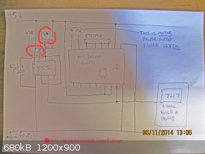
the 22 ohm resistor stops the 555 circuit from "locking up". as resistance decreases, the speed increases. 0 resistance results in the 555 freezing.
[Edited on 6-11-2014 by diddi]
|
|
|
Magpie
lab constructor
Posts: 5939
Registered: 1-11-2003
Location: USA
Member Is Offline
Mood: Chemistry: the subtle science.
|
|
I forgot to identify the IC timer:
IC timer: Texas Instruments No.: NE555DR; IC OSC SGL TIMER; $0.55
Thanks for the schematic. I guess that is +5v on the top.
As I don't have a tachometer it is difficult for me to estimate the proper speed range. But I think 60-600 rpm would be good.
[Edited on 6-11-2014 by Magpie]
[Edited on 6-11-2014 by Magpie]
The single most important condition for a successful synthesis is good mixing - Nicodem
|
|
|
Varmint
Hazard to Others
Posts: 264
Registered: 30-5-2013
Location: Near Atlanta, GA
Member Is Offline
Mood: No Mood
|
|
A stepper is a good solution when precision positioning is required, but it's loss of torque with increasing speed presents special challenges for the
driver circuitry.
Ergo, this is where the wildly divergent "motor rated voltage" and drive circuit "drive votages" come into play. A performance drive will have drive
voltages from 4 to 20X the motor "rated" voltage available, and it controls the current and drive waveforms in combination to achieve signals at the
motor terminals that do not overheat the motor, yet still have the overdrive required to counteract the motor's inductance with increasing speed.
In this application where you want perhaps a few RPM at the low end, and as much as 600 to 1000 RPM at the high end, you will reach an area whereyou
need to make the transition from micro-stepping to full stepping, and unless the driver board is specifically capable of making this crossover on it
own, you'll have to have other circuitry make this transition for you.
If you don't, your top speed will be limited by the frequency the driver can handle while micro-stepping, or, you will have to run full stepping at
all times, which is going to be subject to some harsh resonance -related vibrations that will be tough to dampen.
A better solution for this wide a range of speeds (and no genuine need for precision positioning) is a DC motor with an external (or internal if you
can find one!) optical encoder for shaft speed control.
Use a power Op-Amp to drive the motor, and on the reference input would be a pot to control the motor speed. The other input comes from a F to V
converter driven from the encoder pulses. It will present something of a balancing act to get the F to V conversion just right, but the premise is,
the amplifier will always strive to match the shaft speed (as represented by the encoder pulse frequency to voltage) to the desired speed as set by
the pot.
Some gain in the amp will help too, that way small variations in speed will result in larger variations in drive voltage/current such that the
amplifier is ready to react to variations in the load to keep the speed constant.
BTW, the F to V conversion can be done using an actual chip, or it could be accomplished with a couple of resistors and a capacitor doing a simple
integration.
The stepper could be made to work, but the speed ranges currently being discussed require a driver of significantly higher complexity than shown till
this point.
DAS
|
|
|
diddi
National Hazard
Posts: 723
Registered: 23-9-2014
Location: Victoria, Australia
Member Is Offline
Mood: Fluorescent
|
|
valid points... I have actually not invoked any microstepping features available on this driver board (which is 4-bit capable) as I felt that a
stirrer did not need to be that smooth. and the driver board is rated to 2A with heatsink (not attached, but provided in the price I paid supplier).
I have run the stepper at a few hundred hertz with success but have not finished the display circuit to check exactly (and someone "borrowed" my
frequency counter about 3 years ago)
there is certainly merit in using a DC motor and opto sensing to check revs, and would be simpler in some respects as I will need to build a divide
200 module to get rpm. although I would prolly need a division circiut anyway. I would not bother doing F/V method. I think it would be susceptible to
error under load?
anyway, hopefully the project works out OK, and it is interesting to see what can be done with junk otherwise being thrown away.
|
|
|
Varmint
Hazard to Others
Posts: 264
Registered: 30-5-2013
Location: Near Atlanta, GA
Member Is Offline
Mood: No Mood
|
|
Didi:
My objection to running full step at all times is the resonances that cause the whole system to vibrate, sometimes scarily so.
I do use a stepper for a non-precision purpose myself, the stepper drives a carboard drum I use to mix flash powder in the most uniform, safest way
possible. The driver is controlled by a ATMega328P (basically the u-controller used in an Arduino but stand alone/custom), which offers mixing modes
I refect to as "Washing Machine" and others, where the drum rotates one direction, then reverses.
The washing machine cycle is one revolution forward, half revolution back, repeat until stopped. The next mode is 2 revs forward. one rev back, and
so on. The default mode is 10 revs forward, 10 revs back, and of course can be changed at any time by recompiling.
With the drum at a 30* angle, the mixing is extremely fast in any mode, I just designed the "Washing Machine" because it's visually interesting and
shows off the capabilities of the stepper nicely. In this case, the full step resonances I've mentioned are actually advantageous, they certainly
contribute to the mixing action to some degree.
DAS
[Edited on 7-11-2014 by Varmint]
|
|
|
Magpie
lab constructor
Posts: 5939
Registered: 1-11-2003
Location: USA
Member Is Offline
Mood: Chemistry: the subtle science.
|
|
diddi: I have some resistance data from my stepper motor that may be useful. Consistent with the pin vs phase table shown on the Minebea data sheet
you linked, ie:
http://www.eminebea.com/en/product/rotary/steppingmotor/hybr...
my resistance readings are as follows:
pin 1 to pin 2: 18Ω
pin 1 to pin 3: 25Ω
pin 2 to pin 3: 18Ω
pin 4 to pin 5: 18Ω
pin 4 to pin 6: 25Ω
pin 5 to pin 6: 18Ω
All other pin combinations were of infinite resistance. Although I expected the higher readings to be double that of the lower readings I won't swear
to the accuracy of my meter either. Does this array indicate a unipolar construction? Also, why are these readings so much higher than the
resistance derived from the nameplate 1.14amps and 3.1volts, ie, R=3.1/1.14 =2.7Ω? This calculated value is consistent with those on the Minebea
data sheet also.
What is the status of this project from your end? Have you finished or are you still in the design/development stage? Even though varmint has
identified a possible weakness of the stepper motor for this application, I am still willing to procure the parts if you think it is worth a try.
Maybe just providing a higher voltage, say 24vdc instead of 12vdc, would overcome the vibration issue.
Let me know - and thanks for your work on this project.
The single most important condition for a successful synthesis is good mixing - Nicodem
|
|
|
Magpie
lab constructor
Posts: 5939
Registered: 1-11-2003
Location: USA
Member Is Offline
Mood: Chemistry: the subtle science.
|
|
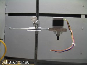
Here's a progress report on my effort to build a stepper motor stirrer. See photo below.
The stepper motor salvaged from a dead copier is mounted on a 1/2" thick slab of aluminum. This was the base of a heat sink also salvaged from one of
the dead items described in my above posts. The bolt is a 1/4" x 8" carriage bolt. The shaft attachment is a 5/16" arbor attachment from
McMaster-Carr:
http://www.mcmaster.com/#arbor-adapters/=up3sxh
The arbor attachment stud is threaded to accept a chuck, which I have been spending hours trying to find (ref 1), as it has been misplaced here at
home.
My reliable but expensive (ref 2) machinist did the machine work. I am now waiting for the electronic components to arrive. These will be used to
assemble the motor driver/controller per diddi's schematic. I will have speed control but no rpm readout. That may come later.
References:
1) "And there will come a time when fathers will not be able to find things that were on hand as recently as 6:30PM the previous day." Python,
Monty, Life of Brian
2) Cost disclosure is prohibited due to embarrassment.
The single most important condition for a successful synthesis is good mixing - Nicodem
|
|
|
Magpie
lab constructor
Posts: 5939
Registered: 1-11-2003
Location: USA
Member Is Offline
Mood: Chemistry: the subtle science.
|
|
Here's another progress report on my stepper motor stirrer project.
The motor driver electronics have been prototyped on a breadboard and tested successfully as shown in the link below. The pulse rate shown is the
lowest setting (6v) with the pot turned fully ccw. With the pot turned fully cw (12v) the pulse rate is too rapid to see, ie, the lights are just
continuously "on."
With the exception of the added LEDs and and their respective 680Ω dropping resistors, the circuit is that provided by diddi in one of the above
posts.
https://www.youtube.com/watch?v=xD-XZukfib0&feature=yout...
[Edited on 26-11-2014 by Magpie]
The single most important condition for a successful synthesis is good mixing - Nicodem
|
|
|
diddi
National Hazard
Posts: 723
Registered: 23-9-2014
Location: Victoria, Australia
Member Is Offline
Mood: Fluorescent
|
|
you will need to alter the capacitor I reckon. it can be a bit hit and miss I am afraid, and I tend to experiment with values.
I will have a look a bit later today and see what might be a good change.
|
|
|
diddi
National Hazard
Posts: 723
Registered: 23-9-2014
Location: Victoria, Australia
Member Is Offline
Mood: Fluorescent
|
|
cant access video. could you post a pic plz
|
|
|
| Pages:
1
2
3
4
..
9 |


