| Pages:
1
2 |
TheAlchemistPirate
Hazard to Others

Posts: 151
Registered: 25-3-2014
Location: The point of no return
Member Is Offline
Mood: Enigmatic
|
|
Tesla Coil Inquiry
Haven't posted here in a while...
Recently I have been learning about electronics and radio technology, and other than my whims of building a long range quadcopter that piggybacks the
cell tower network, I have been planning to build a tesla coil. I wasn't sure if this forum was the type that would have much experience with these
things (no offense), but I might as well see.
http://makezine.com/projects/make-35/six-pack-tesla-coil/
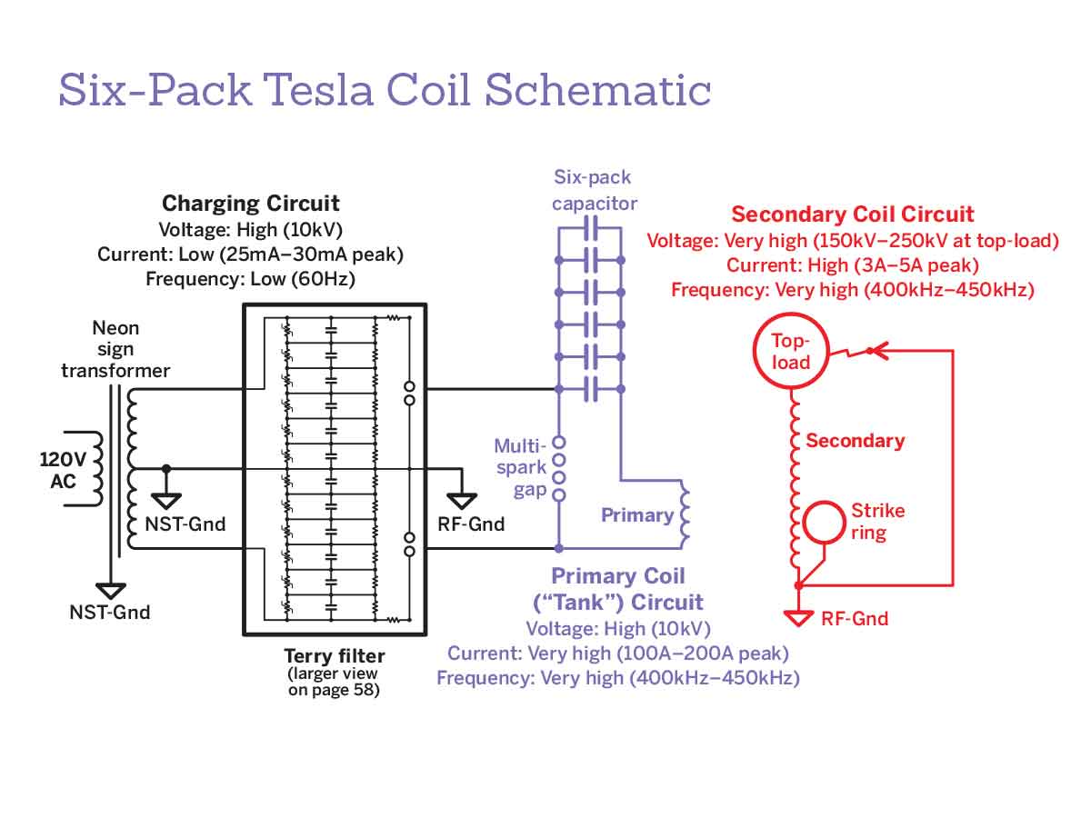
This is the tutorial I'm planning on following, and something doesn't make sense to me in this schematic from it-
https://i2.wp.com/cdn.makezine.com/uploads/2013/05/coil-sche...
The charging circuit info at the top left says it operates at 20-30 milliamps, but the primary circuit says it peaks at 100-200 amps! I figured that
the capacitors discharging would raise the current to the few amps temporarily, but that number seems insane. It makes more sense in the top right
secondary circuit info.
Another question, the recommended power source is a 10 kv Neon sign transformer, using a terry filter which I assume keeps it from exploding. It
implies that the NST only supplies 20-30 milliamps. I was wondering if I could substitute something like this.
https://www.rmcybernetics.com/shop/cyber-circuits/pulse-modu...
It claims to be able to supply 9 amps continuously, along with several hundred volts. The most intriguing feature to me is the frequency adjuster,
which can range from 0.01 hertz to 1.5 MHz! I would pair this with an ignition coil(presumably at 60 hertz) to achieve 10 kv. Could this replace an
NST?
Lastly, radios operate by transmitting rapidly pulsing electromagnetic waves, with different ways of encoding the data into the frequencies. When a
radio first receives a radio signal, it is a tiny amount of current, which can only be directly listened to with a crystal radio. This tiny amount of
current is then amplified with transistors. While it is a very small amount, radio transmitters are providing wireless energy! My question is this- If
tesla coils are among the most efficient transformers/transmitters, why aren't hobbyists tuning a large coil and a small coil to the same frequencies,
then efficiently and wirelessly transmitting power miles away?! Tesla coils were one used in radio systems, why wouldn't that still be possible?
"Is this even science anymore?!"
|
|
|
WGTR
National Hazard
Posts: 971
Registered: 29-9-2013
Location: Online
Member Is Offline
Mood: Outline
|
|
Quote: Originally posted by TheAlchemistPirate  |
Recently I have been learning about electronics and radio technology, and other than my whims of building a long range quadcopter that piggybacks the
cell tower network... |
If you ever do this, I'd like to see the details.
| Quote: | ...something doesn't make sense to me in this schematic from it- https://i2.wp.com/cdn.makezine.com/uploads/2013/05/coil-sche...
The charging circuit info at the top left says it operates at 20-30 milliamps, but the primary circuit says it peaks at 100-200 amps! I figured that
the capacitors discharging would raise the current to the few amps temporarily, but that number seems insane. It makes more sense in the top right
secondary circuit info. |
This can be shown using complex algebra.
In any parallel resonant circuit that uses high "Q" inductors and capacitors, the circulating currents can be extremely high, even when the source
driving it only supplies low currents.
The capacitive and inductive currents can be represented by imaginary numbers, and it just so happens that a tuned circuit at resonance has capacitive
and inductive reactances that are both equal and opposite. The reactive currents cancel out, even though they may be extremely high inside the tuned
circuit. In a parallel tuned circuit, the only energy that needs to be supplied is equal to the resistive losses (which are hopefully minimal).
In this particular circuit, the primary circuit is series tuned, and is being driven by a 60Hz signal. The impedance of the "six pack capacitor" at
this frequency is extremely high (≈R - 500,000j), hence the currents are very low (≈R + 0.020j) during charging. When the spark gap fires, the
tuned circuit oscillates for a short period of time at its natural frequency, which is much higher, around 400-450kHz. At this point the peak
currents within the tuned circuit can rise very high for a brief period of time, apparently 100-200A from the schematic. This approximately checks
out, since the impedance of the capacitor is ≈ R - 70j. The power supply would not see anything near this level of current coming out of it,
provided that it is protected with a filter.
The "terry filter" shown in the schematic has wires going to nowhere. I'd suggest looking for a better schematic.
This is a very glossed-over explanation, but hopefully it explains things a little.
|
|
|
aga
Forum Drunkard
Posts: 7030
Registered: 25-3-2014
Member Is Offline
|
|
Probably means using a SIM card using 3G to get the data connection.
4G would not be much use outside a city.
[Edited on 30-8-2015 by aga]
|
|
|
TheAlchemistPirate
Hazard to Others
Posts: 151
Registered: 25-3-2014
Location: The point of no return
Member Is Offline
Mood: Enigmatic
|
|
...
I had written a massive wall of text detailing how my cell tower-comandeering quadcopter would work, only to click "BB Code" to get some freaking
italics and delete the whole thing.
Perhaps sometime in the future I will acquire a great wealth of motivation and rewrite the whole novel, on the offchance someone may actually
understand it. My head hurts now and I haven't slept in days...
Pretend you have just memorized 57 electronics data sheets, and now have a rather severe aneurism from it. Maybe channel your memories of being in
an electrical engineering class, after you had stayed up all night putting a university patrol car atop the massive dome building on the campus. I
don't know.
Back to the tesla coil- I think I know what you mean now. So for a very brief moment an extremely efficient connection is formed in the tank circuit
and hundreds of amps can flow freely through the spark gap into the primary, only for the power to immediately plummet to near 0. If you could measure
the spark gap amperage with an ocilloscope wouldn't it be very jagged lines that are like extremely thin recatngles? I had more things to say, but I
seem to have lost all of my higher-level mental abilities after that incident.
EDIT: I have no idea what's going on with these columns, maybe they're trying to hold up my wall of text at the top. I'm too tired to care.
[Edited on 30-8-2015 by TheAlchemistPirate]
"Is this even science anymore?!"
|
|
|
IrC
International Hazard
Posts: 2710
Registered: 7-3-2005
Location: Eureka
Member Is Offline
Mood: Discovering
|
|
| Quote: Originally posted by WGTR | | The "terry filter" shown in the schematic has wires going to nowhere. I'd suggest looking for a better schematic. |
If you carefully read the article you will see a link to the corrected schematic.
To the OP: Why bother with this design, throwing darts at a wall of numbers would end up giving better design values. I suggest you search the web
and find a better secondary design. The diameter is too small and there are far too many turns of too fine a wire. The secondary self capacitance
would load it so hard there will be nothing near the resonant rise one could achieve with a heavier gauge wire, taller coil form, and increased
diameter. Not to mention the top load is too large with too great a self capacitance for the power level of this coil meaning far longer sparks could
result if one were to compromise here by not trying to store so much energy in such a heavily damped low power design.
I did not see where they mentioned the Cl2 that will be bubbling out of the capacitors. Not to mention the tendency of that type glass to crack if one
were ever to get a decent circulating current in the primary. Just find the correct value and order a proper capacitor with at least a 30 KV rating.
The 1K resistors are going to severely limit charging current, by far too much. An experienced coil builder could write a book on all the reasons that
design sucks. There are many sites with far better information and plans. One fairly decent site is linked in the article if you read it carefully.
The corrected schematic will show you the proper filter circuit and it does have some features worth considering although I would make several
changes.
"Science is the belief in the ignorance of the experts" Richard Feynman
|
|
|
IrC
International Hazard
Posts: 2710
Registered: 7-3-2005
Location: Eureka
Member Is Offline
Mood: Discovering
|
|
How did my reply end up long thin and joined to aga's post?
"Science is the belief in the ignorance of the experts" Richard Feynman
|
|
|
aga
Forum Drunkard
Posts: 7030
Registered: 25-3-2014
Member Is Offline
|
|
Sorry. That was me missing a bracket in my last post.
|
|
|
TheAlchemistPirate
Hazard to Others
Posts: 151
Registered: 25-3-2014
Location: The point of no return
Member Is Offline
Mood: Enigmatic
|
|
After reading through the instructions again, I saw the answer to one of my questions. When talking about the power supply, it states "solid state
voltage converters are not suitable for this application". So I would have to use a transformer instead of a dc power supply like the one I mentioned
above? What is the difference between them if they both provide 25 mA at 10000v and 60hz?
I'll take your word for it and find another tutorial. I just want to begin with a simple(though not necessarily small) design. Also, I cannot for the
life of me find GF protection-free NSTs anywhere. About the "six pack" capacitor bank(which are essentially Leyden jars), I don't think that the idea
of using them is dumb as a whole. I also wondered about the potential of the jars to electrolyse the salt into sodium and chlorine, but figured it
wouldn't happen if there wasn't much leakage. Would sodium bicarbonate work to lower the resistance of water? I really don't want to deal with trying
to line the inside of a container with foil, or spending lots of $$$$ on fancy capacitors. I doubted the suitability of as an insulator too, after
reading a very technical page about it liking to absorb current between the plates.
I'm rather awful at understanding these mathematical/algebraic equations people seem to pull out of thin air(not implying they're false), so I was
wanting to start with something simple and possibly substitute parts with javaTC. While I haven't bought anything yet, I would also prefer the design
to be use the variable power supply, if possible. How about this tutorial? http://www.instructables.com/id/How-to-build-a-Tesla-Coil/?A...
"Is this even science anymore?!"
|
|
|
TheAlchemistPirate
Hazard to Others
Posts: 151
Registered: 25-3-2014
Location: The point of no return
Member Is Offline
Mood: Enigmatic
|
|
After reading through the instructions again, I saw the answer to one of my questions. When talking about the power supply, it states "solid state
voltage converters are not suitable for this application". So I would have to use a transformer instead of a dc power supply like the one I mentioned
above? What is the difference between them if they both provide 25 mA at 10000v and 60hz?
I'll take your word for it and find another tutorial. I just want to begin with a simple(though not necessarily small) design. Also, I cannot for the
life of me find GF protection-free NSTs anywhere. About the "six pack" capacitor bank(which are essentially Leyden jars), I don't think that the idea
of using them is dumb as a whole. I also wondered about the potential of the jars to electrolyse the salt into sodium and chlorine, but figured it
wouldn't happen if there wasn't much leakage. Would sodium bicarbonate work to lower the resistance of water? I really don't want to deal with trying
to line the inside of a container with foil, or spending lots of $$$$ on fancy capacitors. I doubted the suitability of as an insulator too, after
reading a very technical page about it liking to absorb current between the plates.
I'm rather awful at understanding these mathematical/algebraic equations people seem to pull out of thin air(not implying they're false), so I was
wanting to start with something simple and possibly substitute parts with javaTC. While I haven't bought anything yet, I would also prefer the design
to be use the variable power supply, if possible. How about this tutorial? http://www.instructables.com/id/How-to-build-a-Tesla-Coil/?A...
EDIT: for some reason the post copied itself
[Edited on 30-8-2015 by TheAlchemistPirate]
"Is this even science anymore?!"
|
|
|
IrC
International Hazard
Posts: 2710
Registered: 7-3-2005
Location: Eureka
Member Is Offline
Mood: Discovering
|
|
What is the difference between them if they both provide 25 mA at 10000v and 60hz?
Maybe one of them is not all that concerned with spikes blowing semiconductors. Go to google type in tesla coil and start reading. There are so many
good sites out there you will have no problem finding a design which is within your reach and hopefully not excessively life threatening. NST's are
great after you are familiar with the safety aspects. Start with some smaller design that operates on say 12 volts, like a 555/power mosfet driving an
old car ignition coil as your high voltage source to drive the primary circuit of a small coil design. After you have the learning experience of
getting the crap shocked out of you a few times in a fairly non lethal setup you will have a more refined sense of caution when you graduate to
dangerous designs. Maybe with these smaller designs even your liquid/glass capacitor is a reasonable approach in the interest of staying low budget.
Eventually you will need to find and invest in some decent capacitors but until you know the parameters needed there is no point in worrying about
that yet. Also study stun gun circuits of the spark gap type as this is actually not a bad source of primary power in a small coil.
Just keep in mind with little knowledge in high voltage and electronics it isn't all that wise to begin your studies by playing with lethal voltages
and currents.
"Science is the belief in the ignorance of the experts" Richard Feynman
|
|
|
TheAlchemistPirate
Hazard to Others
Posts: 151
Registered: 25-3-2014
Location: The point of no return
Member Is Offline
Mood: Enigmatic
|
|
I still don't understand why power pulse modulators can't be used in place of normal transformers, is it because the negative terminal receives huge
voltages that it wasn't designed for? I am now looking into solid state coils since they use lower currents and don't require hard to find
transformers. They all have massive circuit schematics however. I'm not looking to produce 2 foot arcs right now, I just want to actually understand
how the circuit works and why each component is used. There are so many terms on java TC and such that I have never heard of. I am currently doing all
the projects in the book Make:electronics but only understand basic electrical math and terms. The projects are on hold for now however since I
accidentally fried all my 2n2222 transistors. The most important thing to me is to understand exactly why everything works, then I can begin my plans
to rule the world.
The stun gun circuit looks interesting, and seems similar to some solid state schematics I have seen. Something that feels surreal to me in
electronics is seeing all these same components over and over again, like the 555 chip, 14007 diode, 2n2222 transistor, it creates the illusion that I
know what I'm doing  . I wonder how long the stun gun circuit can run, maybe a
long time if it is ventilated... So, if a blundering sixteen year old were to replace a stun gun button with a switch, replace the leads with a
primary winding, and throw a wire-wrapped pvc pipe with a toroid on top(from a failed sstc kit from christmas-soldering sucks long story short), into
the middle of it, how would it go down? What if that sixteen year old managed to calculate the general size of the required primary and secondary
coils? . I wonder how long the stun gun circuit can run, maybe a
long time if it is ventilated... So, if a blundering sixteen year old were to replace a stun gun button with a switch, replace the leads with a
primary winding, and throw a wire-wrapped pvc pipe with a toroid on top(from a failed sstc kit from christmas-soldering sucks long story short), into
the middle of it, how would it go down? What if that sixteen year old managed to calculate the general size of the required primary and secondary
coils?
EDIT: I saw a project on instructables where a kid threw together a 12v power source, which went to a makeshift 555 timer which powered the leyden jar
and spark gap. He indiscriminately wound a primary and secondary, and attached some sort of metal ball to the top. At first, the high voltage current
went to the negative terminal of the timer circuit and blew up the 555 of course. But, to fix that, he attached a photocoupler! This kept the high
voltages from affecting the rest of the circuit and still provided a ground for it. What if I used a photocoupler on the negative terminal of the
power pulse modulator? Then I could drive a circuit that would normally require an NST with an accurate and multi-use power supply.
[Edited on 30-8-2015 by TheAlchemistPirate]
"Is this even science anymore?!"
|
|
|
aga
Forum Drunkard
Posts: 7030
Registered: 25-3-2014
Member Is Offline
|
|
What is it that you would like to actually Do TheAlchemistPirate ?
Most of this thread is really confusing, so just lay it out flat, please.
|
|
|
TheAlchemistPirate
Hazard to Others
Posts: 151
Registered: 25-3-2014
Location: The point of no return
Member Is Offline
Mood: Enigmatic
|
|
To be honest, I have simply been writing what I was thinking about, and my mind is pretty chaotic sometimes. I just want to build a tesla coil, and
understand it. Maybe this would be more suitable on an electronics forum. That's about it.
"Is this even science anymore?!"
|
|
|
aga
Forum Drunkard
Posts: 7030
Registered: 25-3-2014
Member Is Offline
|
|
You need to drink more.
Anyway, the Tesla thing is quite simple : you got 230 0r 110 V AC coming in.
Either recitfy it or just chop it up raw.
Feed it into a big-ass coil of copper pipe after it is chopped up.
This is called the Primary coil.
The Secondary coil is usually wound on a PVC pipe using much finer enamelled copper wire, around 32swg size, and LOTS of turns.
What is happening is that the electrical energy is being fed into the Primary coil, creating an Electromagnetic field.
The Secondary coil of wire picks this energy up and amplifies the Voltage (consequently reducing the available Current, as the Energy remains
constant).
It does that by having a lot more turns of copper than the Peimary coil has.
2N2222 is ancient. Look for HEXFETS instead (if using DC) or Triacs if chopping up AC.
http://www.teslacoildesign.com/
|
|
|
WGTR
National Hazard
Posts: 971
Registered: 29-9-2013
Location: Online
Member Is Offline
Mood: Outline
|
|
I'm not sure what you're referring to with the photocoupler. I'd have to see a schematic of it. IrC has the right idea, of course, about starting
small. I second the idea of using an automotive ignition coil (the round cylindrical ones). Those are available at any auto parts store and salvage
yard. They normally have a 1:100 voltage step up ratio, and are made to switch up to 1kHz or so. Don't plug this directly into the wall. It needs a
MOSFET to switch it in a flyback converter configuration. I'm using an MSD 8202 in a flyback converter, and it works well. I've gotten up to about
30,000V from of it without much trouble.
As an aside, high voltage sparks can do funny things to circuits. When high voltage breaks down an air gap, it can do so very rapidly, delivering
nanosecond pulses to whatever it hits. If the air gap is discharging a capacitor, it's possible to deliver 1,000's of amps in that brief period of
time. If the spark hits a ground plane, it's possible for the ground to "bounce" briefly, destroying nearby components. That may be why they are
saying not to use solid state converters. If care is taken, though, it should be possible.
|
|
|
TheAlchemistPirate
Hazard to Others
Posts: 151
Registered: 25-3-2014
Location: The point of no return
Member Is Offline
Mood: Enigmatic
|
|
It was a rather shoddily built design that used the photocoupler, I'm just going to forget about that for now. I feel extremely overwhelmed right now
with all of these solid state designs, so I'm welcome to anything that I don't need an electrical engineering degree to understand. I have read many a
legend of these magical ignition coils that are the key to all that is high voltage and dangerous. This may sound dumb but is a flyback converter
similar to a flyback transformer? I considered using one of those with a solid state power supply but I have no idea how it works...
I would simply use a transformer and make a "normal" coil if I could find one under 60$(including shipping). By what do you mean "care should be
taken"? Do you mean I should isolate the spark gap from the solid state power supply? I don't think I would be able to solder any of these 40+
component circuits but I also can't afford to spend 100$ on a part I can only use for one device.
What I tried to say in one of my above posts is that I got a simple sstc kit for christmas, and spent 5 months just trying to get the secondary
wound. I then started working on soldering only to totally screw it up, only to use my spare parts to try again, and screw it up again. And it only
had 8 components! I still have the 4" sphere toroid however.
"Is this even science anymore?!"
|
|
|
IrC
International Hazard
Posts: 2710
Registered: 7-3-2005
Location: Eureka
Member Is Offline
Mood: Discovering
|
|
"I don't think I would be able to solder any of these 40+ component circuits"
Hopefully the day will come you realize you only learn by doing when it comes to any mechanical skill which is inherently an art. Study Marx banks
maybe that will be simpler if playing with sparks is what you want to do. Or better yet build a Van De Graaff not much soldering involved there
(battery holder to switch to motor).
"Science is the belief in the ignorance of the experts" Richard Feynman
|
|
|
TheAlchemistPirate
Hazard to Others
Posts: 151
Registered: 25-3-2014
Location: The point of no return
Member Is Offline
Mood: Enigmatic
|
|
Don't think that I am not reading about any of these things you guys refer to. I only say "I don't understand this at all" because the way they seem
to glance past something like what causes a flyback transformer to work is very frustrating to me. I have soldered simple circuits with 10 components
on perfboard before, and am slowly improving. I actually threw together a Van De Graaf generator before. It worked for about five minutes and made
half inch sparks until something shifted and it didn't generate any more sparks after that.
If you think I could build one of these circuits I may try, but I will only understand the general function of the circuit instead of why each
component is there, which isn't what I wanted.
I will look into the Marx banks though.
"Is this even science anymore?!"
|
|
|
IrC
International Hazard
Posts: 2710
Registered: 7-3-2005
Location: Eureka
Member Is Offline
Mood: Discovering
|
|
"It worked for about five minutes and made half inch sparks until something shifted and it didn't generate any more sparks after that."
Then you went on to something else, soldered your kit, tried to wind a coil, and stopped yet again. Now you are out asking people questions in an
effort to move on to something else. This is a problem. One if you fail to conquer it is unlikely you can ever advance. Why did you not experiment to
see why the Van De Graaff failed, and get it working again. The effort would help you learn. Why did you not rewind your coil, re-solder the board in
the kit with new parts? If you wrecked the foil build it on a perfboard. IIRC you said 8 parts, how hard can this be. Likely not very expensive
either. This I think is your real problem, always half trying, giving up and moving on. Fix it. Along the line you will learn perseverance, patience,
and likely how it is things work.
This is how I and likely virtually all the members here learned. Yet do so starting only with fairly safe projects. I have seen many who were far too
young and lacking in experience with this drive to take on the dangerous projects first. In the interests of full disclosure I must say I also began
this way and if I think back a half century many NDE's come to mind. All of which I survived but many only barely. Since the advent of the internet I
have read the stories of many who did not. Involve a parent and/or teacher in your projects, this will help you learn while providing a margin of
safety. Also if you have trouble winding a secondary you may luck out by talking one of them into doing it for you. This is how a kid got 1st place in
a science fair I visited in 1969, he built all but the coil getting his dad to do that after several failures on his own. Something to consider at
least.
Edit to consider this: "because the way they seem to glance past something like what causes a flyback transformer to work is very frustrating to me"
You, me, and all who study. In virtually everything. Something you will always deal with. Sometimes the writer assumes others know more than they do
so they gloss over important points. Sometimes it is being lazy and more often than one may realize they just do not know themselves. You will always
deal with this and getting good at searching, spending time in study, asking for clarification from others (as little as possible don't ask for spoon
feeding in lieu of effort on your part), are a few ways to overcome this obstacle.
[Edited on 8-31-2015 by IrC]
"Science is the belief in the ignorance of the experts" Richard Feynman
|
|
|
aga
Forum Drunkard
Posts: 7030
Registered: 25-3-2014
Member Is Offline
|
|
If you're new to electronics, then a useful way to learn the basic soldering skills is to go and buy some small copper pins/nails.
Knock these into a plank of wood and practice soldering wires to them to connect them up.
No components get broken if you screw it up, and it's easy to see a 'good' soldered joint when you make one.
Once mastered (an hour ?) you can then draw a circuit on the plank of wood, hammer copper nails in at the connection points, then solder your
components to the nails.
All very easy and much clearer as you can see the actual circuit.
like this : http://www.stormwise.com/vlf.htm
|
|
|
WGTR
National Hazard
Posts: 971
Registered: 29-9-2013
Location: Online
Member Is Offline
Mood: Outline
|
|
| Quote: Originally posted by IrC |
Edit to consider this: "because the way they seem to glance past something like what causes a flyback transformer to work is very frustrating to me"
You, me, and all who study. In virtually everything. Something you will always deal with. Sometimes the writer assumes others know more than they do
so they gloss over important points. Sometimes it is being lazy and more often than one may realize they just do not know themselves. You will always
deal with this and getting good at searching, spending time in study, asking for clarification from others (as little as possible don't ask for spoon
feeding in lieu of effort on your part), are a few ways to overcome this obstacle.[Edited on 8-31-2015 by IrC] |
Yes. This. I've been immersed in electronics for 25 years. These assumptions about others' knowledge are almost unavoidable.
Part of the self-study process is learning how to piece together information from different sources. It is rare that one source/author presents an
entire topic in a sufficient way. You pick up nuggets of useful information from multiple sources, and piece them together, learning how to filter
out the chaff. It's not easy, but eventually you learn how to recognize good information quickly, and not waste time on the fluff.
I try to write things that generate leading questions, if one chooses to ask them. I don't really have time to explain an entire topic start to
finish, because that means I have less time in the lab. I'm a very slow writer. However, I'm happy to answer questions.
A flyback converter contains a flyback transformer. If you look at a schematic of a points-based automotive ignition system, you are essentially
looking at a flyback converter that uses a mechanical switch (points) instead of a MOSFET. You can even replace this switch with a mechanical vibrator, if you can find (or build) one. Personally, I do things the solid-state way.
When you build things for the first time, it is helpful (and normal) to test things in sub assemblies. When I build a coil, I test it with a meter to
verify its inductance, that it doesn't have turns shorted, etc. I'll check the MOSFETS to make sure that they're switching, that they have proper
gate drive, etc. Then perhaps I'll wire up all the inductors and MOSFETs, and bring up the supply voltage slowly, looking for possible over-voltage
problems, or current fault conditions. For a high voltage supply, then I'll characterize its output, see how it handles short-circuit conditions,
etc.
Explaining something so that someone else can build it is actually very difficult. The one doing the explaining has to consider a wide variety of
skill levels in the audience, every possible thing that can go wrong in assembly. Something that one person already knows how to do, and does without
thinking about it, can take an hour or two to explain to someone else. For similar reasons, kits can be good ones or poor ones, depending on how much
care the person designing the kit put into it. A poor one may take considerable debugging to get it to work for the first time.
Some people, like Tesla, can visualize entire projects in their heads, do some calculations, and then build something that works the first time. Most
of us, however, need to spend time in the lab getting our hands dirty. Don't be afraid to blow up components, if it helps you learn. Small signal
transistors are cheap. I usually buy them in 100 piece quantities. Things like resistors and capacitors are easy to reuse, if you stay within their
voltage and power limits.
[Edited on 8-31-2015 by WGTR]
|
|
|
aga
Forum Drunkard
Posts: 7030
Registered: 25-3-2014
Member Is Offline
|
|
That's a very good point, also the one about buying in quantities of 10 (at least).
Too often a lot of time is wasted doing careful calculations when the detonation of $0.05 component would give you exactly the figure you were looking
for.
If explosion is likely to happen, wear your lab goggles, as bits can fly around.
https://www.youtube.com/watch?v=3b7mjukhTyQ
|
|
|
WGTR
National Hazard
Posts: 971
Registered: 29-9-2013
Location: Online
Member Is Offline
Mood: Outline
|
|
Might I also suggest, that if you want to learn how transistor circuits work, then 2N3904's (NPN) and 2N3906's (PNP) are good generic choices for low
power/voltage experimenting. They are usually cheaper than 2N2222's. A quick check on eBay showed 100 x 2N3904 pieces available from Tennessee for $4, with free shipping, for example.
When I started out I did small assemblies on wood, like aga suggests. If you have heavy solid copper wire, drilling small holes in
the wood and hammering pieces of the wire tightly into the board to make mounting posts works as well. I built several radios on stiff cardboard.
The connections were made by wrapping copper wire around the leads and then soldering.
|
|
|
aga
Forum Drunkard
Posts: 7030
Registered: 25-3-2014
Member Is Offline
|
|
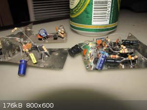
I made some radio circuits on flattened out beer cans to get a great earth plane, and also screen the circuit when finished simply by folding the
metal into a box shape and tack-soldering the edges together.
The surprise was that the solder flowed into the can material, which i assumed was Steel as it is magnetic.
Whatever it is, it takes solder really well, and it certainly isn't just Tin.
Edit:
Found some of those circuits in the junk box.
Here's some radio stuff on beer-tin ground plane with the donor material in the background :
[Edited on 31-8-2015 by aga]
|
|
|
WGTR
National Hazard
Posts: 971
Registered: 29-9-2013
Location: Online
Member Is Offline
Mood: Outline
|
|
Why am I not surprised that this project of yours involved beer in some way? 
I've cut up metal food cans and found them to be solderable as well. They seemed to work OK for shielding purposes.
|
|
|
| Pages:
1
2 |


